Conceptual Design of a High-Speed Variable Configuration Compound Helicopter Fabio Riccardi† Postdoctoral Research Fellow †
Radek Possamai† Ph.D. Candidate
Dipartimento di Scienze e Tecnologie Aerospaziali - Politecnico di Milano Via La Masa 34, 20156 Milano, Italy ABSTRACT 31th
In response to the AHS Student Design Competition Request for Proposal, one of the Politecnico di Milano entrants teams in graduate category submitted the co-X HERMES project. The RFP, titled X-VTOL, was inspired to DARPA 2013 program called VTOL X-PLANE, soliciting proposal on the design of a VTOL experimental aircraft capable to increase top speed without sacrificing range, payload and the ability to operate in hover. The co-X HERMES is a fully compounded manned helicopter with coaxial rotor and pushing propeller unit mounted in tail, adopting dedicated design features in order to go beyond the limitations of this architecture and fulfill the RFP requirements. The aircraft works without thrust compounding from hover to about 140 kt, then the transition maneuver is performed and vehicle switch from helicopter to airplane modality to attain higher speed. The change of configuration involves: the main wing span, the rotors diameter and their angular velocity. In this paper the vehicle conceptual design process will be described, providing details about the most critical systems: variable rotor diameter, variable wing span and transmission. The performance evaluation will be presented, demonstrating the RFP requirements fulfillment, together with the results of conducted rotor multibody analysis and vehicle static stability analysis. Moreover preliminary considerations about the transition maneuver, the flight control system and the emergency operations will be discussed.
INTRODUCTION
Tilt-rotor represents a viable performance compromise between an helicopter and a turboprop aircraft: Bell-Boeing V22 and Agusta-Westland AW609 demonstrate it. The main drawback of this configuration is the lower rotors efficiency in hover respect to an helicopter of the same gross-weight: to ensure a good propulsive efficiency in airplane mode rotors must be smaller (with higher disk loading) and blades must have a very high twist in order to work like a propeller. These opposite needs lead to numerous aerodynamic design trade-offs, as discussed in (Ref. 2). In addition when in hovering the wings operate in rotor downwash, which produces large download (especially for tilt-rotor, less for tilt-wing): various techniques are used to minimize it, as discussed in (Ref. 3). The wing also influences rotor performance degrading the figure of merit, see (Ref. 4). A variable diameter rotor can be considered to optimize the efficiency in both flight modality, as proposed and successfully tested in wind tunnel, see (Ref. 5). Clearly the tilting system involves an increment in vehicle complexity and then an increase in empty weight. Regarding the compound solution, in the 1960s several compound experimental vehicle successfully flown, only thrust compounded or fully compounded (with also lift augmentation through lifting wings), adopting various solution for the auxiliary propulsion device. We can cite for example the Piasecki Pathfinder and the Sikorsky XH-59A. On the last one was tested the Advancing Blade Concept (ABC), a rigid coaxial rotor system designed to alleviate the retreating blade stall by allowing a more symmetric distribution of lateral airloads
The challenging X-VTOL Request For Proposal (RFP) requirements, far beyond the capability of conventional rotorcraft architecture, are recalled below: • REQ.1: sustained high speed flight at true airspeed between 300 kt and 400 kt; • REQ.2: aircraft hover efficiency within 25% of the ideal power loading (at sea-level standard conditions); • REQ.3: aircraft cruise lift-to-drag no less than 10; • REQ.4: useful load fraction no less than 40% gross weight with a payload fraction no less than 12.5% gross weight. The submitted design shall be representative of a manned or unmanned flight demonstrator aircraft with a maximum gross weight between 10000 lb and 12000 lb. The need to overcome the speed limitation of conventional helicopter is not new for rotorcraft community and several studies, concepts and flying prototypes for high speed rotorcraft designs were developed, as summarized in (Ref. 1) Chapter 6.11 and the references therein. Despite the research effort, there is no high speed rotorcraft currently flying, with a proven capability and relatively mature technology, except the following two main categories: tilt-rotor and compound helicopter. The vehicle configuration selection was focused mainly on these two possibilities. Presented at the AHS 71st Annual Forum, Virginia Beach, c 2015 by the American Virginia, May 5–7, 2015. Copyright Helicopter Society International, Inc. All rights reserved. 1
• Variable rotor diameter: rotors blades are fully extended in helicopter mode maximizing the hover efficiency and retracted after the transition to airplane mode in order to avoid compressibility effect on advancing rotor region until maximum speed; • Slowed rotor: together with diameter reduction the rotors are slowed after transition to airplane mode for the same reason above, see (Ref. 9); • Extended hub fairing: coaxial system hub is faired in order to reduce its parasitic drag; moreover the fairing covers the inner portion of rotor avoiding blade stall of retracting region at high speed, reducing rotor drag in airplane mode.
over the rotor disc, see details in (Ref. 6) and (Ref. 7). The interest on this type of rotorcraft is recently reemerged as evidenced by the development of two demonstrators: Sikorsky X-2 and Eurocopter X3 . Both have achieved maximum level speed of about 250 kt, relatively close to the typical tilt-rotor performance, around 275 kt. In order to avoid compressibility effects on the advancing blade arising at such flight speed, both vehicles adopt a slowed rotor solution: a maximum RPM reduction of 20 − 30% seems possible before aeroelastic issues due to flapping rigidity loss become critical, see (Ref. 8) and (Ref. 9). As pointed out for tilt-rotor, also compound suffers the same major drawbacks: increase in empty weight cause mechanical complexity, download penalties in hovering due to lifting surface placed in rotor downwash.
The co-X HERMES works in fully compounded configuration only during the transition maneuver. When operates in airplane mode the coaxial system is offloaded but kept in rotation and controlled by AFCS for a dual purpose. First, maintain the rotor tip-path-plane angle of attack null whatever are the vehicle pitch and roll attitude angles, limiting the rotor drag. Secondly, have an auxiliary attitude control device, aiding aerodynamic control surfaces (flaperons, all-moving canard stabilators, rudders), with an improvement in vehicle maneuverability. The aircraft can be configured for executing 3 mission profiles, for which VTOL and hovering capability can be essential as well as high speed and range: Search and Rescue, Air Medical Services and Air Transport Services.
VEHICLE CONFIGURATION SELECTION AND MAIN DESIGN FEATURES In light of above section considerations does not emerge some strong pro and con to prefer tilt-rotor or compound solution to fulfill the RFP requirements, both are viable but improvement respect to classical configurations are needed. For a comprehensive performance comparison of preliminary designed tilt-rotor and compound helicopter for assigned mission see (Ref. 10) and (Ref. 11). Conventional tilt-rotor use a unique source of thrust with an inherently compromise in rotor performance for the two operating modality. On the contrary compound helicopter can use two separate sources: the idea is to exploit this separation in order to optimize the performances in both hover and high speed flight, see (Ref. 12). Therefore the choice of the student team developing the coX HERMES fell on fully compounded manned helicopter, adopting dedicated design features in order to go beyond the limitations of this architecture and fulfill the RFP requirements. The aircraft works without thrust compounding from hover to about 140 kt, then the transition maneuver is performed and vehicle changes configuration to airplane modality to attain higher speed. The following list summarizes the main design choices made and relative motivations:
VEHICLE SIZING Due to the double operating modality (helicopter and airplane) and its non conventional architecture it was necessary to adopt an hybrid approach to the vehicle sizing problem, combining properly both the methods in literature for fixed wing and rotary wing aircraft design. In this section will be described the adopted approaches and obtained results in preliminary sizing of the coaxial rotor and the wing surface. Moreover the vehicle drag and vertical drag estimation will be discussed. In the whole sizing procedure the MTOW of co-X HERMES was imposed to be 12000 lb, upper bound defined in RFP. Coaxial rotor sizing
• Coaxial rotor: net size of the rotors is reduced (for a given helicopter gross weight), no tail rotor is required for anti-torque purposes, more symmetric distribution of airloads over the disc and potential capability to reach high advance ratio, (Ref. 7); unique source of lift and propulsion in helicopter mode and offloaded after transition in airplane mode; • Pusher propeller: single ducted unit mounted in tail, activated for transition and unique source of propulsion in airplane mode; • Canard configuration and variable main wing span: the main wing, together with the forward wing, forms a canard configuration in airplane mode to maximize cruise efficiency, and its the unique source of lift. In helicopter mode the main wing is retracted in order to reduce the surface located in rotor downwash and reduce the vehicle moment of inertia for better maneuverability;
Regarding the helicopter mode, the first system to size is the coaxial rotor, setting its fundamental parameters: radius, number of blades, blade chord (hence rotor solidity) and angular velocity. Rotor preliminary sizing was targeted to fulfill the REQ.2 of RFP regarding hovering efficiency. The coaxial system has been optimized for hovering condition because it is not requested to reach particularly high speed in helicopter mode. The hover efficiency is defined in (Ref. 13) Chapter 5, by the ratio between the ideal and the real power loading, and applying the proper modification in order to taking into account the induced power losses caused by wakes interaction characterizing coaxial architecture, as discussed in (Ref. 14), it results: CT 3/2 σCd0 i−1 CT h coax κκint √ + (1) PLReal = ΩR 8 2 2
coax PLIdeal =
CT 3/2 i−1 CT h κκint √ ΩR 2
(2)
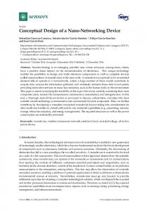
where CT is the rotor thrust coefficient, Ω is the rotor angular velocity, R is the rotor radius, σ is the rotor solidity, Cd0 is the blade section zero-lift drag coefficient assumed equal to 0.011 (NACA 0012 airfoil), κ is the induced power factor with the typical value of 1.15 and κint is the interference-induced power factor for coaxial rotor. As reported in (Ref. 14), assuming the case of balanced torque with the lower rotor operating in the fully developed slipstream of the upper rotor, κint is equal to 1.281 from momentum theory approach, a value close to one deduced from experiments but overestimated (guarantying precautionary calculation). The solidity definition was modified in order to exclude the area of extended hub fairing in the computation because non effective in terms of momentum theory considerations: referring to Figure 1 the standard form implies an overestimate, while the alternative solution marked as 2 underestimates solidity because it considers a circular rotor disk area instead of a more realistic annular section. Solution marked as 1 seems to be the best one and was adopted.
Fig. 2: CT /σ bound imposed by power loading ratio requirement. • define upper and lower bounds on CT /σ (as explained above); • adopt the alternative definition of solidity seen before; • calculate rotor radius required to fulfill imposed bounds; • check Mach limit to avoid compressibility effects (assumed equal to 0.83) at advancing blade tip for intended maximum forward flight speed (and altitude) in helicopter mode (maximum rotor angular velocity and radius) and airplane mode (minimum rotor angular velocity and radius). The iterative process implemented for rotor radius and angular velocity sizing is summarized in Figure 3.
Fig. 1: Rotor solidity alternative definitions. The power loading (PL) is the most important parameter to evaluate rotor efficiency and it is primarily influenced by disk loading (DL). It means that high PL gives high efficiency value but low DL with higher rotor radius as a consequence. The REQ.2 of RFP states that the real power loading must be within the 25% of the ideal one, hence a power loading ratio coax /PLcoax greater than 1.333. Exploiting the Equations 1 PLIdeal Real and 2 the power loading ratio as a function of rotor blade load coefficient CT /σ is represented in Figure 2: the bound on power loading ratio impose a CT /σ greater than 0.08, adopting a precautionary margin of 10% respect to REQ.2 limit. As stated in (Ref. 13) Chapter 5 the upper limit of CT /σ is about 0.16: above blades stall occurs. It bounds also the maximum rotor Figure of Merit (FM) achievable: for a coaxial architecture is about 0.65. The procedure adopted to obtain a preliminary sizing of the coaxial rotor, guaranteeing the above requirement, is the following:
Fig. 3: Rotor radius and angular velocity sizing process. The considered sizing flight conditions in terms of compressibility effects on advancing rotor region are:
• define ideal and real PL curves for coaxial rotor as function of CT /σ ; • impose the PL bound defined by REQ.2;
• helicopter mode: airspeed of 155 kt at about 9800 ft; 3
• airplane mode: airspeed of 388 kt at about 16400 ft.
configuration has been chosen to guarantee stability and symmetry for a balanced behavior: this is required for the considered homokinetic rotor articulation (see dedicated rotor design section). As a result the blade chord was set equal to 1.1 ft.
In Figure 4 are showed the results of conducted trade-off analysis in order to select the proper mixing between rotor radius reduction and angular velocity slowdown for airplane mode operations, once imposed the Mach number limit at advancing blade tip as defined previously. In Table 1 and Table 2 are reported the rotor sizing bound values in terms of radius and angular velocity, relative to blade load coefficient CT /σ upper and lower limits, at maximum airspeed and altitude condition respectively in helicopter mode and airplane mode.
Wing area sizing and vehicle drag estimation The first estimation of wing area was obtained from the well know Sizing Matrix Plot (SMP) procedure for fixed-wing vehicle (Ref. 15). The airplane optimal design point is determined as the higher wing loading and lower power loading at take-off in the allowable area on the sizing plot bounded by the requirement constraints normally imposed: stall speed, take-off and landing field lengths, cruise speed, climb rate, time to climb. In the case of co-X HERMES only stall and cruise speed constraints were considered, in fact the others are inconsistent because the vehicle takes off and lands in helicopter mode: landing in airplane mode is possible but it is an emergency condition. Regarding the stall speed the aim is find the best trade-off between minimizing the wing surface (less download penalties in hovering) and guarantee the lift in order to offload completely the rotor at a speed reachable in helicopter configuration well before incoming of compressibility effect on advancing blade. Ideally the stall speed should be chosen close to the airspeed of minimum power required in helicopter mode (about 80 kt from Figure 7), in order to perform transition to airplane mode before that helicopter required power starts to rise. A reasonable compromise has been found setting the stall speed to 126 kt (at MSL), imposing a maximum lift coefficient, from data statistics on regional turboprop, equal to 1.9 (with flap). Adopting the method in (Ref. 15) for introducing the cruise constraint in the SMP, it results a non feasible power loading value, as confirmed from required power in cruise (airplane mode) determined in subsequent performance analysis. The use of the proposed power index, function of cruise speed (hence related to vehicle drag) from a linear statistical regression on existent airplane data, is not suitable in co-X HERMES case: due to the presence of rotor, vehicle drag can not be assumed similar to regional turboprop available data. Finally, imposing the MTOW upper bound value, the wing loading from stall speed requirement gives a preliminary wing area of 144.3 ft2 , to be intended as the total required surface. The validity of this rough estimation was confirmed by the final main wing surface adopted, equal to 143.6 ft2 (in fully extended configuration), with canard surface of 10.8 ft2 .
Fig. 4: Trade-off analysis of rotor angular velocity slowdown and radius reduction intended for operating in airplane mode. CT /σ [-] 0.08 0.16
Ω [RPM] 281.17 397
Vtip [ft/s] 630.48 630.48
R [ft] 22.423 15.861
MCR [-] 0.83 0.83
Alt. [ft] 9800 9800
V [kt] 155 155
Table 1: Rotor sizing bound values at maximum airspeed and altitude in helicopter mode. CT /σ [-] 0.08 0.16
Ω [RPM] Fig.4 Fig.4
Vtip [ft/s] 630.98 630.98
R [ft] Fig.4 Fig.4
MCR [-] 0.83 0.83
Alt. [ft] 16400 16400
V [kt] 388 388
Table 2: Rotor sizing bound values at maximum airspeed and altitude in airplane mode.
The vehicle drag estimation is essential for the fulfillment of the RFP requirement about the efficiency in cruise (REQ.3), hence the analysis has been performed on the vehicle in airplane mode configuration. The vehicle zero-lift drag coefficient CD0 was evaluated with a components build-up method proposed in (Ref. 16) for propeller driven airplanes, taking into account components interference effects. To guarantee a conservative estimate, in the absence of computing approaches with complexity suitable for conceptual design pur-
Finally the following rotor rpm and radius was selected: • helicopter mode (maximum angular velocity and radius): 281.2 RPM, R = 22.8 ft; • airplane mode (minimum angular velocity and radius): 159.1 RPM, R = 16.2 ft. The rotor solidity has been imposed equal to 0.1, a typical value for similar class helicopter, and a four blades per rotor 4
poses, the rotor contribution to drag in airplane configuration was taken into account doubling the value from the previous calculation, obtaining CD0 = 0.0506 To evaluate the Oswald factor e the approach proposed in (Ref. 17) was adopted: to the value for isolated wing (accounting for taper ratio and sweep) were applied proper corrections for fuselage, zero-lift drag and Mach number influences, based on statistical data for propeller driven aircraft. It results e = 0.643. The vehicle drag polar is reported in Figure 5 and in Figure 6 the correspondent lift to drag ratio: it results a maximum cruise efficiency of 11.24, hence REQ.3 of the RFP is fulfilled.
helicopter with MTOW equal to 12000 lb should statistically has an equivalent flat-plate area around 13 ft2 : in order to fulfill efficiency requirement co-X HERMES must heavily improve this limit, adopting a general drag clean up of the fuselage and hub fairing, the two greater items in the typical breakdown of rotorcraft parasitic drag components. The download penalties could be a critical aspect for a compound helicopter with lift augmentation, affecting the hovering efficiency (constrained by REQ.2). To estimate the vertical drag in hover the method described in (Ref. 18) Chapter 4 was adopted. The plan view of the airframe is divided into segments, and a drag coefficient is assigned to each one as a function of its shape. Hence the dynamic pressure in the rotor wake is applied, based on representative measured distribution data reported in (Ref. 18), as a function of horizontal and vertical distance of the segment from the rotor mast. Finally each contribution is summed and rotor power is corrected by the saving due to the pseudo ground effect of the fuselage on the rotor. In order to limiting the download penalties, together with the main wing retraction, the use of extended rotor hub fairings and non profiled inner blades portion (necessary also for retraction system) implies null download contribution of surfaces under them. The result is a vertical drag percentage (respect to gross weight) ranging from about 6% to 9%, respectively with retracted and fully extended main wing (with a wing surface reduction of 32%), when the typical values for conventional helicopters is around 5% of gross weight. Together with the download also the total power loss, due to rotor transmission efficiency (reasonably assumed about 0.95) and on-board systems power consumption, increases the actual power loading, reducing the efficiency in hovering. Assuming a total power loss of 10% at sea-level condition (cabin pressurization inactive, limited systems load), the REQ.2 efficiency bound is satisfied only if the vertical drag is less than about 6.3%. As a consequence, the main wing retraction is strictly necessary.
2 1.8 1.6
Lift coefficient CL
1.4 1.2 1 0.8 0.6 0.4 0.2 0 0.04
0.06
0.08
0.1
0.12 0.14 Drag coefficient CD
0.16
0.18
0.2
0.22
Fig. 5: Vehicle drag polar (airplane mode). 2 1.8 1.6
Lift coefficient CL
1.4 1.2 1
PRELIMINARY PERFORMANCE EVALUATION
0.8 0.6
In this section will be presented a preliminary performance evaluation of the co-X HERMES in both operating configurations, helicopter and airplane mode, describing briefly the adopted models and discussing the results.
0.4 0.2 0 0
2
4
6 Efficiency L/D
8
10
12
Helicopter mode
Fig. 6: Vehicle lift to drag ratio (airplane mode).
During the early phase of design process, when vehicle data was few and continuously changing, it was necessary to adopt a simplified and modular model aimed to rough helicopter performance prediction, guiding subsequent design choices, with the possibility of model refinement as the vehicle design grows in level of detail. Therefore an helicopter model according on procedure reported in (Ref. 18) was developed.
In rotorcraft literature the whole vehicle drag is usually defined by the equivalent flat-plate wetted area parameter, given by the product of CD0 and the reference surface on which the drag coefficient is based, then the wing surface. For the co-X HERMES it results 7.08 ft2 , a value into the clean helicopter category. As stated in (Ref. 1) a conventional clean 5
The coaxial rotor aerodynamics model adopts the closedform equations of Blade Element Theory (BET): the rotors wakes interaction effects were simply introduced through the interference-induced power factor (Ref. 14). Considering the vehicle drag and vertical drag previously discussed, a simplified trim calculation was implemented, aimed to determine a very preliminary estimation of the required power in hover and forward flight. Subsequently, when vehicle parameters were almost frozen, a more refined model was adopted for final helicopter performance evaluation, using FLIGHTLAB (Ref. 19), as requested by RFP: some peculiar modeling choices made are described hereafter. Each homo-kinetic rotor of the coaxial system (see dedicated section for details) was modeled choosing a gimballed articulation configuration, adopting BET for aerodynamics. Geometrical and inertial blades properties (considered as rigid bodies) were assigned considering the retraction system, with the inner non-profiled portion, while aerodynamic properties were defined as linear unsteady. Rotor inflow model chosen is the Peters-He three state: interference between the two rotors and rotors on fuselage was taken into account considering the effective skew for wake strength and geometry. The inertial properties of vehicle and center of gravity position were defined in the model from detailed CAD drawing. FLIGHTLAB requests in input a detailed aerodynamic characterization of the fuselage, in terms of forces and moments coefficient tabulated as function of angle of attack and sideslip. The knowledge of these data can be achieved only through an extensive wind tunnel test campaign or via less reliable CFD analysis estimation and clearly none of the two is viable considering the conceptual design level. Therefore was adopted as baseline the available data in (Ref. 20) of the Hughes OH6-A, obtained from full scale wind tunnel testing. This helicopter is particularly clean in drag terms, characterized by a value of equivalent flat-plate area equal to 5.14 ft2 , closed to co-X HERMES value discussed previously. The fuselage airloads application reference point of Hughes OH6A was scaled in order to maintained the same proportion in terms of distance from vehicle center of gravity. The main wing was modeled in FLIGHTLAB as a lifting rigid surface, with rigid wake, while the other aerodynamic surfaces, canard stabilator and twin vertical fin, were introduced using the lifting line option: all these surfaces were considered non-controlled. Finally a standard architecture for coaxial helicopter flight control rigging was implemented. A 20% more of collective pitch angle on the lower rotor was imposed in order to taken into account the losses due to upper rotor wake. The rigging curves defining the relation between commands percentage and rotor angles were introduced, based on detailed rotor design. In Figure 7 are reported the FLIGHTLAB results of trim conditions from hover to forward flight up to 160 kt at MTOW, for different pressure altitude ranging from sea level to 5000 ft ISA +15◦ C, in terms of: total required power, vehicle attitude angles, commands percentage and rotor flapping angles. Con-
sidering the installed power (see hereafter the engine selection) and compressibility effects limit, forward flight is guaranteed up to 160 kt (advance ratio µ = 0.4) at 5000 ft with a sufficient margin. From the results of further FLIGHTLAB analysis, not showed for brevity, the required hovering OGE rotor power at 10000 ft ISA +15◦ C is 1580 hp, hence hover is guaranteed up to this level considering the correspondent maximum continuous power output available (see Figure 8), with an adequate margin for power losses. Engine selection The engine selection requires the knowledge of the power demand in the most critical operating condition of the vehicle, hence was made after the estimation of required power also in airplane mode, but for sake of clarity is placed before the section dedicated to airplane modality performance, which obviously depend on installed power. As it will emerge from the next section, the constraint on necessary power is imposed by REQ.1 of RFP fulfillment: the higher value is required for reach the imposed maximum airspeed range (clearly in airplane mode), while the need in helicopter mode is well below it for all considered conditions. It results an overall needs ranging from 2800 hp to 3600 hp, including the power losses through the transmission, the onboard systems consumption and the power decrement with altitude. Moreover, considering the intended air medical and transport service missions, the co-X HERMES must be authorized to operate at low height above densely populated areas, hence Category A (as defined in JAR-OPS-3) certification requirements in helicopter mode must be taken into account: a twin-engine configuration must be adopted, guarantying an adequate amount of power for continued safe flight in case of one engine inoperative (OEI), assuring the execution of specific procedures. Finally it has been chosen the Pratt& Whitney Canada PT6C67A, whose technical specifications are listed in Table 3. The turbo-shaft power output decreases almost linearly with the density altitude, so a good approximation of the power at a given altitude is given multiplying the maximum continuous power (MCP) at sea-level ISA +15◦ C by the ratio between the pressure ratio and the temperature ratio at that altitude (Ref. 1): the result is reported in Figure 8. The knowledge of installed power allows to determine the maximum rate of climb in helicopter mode for the co-X HERMES as a function of airspeed and altitude, as showed in Figure 9, simply obtained from the difference between available power (considering engines MCP at given altitude and detracting losses due to transmission and vehicle systems consumption) and required power of Figure 7, considering the MTOW. Airplane mode In order to preliminary evaluate the co-X HERMES performance operating in airplane modality, a simple material point model was implemented considering only the forces equilibrium, aimed to: required power and characteristic velocities 6
Parameter sweep
Parameter sweep
Total engine horsepower [hp]
Vehicle pitch attitude [deg]
1600
6
4
2 1400 0
-2
-4 1200 -6 0
50
100
150
200
150
200
150
200
150
200
Vehicle roll attitude [deg] 0.3 1000 0.2
0.1
0 800 -0.1
-0.2
600 0
50
100
150
-0.3 0
200
Flight (total) speed (indicated) (speed flag=0)
50
Flight (total) speed (indicated) (speed flag=0)
Pressure altitude
Pressure altitude
0
0
1000
1000
2000
2000
3000
3000
4000
4000
5000
5000
Parameter sweep Ctrl, Coll stick trim pos
Parameter sweep Ctrl, Lat stick trim pos
55
100
Rotor lat flapping angle [deg]
65
6
50
5
45
60
4
40 3 35
55 2
30 25
1
50
0
20 15 0
50
100
150
200
45 0
Ctrl, Lng stick trim pos
50
100
150
-1 0
200
50
Ctrl, Pedal trim pos
80
100
Rotor lng flapping angle [deg]
75
1 0
70 70
-1 65
-2
60 -3
60
-4
50 55
-5 40 0
50
100
150
200
50 0
50
100
150
-6 0
200
Flight (total) speed (indicated) (speed flag=0)
50
100
Flight (total) speed (indicated) (speed flag=0)
Pressure altitude
Pressure altitude
0
0
1000
1000
2000
2000
3000
3000
4000
4000
5000
5000
Fig. 7: Hovering and forward flight performance OGE at MTOW from FLIGHTLAB model (flight speed in [kt], pressure altitude in [ft], rotor controls in command percentage). 7
Maximum Take-off Rating @ S.L. ISA +15◦ C Maximum Continuous Power @ S.L. ISA +15◦ C SFC Weight Diameter Length RPM
estimation, fuel consumption calculation in the mission segments and range and endurance determination. The available power was determined applying to the overall engines maximum continuous output (as function of altitude) the losses due to: transmission (efficiency assumed about 0.95), vehicle systems consumption (about 10%), propeller efficiency as function of airspeed (as determined in the section voted to propeller design) and the power necessary to kept the coaxial rotor (at minimum angular velocity and radius) in rotation but offloaded and at null tip-path-plane angle of attack (αT PP = 0). The latter contribution was determined using the simplified BET closed-form model described previously, with null induced and propulsive terms, considering only the profile power (as function of airspeed and altitude), taking into account proper corrections for compressibility losses, tip relief and reverse flow effects (Ref. 1). The result is showed in Figure 10.
1940 hp 1675 hp 0.515 lb/hp/h 418 lb 23 in 59 in 30032
Table 3: Pratt & Whitney Canada PT6C-67A technical specifications.
3400
200 180
3000
z=0 z=5000ft z=10000ft z=16400ft
160 2800
140 P offloaded rotor [hp]
Maximum Continuous Power [hp]
3200
2600
2400
2200
120 100 80 60
2000
40 1800 0
2000
4000
6000
8000
10000 z [ft]
12000
14000
16000
18000
20 0 100
Fig. 8: Overall power plant MCP output as function of altitude ISA +15◦ C.
MSL z=1500 ft z=3000 ft z=5000 ft
Max RoC [ft/min]
4500 4000 3500
2500 2000
60
80
100
120
140
160
350
In Figure 12 is showed the required power in trimmed leveled flight at MTOW as function of airspeed for different altitude and the corresponding available power, in order to evaluate the maximum sustained speed in airplane mode: it is about 312 kt at MSL, hence REQ.1 of the RFP is fulfilled. In this latter flight condition the Mach number, at advancing blade tip of rotors configured for airplane mode, is equal to 0.71, well below compressibility effect limit and airfoil drag divergence Mach bound, 0.82 for NACA 0012 (Ref. 1). Considering that 16400 ft is roughly the highest altitude at which the vehicle can reach a velocity equal to the lower limit of 300 kt imposed
3000
40
300
In Figure 11 is showed the required power in trimmed leveled flight, at vehicle weight fixed to maximum take-off, as function of airspeed for different altitude, with reported the best range speed (at maximum efficiency), varying from about 149 kt at MSL to 190 kt at 16400 ft: the latter will be selected as cruise condition as explained below.
5000
20
250
Fig. 10: Required power as function of airspeed at different altitude ISA +15◦ C to maintain in rotation the coaxial rotor configured for airplane mode: minimum angular velocity and radius, offloaded, αT PP = 0.
5500
1500 0
200 V [kt]
6500 6000
150
180
V [kt]
Fig. 9: Maximum rate of climb in helicopter mode at MTOW as function of airspeed at different altitude ISA +15◦ C.
8
2500
2000
2500
Preq at z=0 ft
Preq at z=0 ft
Preq at z=3300 ft
Preq at z=3300 ft
Preq at z=6600 ft
Preq at z=6600 ft
Preq at z=9800 ft
2000
Preq at z=9800 ft
Preq at z=13100 ft
P
Preq at z=16400 ft
Preq at z=16400 ft
req
1500
1000
Pav at z=0 ft P
at z=3300 ft
P
at z=6600 ft
av
P [hp]
P [hp]
1500
at z=13100 ft
av
Pav at z=9800 ft 1000
Pav at z=13100 ft Pav at z=16400 ft
500
0 100
500
150
200
250
300
0 100
350
V [kt]
150
200
250
300
350
V [kt]
Fig. 11: Required Preq power in trimmed leveled flight at MTOW as function of airspeed for different altitude ISA +15◦ C (airplane mode): the markers indicate the best range speed Vbr at considered altitude.
Fig. 12: Required Preq and available Pav power in trimmed leveled flight at MTOW as function of airspeed for different altitude ISA +15◦ C (airplane mode): the markers indicate the maximum sustained speed Vmax at considered altitude.
by REQ.1, it will be the cruise level, where also the maximum speed mission segment is performed (in this condition the rotors advancing blade tip Mach number is 0.74). Regarding the climb performance, Figure 13 shows the best rate of climb speed (velocity at which the difference between available and required power is maximum), ranging from about 161 kt at MSL to 174 kt at 16400 ft. The total climb power is defined as the sum of required power at given flight speed, to maintain horizontal equilibrium, and the climb power, product of rate of climb and vehicle weight to maintain vertical equilibrium. In Figure 14 is showed the maximum rate of climb varying airspeed and altitude, clearly obtained from the difference between available and required power of Figure 13 and considering the vehicle MTOW. While in Figure 15 is reported the maximum rate of climb at the best rate of climb speed as function of altitude. The absolute ceiling in airplane mode (calculated at MTOW) is equal to 35100 ft.
range) maintaining the cruise speed throughout the segment. In case of Search&Rescue and Air Medical Services a mid mission hovering phase is provided (with the consequent engage/disengage maneuvers), in order to operate above the emergency/accident area for take on board people to rescue (or give medical assistance) or to approach healthcare facilities for move patients (or organs). Considering S&R profile, the first cruise segment in airplane mode before the mid mission hovering is traveled entirely at cruise (best range) speed, in order to search and locate the people to aid, while once concluded the rescue operations the second cruise segment is performed at maximum speed. Regarding the Air Medical Services case, it is supposed that the destination where operate mid mission hovering is known, hence it is reached and left performing the relative cruise segments at maximum speed. The results reported in Table 4 was obtained considering: • constant vehicle weight, equal to the maximum take-off (for power and hence fuel burn computation), without taking into account its decrement due to fuel consumption during the mission (precautionary approach); • engine specific fuel consumption (SFC) indicated in Table 3, relative to maximum continuous rated output, was assumed constant (independent from engine power); • a reserve of fuel for 20 minutes at best range velocity at cruise altitude (ISA +15◦ C), remains on board upon landing (about 130 lb of fuel); • take-off, landing and mid mission hover are performed at S.L. (ISA +15◦ C); • the climb and acceleration phase in helicopter mode (to be performed after take-off and after mid mission hover) is performed in order to reach 3280 ft AMSL (ISA +15◦ C) and the starting transition maneuver speed of 136 kt; • the climb in airplane mode is performed at best rate of climb speed from 3280 ft AMSL to cruise altitude of
Range, endurance and mission profiles On the basis of previous preliminary performance analysis, the range and endurance estimation was computed and is summarized in Table 4: it concerns the typical mission profiles intended for the co-X HERMES. In all cases the vehicle takesoff in helicopter mode, climbs up to a safety height above ground and reaches the entry speed for transition maneuver. Hence it changes the configuration to airplane mode and it continues the climb up to the cruise altitude of 16400 ft AMSL (ISA +15◦ C). For the air transport services mission the vehicle remains in airplane configuration until the destination is approached, then it descents and engages the transition to helicopter mode in order to perform the final hovering and landing maneuvers. Two different cases for air transport services are defined: a faster one (lower range), traveling the entire cruise segment at maximum sustained speed, and a slower (higher 9
5500 2500
z=0 ft z=3300 ft z=6600 ft z=9800 ft z=13100 ft z=16400 ft
5000 4500 2000 4000 P
req
at z=0 ft
P
P [hp]
req
Max RoC [ft/min]
Preq at z=3300 ft
1500
at z=6600 ft
Preq at z=9800 ft Preq at z=13100 ft Preq at z=16400 ft
1000
Pav at z=0 ft Pav at z=3300 ft
3000 2500 2000 1500
Pav at z=6600 ft
500
3500
1000
Pav at z=9800 ft Pav at z=13100 ft
500
Pav at z=16400 ft 0 100
120
140
160
180
200 V [kt]
220
240
260
280
0 100
300
150
200
250
300
350
V [kt]
Fig. 13: Required Preq and available Pav power in trimmed leveled flight at MTOW as function of airspeed for different altitude ISA +15◦ C (airplane mode): the markers indicate the best rate of climb speed VbRoC .
Fig. 14: Maximum rate of climb at each flight speed, varying altitude ISA +15◦ C (airplane mode). 5500
16400 ft AMSL (ISA +15◦ C), at about 2200 ft/min (a rate guaranteed throughout the climb); • the cruise segment is performed at best range speed of 190 kt at 16400 ft AMSL; • the maximum speed segment is traveled at 300 kt (at 16400 ft); • the mid mission hover is performed in OGE with the full payload.
5000
Max RoC [ft/min]
4500
4000
3500
3000
TRANSITION MANEUVER
2500
In this section some very preliminary considerations regarding the necessary transition maneuver from helicopter to airplane operative modality (and reverse) are provided. Considering the conversion from helicopter to airplane mode, the maneuver has to start compulsorily above the stall limit in airplane configuration with a sufficient margin: 136 kt seems to be reasonable. Regarding the maneuver starting altitude, it is convenient to place it as low as possible, considering the intended mission profiles, since it is more efficient to climb in airplane mode: 1000 ft AGL could be applicable. In any case the transition should be performed not above 5000 ft AMSL, an altitude at which the co-X HERMES can reach the ending maneuver speed, equal to 160 kt (as discussed below), with rotor still configured in helicopter mode (maximum radius and angular velocity) as intended, ensuring a proper margin respect to compressibility limit on advancing region. In the previously defined mission profiles the transition maneuver altitude was set to 3280 ft AMSL and it will be considered in the following analysis. Once achieved the trimmed condition in helicopter modality at the desired entry speed and altitude, the transition to airplane mode can be performed, executing the following phases, in which the co-X HERMES operates as a fully compounded helicopter.
2000 0
2000
4000
6000
8000
10000 z [ft]
12000
14000
16000
18000
Fig. 15: Maximum rate of climb at the best rate of climb speed VbRoC as function of altitude ISA +15◦ C (airplane mode). Phase 1 - helicopter to airplane • extends completely the main wing; • maintaining the initial vehicle pitch attitude and altitude, commands necessary propeller thrust in order to accelerate up to 160 kt; • the main wing lift rises hence in order to maintain the vertical equilibrium the rotor thrust is accordingly reduced. Phase 2 - helicopter to airplane • without varying speed, pitch attitude and altitude, apply proper rotor controls in order to align it respect to relative wind direction (αT PP = 0); • as a consequence, while lift and vertical component of rotor thrust remain constant, the horizontal rotor thrust component goes to zero: in order to maintain horizontal equilibrium the propulsive force has to be completely generated by the propeller. Phase 3 - helicopter to airplane • applying proper rotor controls to maintain αT PP = 0, a 10
S&R
Air Medical Services
[min] 10 1 2 2.5 6 97 0 5 2.5 2 60 2 2.5 6 0 45 5 2.5 2 1 5 627 4 2811
[min] 10 1 2 2.5 6 0 61 5 2.5 2 26 2 2.5 6 0 61 5 2.5 2 1 5 706 3.1 2799
Mission segment Start-up/Warm-up/Taxi HOGE take-off Helicopter acceleration and climb Transition (helicopter to airplane) Climb Cruise Maximum speed Deceleration and descent Transition (airplane to helicopter) Helicopter deceleration and descent Mid mission hover OGE Helicopter acceleration and climb Transition (helicopter to airplane) Climb Cruise Maximum speed Deceleration and descent Transition (airplane to helicopter) Helicopter deceleration and descent HOGE landing Taxi/Shut-down Range [NM] Endurance [hr] Fuel burn [lb]
Air Transport Services (fast - slow) [min] 10 1 2 2.5 6 0 - 189 82 - 0 0 0 0 0 0 0 0 0 - 189 82 - 0 5 2.5 2 1 5 870 - 1245 3.07 - 6.6 2802 - 2806
Table 4: Mission profiles description. imposing the desired speed set-point (considering propeller working limits).
pull-up maneuver is performed (at constant speed and altitude) in order to increase the main wing angle of attack, hence the lift, until it entirely balances the vehicle weight: simultaneously rotor thrust is decreased to zero to maintain vertical equilibrium and propeller absolves horizontal equilibrium; • once the coaxial rotor is completely offloaded, its angular velocity is slowed to airplane mode value (gear shift from G1 to G2, see transmission design section) and simultaneously its radius is reduced to minimum position, achieving finally the airplane mode configuration.
165
160
V [kt]
155
Considering criticality and complexity of transition maneuver operations, its execution must be delegated to Automatic Flight Control System (AFCS) in order to relieve the pilot from this task, as will be discussed in vehicle control section.
150
145
140
A rough model was adopted to perform a preliminary analysis of the maneuver, assuming that all the involved force components, vehicle weight and drag, rotor thrust, propeller traction, wing lift and induced drag are applied in a single material point (hence excluding moments), integrating the differential equations of motion relative only to the longitudinal and vertical DoFs. In order to determine the proper propeller thrust evolution in time, needed to accelerate the vehicle in Phase 1, a simple single PID control system was implemented,
135 0
20
40
60 time [s]
80
100
120
Fig. 16: Vehicle airspeed as function of time during transition from helicopter to airplane mode (at 3280 ft AMSL ISA +15◦ C and vehicle MTOW). In Figures from 16 to 20 are reported some representative results simulating the transition from helicopter to airplane 11
1800
10 α
propeller thrust vehicle drag induced drag wing rotor thrust horiz. comp. T
wing
α
1600
TPP
8
pitch attitude
x
vehicle drag + induced drag wing propeller thrust + rotor thrust Tx
1400
Horizontal forces [lb]
Angles [deg]
6
4
2
1200 1000 800 600 400
0 200
−2 0
20
40
60 time [s]
80
100
0 0
120
20
40
60 time [s]
80
100
120
Fig. 18: Vehicle horizontal forces as function of time during transition from helicopter to airplane mode (at 3280 ft AMSL ISA +15◦ C and vehicle MTOW).
Fig. 17: Vehicle attitude pitch angle, main wing angle of attack αwing and rotor tip-path-plane incidence angle αT PP as function of time during transition from helicopter to airplane mode (at 3280 ft AMSL ISA +15◦ C and vehicle MTOW).
during Phase 1. In Phase 2, as a consequence of rotor tip-pathplane incidence angle nullification, the horizontal rotor thrust component goes to zero and accordingly the propeller thrust increases, in order to have the sum of propulsive terms (from propeller and rotor) equal to total drag (vehicle parasitic plus wing induced) for horizontal equilibrium. Finally in Phase 3 the solely propulsive term is the propeller thrust, balancing the total drag: parasitic term remains constant as the speed while the wing induced term increases as a consequence of pull-up maneuver. In Figure 19 are showed all forces component in vertical direction (aligned with weight) as a function of time during the maneuver: the sum of wing lift and rotor thrust vertical component is equal to vehicle weight throughout the phases to satisfy the vertical equilibrium (constant altitude). In Phase 1 the wing lift increases as the airspeed (and accordingly rotor thrust decreases). During Phase 2 the two forces remains constant, as the airspeed and vehicle attitude, while in Phase 3 the pull-up maneuver implies the increment of wing lift up to vehicle weight value (and the consequent rotor thrust nullification). In Figure 20 is reported the required power for propeller and rotor throughout the transition: the sum of the two terms is well below the available power (obtained previously).
mode (at 3280 ft AMSL and considering vehicle MTOW), as a function of time (completed in about 2 minutes): from maneuver start (main wing already extended) to 20 s the Phase 1 is performed, then Phase 2 from 20 s to 60 s, and finally Phase 3 from 60 s to about 120 s, ending instant at which vertical equilibrium is absolved solely by wing lift and horizontal one by propeller thrust (rotor is completely offloaded and its angular velocity and radius can be reduced, operation not considered in the simulation). Figure 16 shows the vehicle airspeed evolution in time during the transition, starting from the entry velocity of 136 kt in helicopter mode: it can be observed the acceleration up to 160 kt during Phase 1, maintained till the maneuver end. Figure 17 shows the characteristic angles involved. At the maneuver start, vehicle attitude pitch is −0.5 deg and rotor tip-path-plane incidence angle is −4.1 deg (sum of attitude pitch and longitudinal flapping angle) as obtained from FLIGHTLAB trim in helicopter mode at imposed speed and altitude. The main wing angle of attack is equal to 3.5 deg, considering that it is mounted in fuselage with 4 deg incidence. During Phase 1 no angle modification are provided, while in Phase 2 the rotor tip-path-plane incidence angle is reduced gradually to zero, maintaining the vehicle attitude. Finally during Phase 3 the pull-up maneuver is performed, increasing the vehicle pitch attitude (with null rotor tip-path-plane angle) till the wing lift matches the weight. In Figure 18 are showed all forces component in horizontal direction (aligned with wind velocity) as a function of time during the maneuver. It can be observed the propeller thrust profile (starting from zero) in Phase 1, regulated from PID controller in order to track the desired airspeed set-point and accelerate the vehicle (no horizontal equilibrium). Consequently the rotor thrust is reduced to maintain vertical equilibrium, and hence its horizontal component decreases
Concerning the transition maneuver from airplane to helicopter mode, basically can be performed the same operations described previously but in the opposite direction, in particular: Phase 1 - airplane to helicopter • reach the same condition in terms of speed (160 kt), altitude (below 5000 ft AMSL and above 1000 ft AGL) and attitude of Phase 3 - helicopter to airplane ending, with the rotor completely offloaded; • increase rotor angular velocity to maximum value (gear shift from G2 to G1, see transmission design section) and 12
14000
2500
12000
2000 available power rotor power propeller power rotor + propeller power
1500
8000
P [hp]
Vertical forces [lb]
10000
6000
1000 4000 wing lift L rotor thrust vertical comp. Tz
2000
500
L + Tz MTOW
0 0
20
40
60 time [s]
80
100
0 0
120
Fig. 19: Vehicle vertical forces as function of time during transition from helicopter to airplane mode (at 3280 ft AMSL ISA +15◦ C and vehicle MTOW).
20
40
60 time [s]
80
100
120
Fig. 20: Required rotor and propeller power (and available one) as function of time during transition from helicopter to airplane mode (at 3280 ft AMSL ISA +15◦ C and vehicle MTOW).
consequently the radius reaches fully extended position; • applying proper rotor controls to maintain αT PP = 0, vehicle pitch attitude is reduced to −0.5 deg (at constant speed and altitude) in order to decrease the main wing angle of attack, hence the lift (reaching the same value of Phase 3 - helicopter to airplane start): simultaneously rotor thrust is increased from zero to maintain vertical equilibrium and propeller absolves horizontal equilibrium; Phase 2 - airplane to helicopter • without varying speed, pitch attitude and altitude, apply proper rotor controls in order to increase its tip-pathplane angle of attack from zero to −4.1 deg; • as a consequence, while wing lift and vertical component of rotor thrust remain constant, the horizontal rotor thrust component increases from zero and in order to maintain horizontal equilibrium the propeller thrust is properly decreased, reaching the condition at start of Phase 2 - helicopter to airplane; Phase 3 - airplane to helicopter • decrease to zero the propeller thrust and decelerate the vehicle till 136 kt; • reduce main wing span to minimum value.
Fig. 21: Coaxial rotor with fully extended and retracted blades. to the structure in helicopter mode operation, but it suffers of lower maneuver performance index: this is not a significant issue for co-X HERMES because its mission profiles do not require aggressive maneuvers. In order to reduce the gimbal rotor sensitivity to the aerodynamics effects at high airspeed, an angular velocity dependent hub rigidity has been conceived. This device increases the hub rigidity during flight in airplane mode, when the centrifugal force reaches its minimum, and decreases it during helicopter mode operations. The unconventional rotor architecture is designed to optimize both the high and low speed configurations, through the adoption of:
COAXIAL ROTOR DESIGN The co-X HERMES adopts a coaxial variable diameter and rpm rotor system with extended hub fairings (as depicted in Figure 21). The main advantages of coaxial architecture respect to a single main rotor solution can be summarized as: • net size of the rotors is reduced (for a given helicopter gross weight) ; • more symmetrical distribution of airloads over the disc; • no tail rotor is required for anti-torque purposes.
• variable angular velocity; • variable radius.
Clearly paying in mechanical complexity.
The coaxial configuration is typically composed by two main concentric mast independently connected to each rotor. The solution proposed for co-X HERMES is a novel integration
A gimbal homokinetic rotor articulation has been designed: it presents low level of stress and vibration transmitted 13
• control chain; • hub and mast.
of one main central fixed mast and two rotating coaxial shafts, interconnected by a rotation transmission gear that invert rotation sense (see Figure 22). The two hubs are connected outside the counter rotating gearbox and assembled to each rotating mast with a variable stiffness homokinetic joint. The mast axial loads are supported by two thrust bearings plugged into the main fixed shaft. This configuration offloads the rotor gearbox and the rotation transmission gear between the two rotors. The rotor control chain is composed by an external conventional swashplate for the lower rotor and an internal kinematic chain (located inside the main fixed shaft) that transmits motion to a second swashplate placed above the upper rotor. The main reason for this choice is to obtain a compact system and hence make it suitable for dedicated fairings to reduce parasitic drag in forward flight.
The rotors have in common the pitch command line, that controls the cyclic and collective movement of the upper and lower rotor swashplates, from a fixed plate. The differential collective command is controlled, in the model, by opposite direction sliding of the upper and lower swashplates. The homokinetic joint is a gimbal type mechanical component (Ref. 23) inspired to one conceived by italian helicopter manufacturer K4A, which presents an architecture aimed to ensure the correct bisection ratio. To obtain the proper functioning of this joint, a symmetrical configuration is required, both in aerodynamic and inertial terms. As explained before this is one of the reason for the four blades configuration for each rotor. As previously mentioned the joint rigidity varies depending on flight condition. The blade is the novel element of the system, because of the telescopic system. The inner part of the blade is modeled with a simple beam, on the contrary the outer part is a beam coupled with a lifting line with appropriate properties. The blade parts are linked by a prismatic joint that allows the outer segment to slide on the inner one, and a spring-damper system models the passive pre-load actuated by the pneumatic system. The inner blade part is connected to the hub through a pitch hinge and the control link is connected to the swashplate with 90◦ in advance. The control chain is modeled by a system of swashplates and a fixed plate, as illustrated in Figure 24. The latter serves both rotors, and is linked to the lower swashplate that transfers collective and cyclic command to the lower rotor blades. An intermediate swashplate is connected to the first one in order to convey the cyclic and collective command to the upper swashplate. The intermediate swashplate is adjacent to the upper swashplate which rotates at the same speed in opposite direction, and it transfers the collective and cyclic command to the upper rotor blades. The hubs are modeled by rigid body elements, at which all the blades are constrained, and both are connected to homokinetic joints. The mast is also modeled with a rigid body element that rotates at user input speed.
The blades were designed to obtain rotors radius variations without any active system adopting a telescopic passive system, actuated by rotor blades centrifugal force, see (Ref. 21): rotor radius can be reduced from 22.8 ft to 16.2 ft. Sliding blade segment includes an ellipsoidal section torque tube that slides upon the hub fixed torque tube by a lubricating graphene layer (see Figure 23). The hub fixed blade segment has a circular hollow that is used as pneumatic spring cylinder, while a piston is jointed to blade sliding segment. The pneumatic spring needs an hydraulic pre-load to keep the sliding blade segment retracted at low rotor RPM set (airplane mode). The pre-load is set to the centrifugal force value at 70% of maximum rotor angular velocity, hence the sliding blade segment extension is obtained when the centrifugal force overcomes this limit (helicopter mode). The spring pre-load and return force are obtained with a vacuum mechanism and an hydraulic element to withstand centrifugal force load. The blade telescopic system needs high stiffness to work correctly: torque stiffness is guaranteed by the two sliding torque tubes, while the telescopic beam (in composite material) ensures bending stiffness. An oil dumper, located between the torque tubes and the high stiffness beam, is provided to regulate system extension and retraction speeds.
In order to better understand rotor behavior in crucial conditions, in both helicopter and airplane mode, the following flight envelope points have been checked performing proper multi-body simulations: hover, highest speed in helicopter mode rotor configuration and highest speed in aircraft mode. In the last case the reduced diameter and offloaded coaxial rotor tends to turn over and this behavior suggested the introduction of a variable stiffness gimbal joint. In each simulation the homokinetic solution was compared with the rigid one and a sample result is reported in Figure 25, showing lower rotor mast loads (forces and moments) as function of revolutions in a non trimmed condition at 155 kt airspeed and 10◦ longitudinal command, with blades fully extended and retracted. A better vibratory behavior is observed in homokinetic rotor case and when tilted the rotor does not
Multi-body model A multibody model of the rotor has been developed, in order to investigate the system behavior in critical phases through the entire flight envelope, both in helicopter and airR plane mode, adopting Cp-Lambda (Code for Performance, Loads, Aeroelasticity by Multi-Body Dynamics Analysis). It is a comprehensive aero-servo-elastic, non-linear finiteelement-based multi-body dynamics solver, owned by Politecnico di Milano (Ref. 22). The model contains the following macro elements per each rotor: • homokinetic joint; • blades; 14
(a) Coaxial configuration and central gear for reverse rotation.
(b) Blades pitch control details.
Fig. 22: Rotor mechanical details.
(a) Blade section.
(b) Overall blade view. Fig. 23: Telescopic blade details.
In this section some details about the main wing will be provided, in particular as regards the variable span system: a single stage telescopic configuration was designed, see (Ref. 24) and the references therein. As stated previously in vehicle sizing section, enough wing surface has to be adopted to produce the entire required lift in airplane mode, but its reduction was strictly necessary in order to accomplish the RFP requirement on hovering efficiency, limiting the download penalties, allowing also an advantageous reduction of vehicle drag and moment of inertia in helicopter mode operations. The adoption of a variable span wing implies some drawbacks: an increment in wing weight, estimable in 35 − 40% respect to a conventional one, considering all handling systems and extra structural weight needed, the impossibility of exploit internal wing space for fuel tanks and an unavoidable loss in aerodynamic performance due to the geometrical discontinuity in span.
it is fully deployed in airplane mode and holds the flaperons (see Figure 26). The preliminary wing structural design was carried out considering the vertical load factor envelope of −0.5 to +2.5G throughout the speed range (applying a safety factor of 1.5) as imposed by RFP and in particular was pursued a properly limited strain of both wing segment, under the expected flight loads during extension/retraction operations in the transition maneuvers (as defined in previous section), in order to avoid system jam. In Figure 27 is showed the structural layout of the wing: fixed wing segment torque box consists of eight conventional stringers, ribs conceived to guarantee telescopic system parts and mobile wing segment placing and properly designed spars, integrating the guides on which the mobile wing segment slides. The sliding motion is allowed through a linear ball bearings system, integrated in the mobile wing segment structure, as depicted in Figure 28. A Carbon Fiber Reinforced Polymer (CFRP) material was adopted for all wing structural components (included the skins) and for the wing aerodynamic surfaces: the guides integrated in the spars are made of steel in order to avoid composite material delamination caused by ball bearings sliding.
The fixed inner wing segment is joined to the fuselage, it holds the high lift devices and it contains all the components of the telescopic system. The outer mobile wing segment, stowed in the fixed one in helicopter mode, provides an increment of surface of about 48% respect to fixed segment,
The telescopic system is driven by a stand alone hydraulic system (separated from main vehicle one for safety reasons), with a dedicated circuit for each half-wing, consisting of: hydraulic fluid tank, pump, communicating valve and
transmit important periodical loads if compared with rigid one.
VARIABLE SPAN MAIN WING DESIGN
15
(a) Homokinetic joint position.
(b) Top and side view of the rotor.
Fig. 24: Multi-body rotor model topological scheme.
Co−X Rotor Homokinetic Co−X Rotor Rigid
4
x 10
3.3
Fx [lbF]
Fx [lbF]
1 0 −1
0
2
4
6
8
10
Fy [lbF]
Fy [lbF]
0
2
4
6
8
10
12
0
2
4
6
8
10
12
0
2
4
6
8
10
12
2
4
6
8
10
12
2
4
6
8
10
12
2
4
6
8
10
12
0 −500
0
2
4
6
8
10
12
5000
Fz [lbF]
0
Fz [lbF]
3.26
500
500
−2000 −4000
3.28
12
1000
0
Co−X Rotor Homokinetic Co−X Rotor Rigid
4
x 10
0 −5000
0
2
4
6
8
10
12
2
Mx [lbF ft]
Mx [lbF ft]
4
x 10
0 −2
0
2
4
6
8
10
5000 0 −5000
12
My [lbF ft]
My [lbF ft]
x 10
0 −1
0
2
4
6
8
10
5
12
Mz [lbF ft]
Mz [lbF ft] 0
0 4
x 10
−1 −2
x 10
0 −5
4
0
0 4
5
1
2
4
6
8
10
12
1
x 10
0 −1
0
Revolutions
Revolutions
(a) Lower rotor mast internal loads - maximum rotor ra- (b) Lower rotor mast internal loads - minimum rotor radius. dius. Fig. 25: Multi-body simulation results: comparison between homokinetic and rigid rotor configuration for a 10◦ longitudinal command at airspeed of 155 kt.
16
telescopic spar (see Figure 29). The latter is decoupled from wing loads adopting a system of hinges properly placed in order to withstand only the axial loads due to slide. The single tank and pump are sized in order to drive both half-wing telescopic spars, thanks to the interconnected valves, guaranteeing wing extension/retraction also in case of one hydraulic power system fault. The design system pressure is 2175 psi, allowing a complete wing deployment (and reverse) in about 10 seconds (speed 0.88 ft/s), for the expected wing loading conditions during the operation, performed in the proper trimmed flight phase of transition maneuver (as discussed in the previous section): estimated required force for wing extension/retraction is guaranteed also considering vertical accelerations due to wind gust into the above declared load factor limits. The desired excursion is obtained by a three level telescopic spar in aluminum alloy specifically conceived to operate in both directions avoiding the use of hoses to conveying hydraulic fluid to both spar ends, thanks to a proper canalization into the cylinders (see Figure 29).
be extended up to 30 deg: full flaps down together with flaperons at 20 deg maximum defection, guarantee the necessary maximum lift coefficient of 1.9.
Considering the important role of changing wing configuration, an additional completely independent pneumatic safety system is adopted (see Figure 29), in order to guarantee only the extension in case of primary hydraulic system complete failure. It consists of a inert gas tank (placed in mobile wing segment), a valve and a one-way telescopic spar for each half-wing. The system is sized for a pressure of 1450 psi: in case of emergency valves are opened and the pressurized gas inflates the telescopic spars obtaining the wing deployment in about 4 seconds (speed 2.2 ft/s).
PROPELLER DESIGN
Span [ft] 24.4
Root chord [ft] 6
Tip chord [ft] 3.28
Surface [ft2 ] 96.9
Table 5: Main wing configured in helicopter mode geometrical parameters. Span [ft] 42.1
Root chord [ft] 6
Tip chord [ft] 2
Surface [ft2 ] 143.6
Table 6: Main wing configured in airplane mode geometrical parameters.
In this section some considerations about the aerodynamic design of the single pusher variable-pitch propeller unit, mounted in tail, are provided. A ducted configuration was selected primarily for assure safer loading and unloading operations, especially in case of S&R and air medical missions, but also a performance improvement is expected. The open source software X-ROTOR (Ref. 25) was adopted for the design process: it is an optimization program for ducted and free-tip propellers, using Betz-Prandtl or Goldstein distribution to calculate propeller chord and twist to achieve a minimum induced loss circulation distribution. Propeller geometry was calculated providing in input the following data:
Concerning the main wing positioning in fuselage, in correspondence of the main former between cabin and tail cone and at mid height, the choice was made taking into account firstly vehicle longitudinal stability considerations and related aerodynamic mutual interference effects with canard (as deepened in dedicated section) but also considering the need to facilitate loading/unloading operations in S&R mission and to maximize cabin internal space. The wing mounting angle of attack at root is set equal to 4 deg as imposed by transition maneuver entry conditions in terms of necessary vehicle pitch attitude and lift. In Table 5 and 6 are reported the main geometrical wing parameters in helicopter and airplane configuration respectively: when fully deployed the aspect ratio is 12.34 and taper ratio is 0.33, with a sweep angle of −1 deg and a twist in order to have null angle of attack at tip. A NACA 25112 airfoil was selected for the fixed wing segment and a NACA 63A-210 for the mobile one: both are high efficiency - low drag airfoils and guarantee the need of stow the mobile segment in the fixed. Regarding the aerodynamic surfaces, the flaperons cover about 70% of each mobile wing segment span and are sized taking into account that roll control moment in aiplane mode is assured by properly mixing surfaces deflection and coaxial rotor lateral cyclic command. The split flaps are located on fixed wing segment from 5% to 35% of its half span and could
• propeller airfoil: the ONERA HOR07 airfoil was selected, which represents the state of the art choice for turboprop (same airfoil for all the blade sections); • number of blades: 6, choice based on statistical survey about similar performance and MTOW regional turboprop aircraft; • radius: 3.61 ft, as above a statistical survey was made but considering also the clearance constraints respect to lower rotor blades of coaxial system when fully extended (including expected maximum flapping) and respect to ground (the landing in airplane modality can be performed in emergency condition); • angular velocity: 1585 RPM, imposing the critical Mach, equal to about 0.75, at propeller tip for maximum sustained speed (300 kt) and cruise altitude (16400 ft). Clearly the propeller design point has to be specified, in terms of airspeed, altitude and thrust: instead the usual choice (for turboprop aircraft) of cruise condition, was preferred to optimize the propeller blades (maximum efficiency) for the cruise altitude, 16400 ft AMSL, but for an intermediate speed equal to 250 kt, between the cruise (190 kt) and the maximum sustained. The aim is guarantee an efficiency close to best one 17
(a) Helicopter mode.
(b) Airplane mode. Fig. 26: Main wing configurations.
(a) Fixed wing segment.
(b) Mobile wing segment.
Fig. 27: Main wing structure details.
(a) Linear ball bearings integrated in mobile wing seg- (b) Section of sliding system: guides integrated in fixed ment structure. wing segment spars. Fig. 28: Main wing sliding system details.
Fig. 29: Details of telescopic system. In the middle: primary hydraulic system and auxiliary pneumatic system components (in red the gas tanks) as placed in the wing, in fully deployed configuration. Lower left: details of hydraulic circuit, with telescopic spars fully closed. Top right: detail of the three level telescopic spar internal canalization. 18
throughout the above airspeed range, favoring high speed, at which the co-X HERMES is intended to operate when configured in airplane mode. Another parameter requested in input is the design value of lift coefficient for each propeller section: it has been set equal to value at which the blade airfoil lift to drag ratio is maximum. Considering the high advance ratio and the presence of duct it was necessary to choose the properly solving method among those available in X-ROTOR, all treating the blades as lifting lines: a potential formulation with a rigid helicoidal wake was adopted. The method accepts a tip casing boundary condition in order to manage the ducted configuration and self deforming wake option was used. The optimization goal for a ducted rotor is a constant radial circulation condition (which gives no radial flow). The characterizing parameter for a ducted rotor is the duct area ratio between exit area and propeller disk area. X-ROTOR assumes that a duct is aerodynamically “long”, then the induced axial velocity at the disk has the nominal value of half slipstream velocity plus a term due to the duct, as a function of the duct area ratio. A ratio equal to one was adopted, causing an additional induced axial velocity equal to half slipstream velocity. Table 7 shows the designed propeller operating parameters for three different speed V at cruising altitude: the cruise, the design point and the maximum sustained. For each one are reported:
0.9 0.89
Propeller efficiency η
0.88 0.87 0.86 0.85 0.84 0.83 0.82 0.81
140
160
180
200
220
240 V [kt]
260
280
300
320
340
Fig. 30: Propeller efficiency as function of airspeed at 16400 ft AMSL ISA +15◦ C. 0.65
0.6
Propeller blade chord [ft]
0.55
• the dimensionless advance ratio J = V /nD where n is the propeller angular velocity and D its diameter; • the dimensionless thrust coefficient, obtained from necessary propulsive thrust in trimmed leveled flight airplane modality at MTOW as CT = T /(ρD4 n2 ); • the dimensionless power coefficient, obtained from required power in trimmed leveled flight airplane modality at MTOW as CP = P/(ρD5 n3 ), considering propeller efficiency; • the propeller efficiency η; • the blade angle at tip βT IP , sum of blade pitch command and twist.
0.5
0.45
0.4
0.35
0.2
0.3
0.4
0.5
0.6 r/R
0.7
0.8
0.9
1
Fig. 31: Designed propeller blade chord as function of dimensionless radius.
As desired, the propeller efficiency in the considered airspeed range remains close to the maximum value at design point.
• power mixing box: the sub-system combines the power output from the two turbo-shaft engines and provides a initial angular velocity reduction of the engines output to about 3000 RPM by 1 : 10 ratio, through a double stage reduction gear. The first stage also serves as freewheeling clutch to manage one engine inoperative condition. Vehicle systems (e.g. hydraulic pumps, electrical generators) draws power through proper auxiliary outputs of the mixing box; • power splitter box: it has to realize two power lines, one for each end user. In helicopter mode, the propeller is maintained in rotation at its nominal angular velocity but in idle (null thrust), hence almost the totality of required power is conveyed to the coaxial rotor shaft. During the transition maneuver the required power sharing between rotor and propeller is reported in Figure 20, while in airplane mode the main share of power goes to propeller (rotor is offloaded, maintained in rotation with null TPP
In Figure 30 is showed the propeller efficiency as function of speed at 16400 ft AMSL, in Figure 31 the designed blade chord and in Figure 32 the blade twist angle, both along dimensionless radius (propeller hub radius is about 23% of the tip radius).
TRANSMISSION SYSTEM In this section some very preliminary considerations about the transmission design are discussed: considering the co-X HERMES uncommon architecture this system is particularly critical, having to ensure primarily the required torque transfer from the engines to the coaxial rotor and the propeller shafts in all flight conditions, with reduced power losses and high reliability. Only a functional description of the system will be provided below, as schematized in Figure 33: 19
Condition Cruise Design point Max sustained
Airspeed [kt] 190 250 300
J 1.689 2.223 2.667
CT 0.392 0.452 0.567
CP 0.754 1.118 1.705
η 0.879 0.899 0.887
βT IP [deg] 39.41 45.44 50.47
Table 7: Propeller operating parameters for three different airspeed at cruising altitude, 16400 ft AMSL ISA +15◦ C 0 −5
Propeller blade twist [deg]
−10 −15 −20 −25 −30 −35
Fig. 33: Transmission system topological scheme.
−40 −45 −50 0.2
0.3
0.4
0.5
0.6 r/R
0.7
0.8
0.9
1
Fig. 32: Designed propeller blade twist angle as function of dimensionless radius. angle at slowed RPM and reduced radius). Each output of the sub-system is connected to a dedicated hydraulically actuated multidisc clutch that transmits power to rotor and propeller and provides the disengagement from engines when required (e.g. for rotor autorotation entry in case of double engine fault or rotor gear shift); • rotor gearbox: from the output of previous clutch, through a pair of bevel gears, the power goes to a two-speed gearbox, that implements a reduction to 281.2 RPM (1 : 10.7 ratio, gear G1) for rotor mast angular velocity in helicopter mode, and to 159.1 RPM (1 : 18.9 ratio, gear G2) for the airplane mode. A two stage planetary gear is adopted. The shifting mechanism is hydraulically actuated and managed by the AFCS during the transition maneuvers. It is important to remark that gear shifts are executed with the rotor offloaded in the proper phase of transition maneuvers, hence with reduced power load, limiting dimensions and weight of gearbox; • propeller gearbox: through a bevel gear the power is transferred from the clutch of the power splitter box to the horizontal drive shaft which runs along the tail cone (properly supported and/or divided in jointed segments), up to the gearbox placed close to the propeller unit, with a single stage reduction to propeller angular velocity of 1585 RPM (ratio 1 : 1.9).
Fig. 34: Transmission system components placing.
AIRFRAME DESIGN AND CABIN LAYOUTS The conceptual design of co-X HERMES airframe was carried out taking into account the following guidelines: general drag clean up of the fuselage, required cabin space and doors for the different intended layout (S&R, medical services or transport services), vehicle systems integration, structural constraints considering the cabin pressurization (guaranteed a cabin altitude equal to 6600 ft at absolute ceiling of 35100 ft), cockpit layout and pilots sight (lateral portholes under the seats level to ease hovering and landing operations are provided). A Carbon Fiber Reinforced Polymer (CFRP) material is supposed to be adopted for the fuselage structure, with main formers placed at wing and landing gear joint, openings, gearboxes, engines and coaxial rotor system fixing. The two turboshaft engines are placed above the cabin, together with rotor transmission system components (see Figure 34): proper soundproofing and vibrations damping will be provided. At the rear edge of the tail cone is mounted the ducted propeller unit: the drive shaft passes over the main wing joint. The two main fuel tanks, with a total capacity of 2727 lb are located under the main wing joint, while an auxiliary tank with a 220 lb capacity is in the tail cone (see Figure 35). The
In Figure 34 is depicted a tentative placing of the above described components. 20
hold is placed close to wing forward connection in fuselage: under it storage cells and main hydraulic system tanks are located. Electric and fly-by-wire systems cabling and hydraulic pipes pass under the cabin.
database for innovative concepts. Below are listed the considered vehicle systems in weights estimation breakdown: • • • • • • • • • • • • •
Fig. 35: Fuel tanks placing: main and auxiliary tank depicted in red.
wing group; rotor group; empennage group; fuselage group; landing gear group; engine section or nacelle group and air induction group; propulsion group; engine system; propeller / fan installation; fuel system; drive system; flight control group; other systems and equipments.
The detailed weights breakdown from the two approaches (preliminary via NDARC and detailed from CAD) is summarized in Table 8. Weights of some components change substantially between first estimation and final verification, in particular: wing, blades, landing gear and flight control group. It is a consequence of the non conventional design of these items, with a substantial modification respect to the statistical base. For the wing group NDARC considers only the structural weight without systems or hydraulic components and moreover the statistics about compound helicopter with retractable wing is extremely poor. The coaxial rotor group weight estimation from NDARC was not reliable because the model is based on conventional blades architecture, so it was expected a misalignment respect to the CAD evaluation caused by the adoption of variable rotor diameter telescopic system. Similar considerations are valid also for the landing gear group: NDARC underestimates the weight of the system respect to detailed CAD because the co-X HERMES adopts a configuration far away from conventional one with the double stage extension architecture (see the dedicated section). Finally considering the adoption of variable span wing and variable rotor diameter, the flight control devices weight is well above the rotorcraft statistical base. Finally in Table 9 are resumed the imposed RFP limits on vehicle weights (REQ.4), fulfilled by co-X HERMES design. The useful load is defined by RFP as the aggregate weight of the fuel, flight crew, emergency equipment, and payload (hence the difference between MTOW and Empty operative weight, equal to 6830 lb).
The maximum cabin section dimensions are: height 5.75 ft, width 7.79 ft. The cabin length is 16.4 ft and cockpit length is 4.86 ft. The wider internal space of co-X HERMES compared with conventional S&R helicopters allows to accommodate up to two stretchers. The cabin is easily reconfigurable (also in flight) depending on the needs: it is possible to transport up to two seriously injured rescued on stretchers or up to three light injured rescued on seats, with a crew (excluded the two pilots) composed by two aviation survival technicians, one emergency medical technician and one on-board operator (see Figure 36). A large access door and winch system (retracted completely inside the cabin at the end of rescue operations) are provided. The rear hold is accessible from the cabin and allows the stowage of two stretchers and rescue team equipment. A little cabinet in the frontal zone provides room for CPR and first aid equipment and medications. Clearly the air medical mission requires only minimal changes in cabin configuration respect to S&R. Concerning the air transport service mission, a cabin layout intended for business or private chartering was conceived, with six first class seats (plus a flight attendant), but clearly the number of passengers can be incremented adopting a lower class accommodation (see Figure 36). The cabin accessible rear hold total volume is 31.6 ft3 , while in the frontal area a smaller cabinet permits a stowage volume of 9.3 ft3 .
WEIGHTS AND BALANCE Vehicle weights analysis was firstly conducted adopting the NDARC (NASA Design and Analysis of Rotorcraft) model (Ref. 26): it is based on statistical data of existing turboshaft-powered rotorcrafts (helicopter, compound, tiltrotor), adopting parametric description for each vehicle system. The obtained results were verified in the final design process phase exploiting a detailed CAD model of the vehicle. A proper technological factor was applied to some systems in order to extend the validity of the statistical age-dependent
LANDING GEAR In this section the landing gear system will be described: some peculiar design features were conceived in order to allow the required configuration change in case of emergency landing in airplane modality, respect to normal landing operations in helicopter mode. A tricycle retractable arrangement was selected, with the main gear stowed in fuselage between the cabin end and the wing 21
(a) S&R.
(b) Air transport service. Fig. 36: Cabin layout.
for system housing considerations (see Figure 35). The preliminary estimation of struts length and diameter, wheel base and track, number and size of tires, was achieved using the method proposed in (Ref. 27) considering the most demanding airplane mode requirements in terms of ground clearance, tip back and turnover angles. The resulting disposition of undercarriage elements is depicted in Figures from 37 to 39: it appears clear that main gear length required for emergency landing in airplane mode implies a substantial increment of vehicle fuselage floor height with respect to than suitable in helicopter mode, sized for assure comfortable loading/unloading procedure, especially in case of S&R and air medical missions where stretcher handling is required. Therefore a two level struts system has been developed. In Figure 40 is depicted the main gear extraction/retraction mechanism (hydraulically actuated), deployed and self downlocked to the first stage, intended for helicopter mode: the master cylinder houses the shock absorber and the two level system. While Figure 41 shows the further extension to the second stage for the emergency operations: in case of hydraulic power loss or emergency landing eventuality, either if the terminal approach to ground is executed in helicopter mode (autoration) or airplane mode (see emergency operations section), the uplock is released by the pilot (together with the first stage block) and main gear unfolds and self locks in the second stage position by gravity. Clearly also the nose gear extraction is arranged with a two level solution. The first level of extraction is realized through rotation of the nose leg composed by wheel, shock absorber and steering system. The second level is reached when nose uplock is released: a proper bar linkage deploys for gravity and gear moves downward to the most extended position.
Fig. 37: Landing gear wheel base (referred to C.G. AFT) and ground clearance in helicopter mode.
Fig. 38: Landing gear wheel track, overturn angle (referred to C.G. AFT) and ground clearance in airplane mode.
STATIC STABILITY IN AIRPLANE MODE In this section will be discussed the longitudinal and lateral static stability analysis of co-X HERMES in airplane mode and the consequent sizing of horizontal and vertical empennage.
Fig. 39: Landing gear tip back angle (referred to C.G. AFT) and tail clearance in airplane mode at typical landing attitude. 22
Description Wings All rotors Tail group Horizontal surface Vertical surface Landing gear group Fuselage total Propulsion total Fuel system total Drive system total Flight control total Systems total Avionic & Instruments Crew Extra total Empty operative weight (EOW) Fuel weight Payload MTOW
NDARC preliminary model Weight [lb] EOW fract. [%] 239.8015 3.5 686.7696 10.2 102.3374 1.5 51.1577 0.75 51.1577 0.75 243.9471 3.6 1054.8401 15.6 982.4917 14.5 278.4123 4.1 902.0287 13.4 208.1808 3.1 760.1765 11.2 280.0662 4.1 400.0882 5.9 400.0883 5.9 6760 2948 1823 11531 -
Final detailed CAD model Weight [lb] EOW fract. [%] 352.7415 5.2 848.7841 12.6 79.3668 1.2 50.2631 0.7 52.7532 0.74 396.8341 5.9 1205.9349 17.9 1047.2012 15.5 200.6217 2.8 826.7378 12.2 440.9268 6.5 656.9809 9.3 220.4634 3.1 418.8805 6.2 474.8099 6.7 7070 2948 1823 11841 -
Methods Difference [%] 47.12 23.61 -22.43 -1.75 3.12 62.71 14.35 6.61 -27.93 -8.04 111.8 -13.57 -21.28 4.7 18.67
Table 8: Vehicle weights breakdown. Systems total item includes: hydraulic, electric, anti-ice and pressurization/conditioning systems. Extra total item includes: furnishing and fluids. RFP requirements MTOW 10000 − 12.000 lb Useful Load ≥ 40% of MTOW Payload ≥ 12.5% of MTOW
co-X HERMES MTOW = 12000 lb Useful Load = 5170 lb (43% of MTOW ) Payload = 1823 lbs (15% of MTOW) Fuel = 2947 lb
Table 9: RFP weights requirements fulfillment. ity, was determined using the so called V-method proposed in (Ref. 27): horizontal volume coefficient (relating wing surface, empennage surface and its position) was chosen from statistical survey on turboprop aircraft with similar MTOW. In a second phase, when the vehicle center of gravity excursion limits were available, a sizing refinement was obtained applying the so called X-plot method, again see (Ref. 27), and vehicle longitudinal stability margin was determined. The latter is defined as the distance (along longitudinal axis) between vehicle aerodynamic center (or neutral point) and vehicle center of gravity: a vehicle is statically stable only if its aerodynamic center is behind the center of gravity, then the margin is positive. The adopted method calculates the vehicle aerodynamic center position starting from the isolated main wing aerodynamic center in two steps:
Fig. 40: Main gear extraction from stowed position to first stage position: helicopter mode landing. Longitudinal stability and horizontal empennage sizing
• determines aerodynamic center of wing plus fuselage: the shift respect to isolated wing case was computed through the procedure described in (Ref. 28), taking into account the wing upwash effect on fuselage segments ahead the wing and downwash on segments behind it,
As explained in vehicle configuration selection co-X HERMES adopt an all moving canard as horizontal empennage, in order to maximize the efficiency in airplane mode. In the early phase of the project a roughly canard sizing, in terms of its key parameters, surface and position respect to center of grav23
C.G. limit FWD AFT
C.G. position [ft] 21.98 24.38
Stability margin % 15.38 4.04
Table 11: Longitudinal static stability margin in airplane mode at cruising conditions (expressed in percentage of center of gravity position) for most forward and afterward C.G. limits (referred to an origin placed on vehicle nose). It was verified that no significant changes in stability margin occurs considering different operating condition, from stall to maximum sustained speed. Center of gravity excursion results fairly wide and accordingly the static margin variation: regional turboprop and business jet have typically an excursion in the range 10 − 20 in (Ref. 27), while for co-X HERMES is 28.7 in, due to impossibility of adopt fuel tanks in wing for placing the variable span system. As discussed afterward one of the AFCS tasks will be guarantee a uniform longitudinal handling during missions, compensating static margin changes due to fuel consumption.
Fig. 41: Main gear extraction from first stage to second stage position: emergency landing. to obtain fuselage aerodynamic pitch moment gradient; • determines aerodynamic center of the vehicle considering the canard contribution: the shift respect to wing plus fuselage case, is calculated adopting the method in (Ref. 27), which involves the following design parameters: – position of isolated canard aerodynamic center; – ratio between canard and wing surfaces; – wing plus fuselage lift curve slope, obtained through a wing-fuselage interference factor from isolated wing lift curve slope; – canard lift curve slope, related to airfoil lift curve slope, aspect ratio and sweep angle; – wing upwash gradient on canard (function of canard distance from wing and wing aspect ratio).
Lateral stability and vertical empennage sizing The co-X HERMES adopts a twin tail configuration as vertical empennage. This choice was forced by two design constraints: firstly, limiting the span in order to assure the necessary clearance respect to lower rotor blades of coaxial system (including expected maximum flapping) and respect to ground (considering emergency landing in airplane mode demand), and secondly integrate favorably the fin with the ducted propeller in tail. As for horizontal empennage, in the early phase of the project a roughly sizing was determined, in terms of surface and position respect to center of gravity, using the V-method proposed in (Ref. 27): vertical volume coefficient (relating wing surface, empennage surface and its position) was selected from statistical survey on turboprop aircraft with similar MTOW. In order to refine this first sizing was adopted the so called directional X-plot method, see again (Ref. 27), determining the vehicle static lateral (or directional) stability level, based on the yawing due to side-slip derivative CN /β computation, see (Ref. 28), obtained adding the contributions of: fuselage (non stabilizing, negative term) and vertical tail (stabilizing, positive term). The wing contribution, important only at high angles of attack, was assumed negligible, as the propeller contribution due to the force (in the disk plane) present when the incident velocity is not axial. The fuselage term depends on the following parameters:
For the all moving canard was selected a symmetric NACA 0015 airfoil and was located at maximum allowable distance from wing, in order to maximize control arm and then minimize its surface. The remaining canard sizing parameters, surface, span and sweep angle, were varied into plausible bounds, iterating the above described procedure for stability margin calculation obtaining a range of solutions, considering as design airspeed and altitude the cruise values. Finally the selected canard configuration is resumed in Table 10, as the best trade-off between limiting surface for download penalties reduction in helicopter mode and have an inherently stable vehicle in airplane mode, with acceptable static margin for both center of gravity limit locations, reported in Table 11. The typical static longitudinal margin value (expressed in percentage of center of gravity position) for general aviation aircraft is about 10%, while for fighter or aerobatic vehicle that must be more reactive is about 5% (Ref. 27). Canard-wing distance [ft] 28.21
Surface
Span
[ft2 ] 10.8
[ft] 8.2
• ratio between the product of fuselage length with its total side surface and the product of wing surface with its span; • factor accounting for wing-fuselage interference with directional stability, depending on fuselage geometrical characteristics; • factor considering effects of fuselage Reynold’s number on wing-fuselage directional stability.
Sweep Mean Aspect angle chord ratio [deg] [ft] 10 1.31 6.25
Table 10: Canard sizing parameters. 24
The vertical tail term, specific for twin tail architecture, depends on:
The first need is adopt a unique MMI (Man Machine Interface), with conventional cockpit main commands for both helicopter and airplane mode, ensuring a familiar handling to pilot. It consists of a standard center stick and pedals but with a specifically designed lever located on the left side of the pilot’s seat, combining up/down movement of collective helicopter command and back/forth movement of airplane thrust command. Passing to airplane mode the up/down movement is blocked, the lever end can rotates becoming perpendicular to the rest of lever and it is moved back/forth. As previously stated, whole transition maneuver operations must be delegated to the AFCS in order to relieve the pilot from this task. Therefore a fly-by-wire system must be adopted together with an on-board computing unit and a proper set of measures from dedicated sensors to feed the various controllers. Moreover, considering the vehicle complexity, an HUMS (Health and Usage Monitoring System) has to be implemented, in order to track and record integrity and usage state of all the significant parts of most critical systems: engines, gearboxes, rotors, propeller, variable rotor diameter and wing span. Some of the basic information about vehicle health are made available to AFCS and forwarded to crew instruments panel during flight, improving safety by an early detection of incipient flaws. While all logged data are downloaded after flight in order to perform condition-based maintenance, reducing inspections and assuring faster troubleshooting, with a final maintenance costs saving and vehicle readiness and reliability enhancement.
• distance between vertical tail aerodynamic center and center of gravity; • tail side-force due to side-slip derivative CY /β , function of: – ratio between surface of the single vertical panel and wing surface; – effective vertical tail aspect ratio, obtained form geometrical one through a factor depending on the ratio between vertical tail span of upper portion (above mounting support) and total vertical tail span (also considering the lower portion, below the support); – ratio between the distance of the two tail panels and the fuselage length; – factor accounting for wing-fuselage interferences on tail side-force due to side-slip. Considering the constraints mentioned at the beginning of this section, which bounds some tail geometrical parameters, the final layout was obtained iterating the above procedure on the space of allowable design variable (considering as design airspeed and altitude the cruise values), in order to have an inherently stable vehicle in airplane mode with a yawing due to side-slip derivative into the typical range for civil aircraft (Ref. 27), from 0.028 to 0.086 rad-1 . The final twin tail sizing is resumed in Table 12, where the rudders portion was chosen via statistical survey on turboprop aircraft with similar MTOW. In Table 13 is reported the static directional stability value for the vehicle center of gravity excursion limits: the result is into the desired range in both cases. Single panel surface [ft2 ] 22
Span [ft] 7.48
Helicopter mode control architecture In helicopter modality the control assignments to pilot command devices are the standard one: center stick governs rotor longitudinal and lateral cyclic pitch, pedals governs differential collective pitch action on counter-rotating rotors for yaw control and left side lever governs rotor collective pitch with conventional up/down movement. Vehicle control is obtained solely through the coaxial rotor, the aerodynamic surfaces are not controlled: canard stabilator hinge is left free in order to obtain a natural alignment of the surface with the incident wind (minimum drag and null lift condition considering the symmetric airfoil). The AFCS adopts the usual architecture with three level hierarchy for its inner loop on vehicle attitude (listed below from inner to outer level):
Aspect Panels Single rudder ratio distance surface [ft] [ft2 ] 2.92 11.97 5.88
Table 12: Twin tail sizing parameters. C.G. limit FWD AFT
C.G. position [ft] 21.98 24.38
CN /β [rad-1 ] 0.076 0.029
Table 13: Static directional stability in airplane mode at cruising conditions, in terms of yawing due to side-slip derivative, for most forward and afterward C.G. limits (referred to an origin placed on vehicle nose).
• Stability Augmentation System (SAS) provides rate damping and makes helicopter flight stable to disturbances (induced by pilot commands or wind gust): SAS actuators are placed in series with pilot’s controls; • Stability and Control Augmentation System (SCAS) senses pilot’s control input and feeds the signal forward delaying the SAS damping; • Attitude Stabilization Equipment (ASE) produces control inputs to restore the actual roll, pitch, or yaw attitude when had been disturbed.
FLIGHT CONTROL SYSTEM Because of its non-conventional dual operating modality is was necessary to carry out at least some preliminary consideration about co-X HERMES flight control system. 25
Clearly also the governor on engine control throttle to maintain constant rotor RPM is absolved by AFCS. The lowest level of the AFCS outer loop on vehicle position consists in an autopilot that works in order to maintain desired flight condition (in terms of altitude, velocity and side-slip) using actuators parallel to pilot’s controls.
The pilot has to reach prescribed trimmed condition in terms of attitude, velocity and altitude (in helicopter or airplane mode) for start transition and engage it: operational autopilot takes fully control of vehicle and executes all operations. At the end of maneuver the pilot disengage autopilot, change left side lever configuration and starts piloting in the other operating modality.
Airplane mode control architecture
Measurement devices
In airplane modality the conventional control assignments to pilot command devices are implemented: center stick governs canard stabilators and ailerons, pedals governs rudders and left side lever governs propeller thrust (varying propeller blade pitch) with standard back/forth movement. Vehicle control is obtained mainly through the conventional aerodynamic surfaces but also the coaxial rotor is involved. The following tasks are accomplished by the AFCS:
In order to feeds the AFCS with necessary measures to perform the above described tasks in different operating modality, the following main sensors and devices are needed: • air data through pitot; • Attitude and Heading Reference System (AHRS), properly fusing (through Kalman filtering) measures from 3axis accelerometer, gyroscope, magnetometer and GPS to obtain: vehicle position (and velocity respect to ground), attitude, heading and angular/linear rates; • radar altimeter for height above ground measure; • transducers on all vehicle control actuators (rotor, aerodynamic surfaces, propeller) and on variable rotor diameter and wing span systems, in order to retrieve actual position.
• calculate and apply autonomously coaxial rotor controls in order to set the tip-path-plane angle of attack null whatever are the vehicle pitch and roll attitude angles (maintaing the rotor in the incident wind); • calculate and apply autonomously appropriate control mixing between coaxial rotor and aerodynamic surfaces commands in order to improving vehicle maneuverability; • perform proper longitudinal stability augmentation in order to manage the reduction in stability margin caused by center of gravity excursion with fuel consumption during mission, guaranteeing a uniform longitudinal handling; • flight envelope protection: reject and tune pilot’s demands that might exceed the limit load factors or cause attitude pitch/roll angles too high for maintaining null tip-path-plane angle of attack; • turbulence suppression; • maintaining desired trimmed flight condition.
The rotor tip-path-plane angle of attack determination is not a conventional on-board measure such as those listed above: it involves the knowledge of the vehicle angle of attack and the rotor flapping angles. The first information can be obtained indirectly knowing vehicle attitude angles and inertial flight path, through AHRS and GPS (a direct measure implies the use of properly positioned pitot boom with dedicated wind vanes). Regarding the on-board measure of rotor flapping in literature exists some experimental methodologies (tested in flight) that can be considered. For example in (Ref. 29) tippath-plane angle of attack measure is based on imaging system with a two compact camera triggered on rotor angular velocity (pointing forward and aft, filming rotor from below) with integrated laser pointing rotor blades tip (equipped with a small reflective target), for images referencing. While in (Ref. 30) measure of each blade flap, lead-lag and feathering motions are obtained using a proper set of three hub-mounted laser distance transducers, with corresponded reflective targets.
AFCS tasks during transition maneuver The transition maneuver is managed completely by AFCS, using the outermost system of the hierarchy control architecture defined previously, the operational autopilot: it carries out autonomously higher level functions, such as transition but also point-to-point navigation. In particular operational autopilot tasks during transition phases are:
EMERGENCY OPERATIONS
• control wing extension/retraction; • control rotor angular velocity variations (managing gear shift operations) and consequent blade extension/retraction; • manage engine power transfer from/to rotor/propeller; • control propeller thrust in order to manage required changes in vehicle velocity; • execute intended variations of rotor tip-path-plane angle of attack and vehicle pitch attitude in order to manage lifting force transfer from rotor to wing and conversely; • maintain constant altitude.
In this section some very preliminary considerations about the wide emergency conditions argument are provided, far from being exhaustive. If the dual nature of co-X HERMES clearly determines an intrinsically more complex and accordingly less robust vehicle respect to a conventional helicopter, on the other hand allows to manage a generic significant failure exploiting a greater number of possible emergency strategies, incrementing the chance to terminate the flight safely. In a survey of helicopter accidents conducted in (Ref. 31) it was found that about 30% of them occurred because of the loss of engine power, therefore is definitely desirable a 26
multi-engine configuration. As already discussed, the co-X HERMES adopts a twin-engine because it is intended to fulfill Cat.A certification requirements when operates in helicopter mode. Concerning the definition of height-velocity (H-V) curves, which summarize the flight conditions that allows safe entry to an autorotational landing in case of one engine failure, for a multi-engine helicopter the unsafe and avoid continuous flight regions shrinks considerably respect to a single engine: there is only a slight range of height and velocity in which a fly-away or safe autorotation could not be performed. Moreover for a twin-engine helicopter in Cat.A operations, can be defined a flight envelope, called Weight-AltitudeTemperature (WAT), of favorable environmental conditions (low altitude and air temperature) and low vehicle weight, in which there are no limitations to flight with one engine inoperative (OEI) and the H-V diagram definition vanish completely: when the helicopter operates out of this latter envelope, the limits are again determined by H-V curves. Considering that the installed power is sized by the maximum sustained speed constraint in airplane mode, it seems clear from previous performance analysis that available power is oversized for helicopter operations, hence the WAT envelop in OEI for co-X HERMES will be extended with respect to a conventional twin-engine helicopter, and H-V envelop will be present a further shrink of unsafe and avoid regions.
of possible landing site at the failure occurrence. It could be considered, if safer, to perform the first emergency phase gliding in airplane mode and then engage an autorotation in the final approach to ground. The definition of an equivalent H-V diagram comprehensive of hybrid operating mode implies further investigation. It is important to remark that during autorotation maneuver a decay in rotor angular velocity is expected in the early stages after the torque loss, during the pilot reaction time, before the collective pitch being sharply lowered. The time constant of rotor rpm decay after the removal of torque (Ref. 1) is about 2 seconds for the co-X HERMES (considering the hovering power in the calculation), a typical value for helicopter of similar weight, hence the pilot’s reaction to fault must be almost immediate in order to avoid that rpm reaches a value lower than about 80% of nominal set, stated in (Ref. 1) as a safe limit in order to successfully entry in autorotation. The passive variable rotor diameter system has a pre-load set to the centrifugal force value at 70% of nominal rotor angular velocity, hence no diameter reduction occurs executing a safe autorotation engage and a locking device of blades position (potentially unsafe) results unnecessary. Also in the final phase of autorotation maneuver, when the pilot increase the collective pitch to decrease the rate of descent and approach the ground, a rotor rpm reduction occurs, but when the rotor diameter begins to diminish the vehicle will be almost touched down.
Also the case of double engine failure in helicopter mode should be taken into account, or equivalently a total power loss as a result of fuel exhaustion or a severe transmission fault: accordingly to properly H-V diagram in this configuration (clearly similar to single engine helicopter) an autorotative landing maneuver must to performed. A very preliminary evaluation of vehicle capability to perform the maneuver is provided by the autorotative index (AI) as defined in (Ref. 1): it is obtained as the ratio between the kinetic energy of main rotor and the gross weight, weighted by disk loading. It results an AI equal to 8.4 for co-X HERMES, correspondent to a rotor kinetic energy per unit gross weight of 62.9 and a disk loading equal to 7.45 lb ft-2 . From a survey on several helicopter, in (Ref. 1) is stated that an AI in the range from 5 to 20 guarantees marginally acceptable autorotation capability, and typically for multi-engine helicopter the index is around 10. Therefore co-X HERMES is aligned with multi-engine helicopter and the maneuver can be considered feasible. For the co-X HERMES autorotation is not the unique emergency maneuver possible in case of double engine fault, thanks to its hybrid architecture: if the failure occurs in helicopter mode at a speed higher (with certain margin) than stall limit and at a sufficient height above ground, can be convenient to extract the main wing (eventually using the emergency pneumatic system that assures a faster deployment respect to primary hydraulic circuit) and perform glide and subsequent emergency landing as a conventional fixed-wing vehicle. Clearly the decision about which strategy is safer depends also on the location and the characteristics
Regarding the airplane modality, in case of OEI operations, it is possible to define a properly reduced flight envelope in which co-X HERMES is able to keep on the mission until the nearest airport/heliport: it could be feasible to perform a transition and land in Cat.A helicopter mode or remains in airplane mode until ground. If a complete power loss (due to double engine failure, or transmission fault) occurs in airplane mode a conventional glide and emergency landing procedure must be performed, eventually whit an autorotation entry in the final approach to ground. In all emergency landing procedure, either if the terminal approach to ground is executed in helicopter mode (autorotation) or airplane mode, the landing gear will be fully extended to second level, in order to guarantee the maximum impact energy absorption. Finally a brief evaluation about some other possible main failure and related emergency operations to perform are listed below: • failure of variable main wing span system: in case of hydraulic system fault the wing can be extended using the emergency pneumatic circuit, in order to perform the transition to airplane mode, but it will not possible to reducing the wing span (operations in helicopter mode are possible also with extended wing, clearly with a loss in performance); • failure of variable rotor diameter system: it works passively exploiting changes in centrifugal force consequent 27
to rotor angular velocities variation, hence in the most reliable way, but in case of fault the vehicle flight will keep on to the nearest airport/heliport in the modality at which rotor is remained blocked. • failure of propeller system in airplane mode: perform transition to helicopter mode and reach the nearest airport/heliport; • failure of landing gear hydraulic system: landing gear can be unlocked and it extends for gravity.
about 43% of gross weight, greater than required 40% bound, and the payload fraction is no less than 12.5% gross weight requested, reaching about 15% (see weight estimation section). Finally in Table 14 are reported the main vehicle characteristics and Figure 42 shows the vehicle three view in both configurations (helicopter and airplane). Authors contact: Fabio Riccardi,
[email protected]; Radek Possamai,
[email protected].
CONCLUDING REMARKS In this paper the carried out conceptual design of a manned VTOL aircraft capable to meet the requirements of DARPA 2013 X-PLANE program was discussed. The challenging Request For Proposal constraints implied the adoption of unconventional design features, pushing to the limit the current high speed rotorcraft architectures: maximum airspeed comparable with turboprop airplane, maintaining the hovering efficiency of an helicopter and without penalizing load and range capabilities. The resulting co-X HERMES is an hybrid vehicle with a dual operating modality: it flies as a conventional coaxial helicopter for hover and relatively slow speed regimes (up to about 140 kt), then the transition maneuver is performed working in fully (thrust and lift) compounded configuration, finally reaching the airplane configuration (with rotor completely offloaded, lifted solely by wing and thrust by propeller) in order to gain the maximum airspeed and cover fast and efficiently the cruise mission segment. These capabilities are obtained thanks to the adoption of a slowed and variable diameter coaxial rotor, controlled automatically in airplane mode to maintain the proper tip-pathplane angle, a variable span main wing (reducing download penalties in hover) and a general clean-up of fuselage and hub fairing, limiting the vehicle drag. The co-X HERMES can be configured for executing 3 typical missions, for which vertical take-off/landing and hovering operations can be essential as well as high speed and range: Search and Rescue, Air Medical Services and Air Transport Services. The RFP requirements achievement was demonstrated through adequate preliminary analysis, as resumed below:
ACKNOWLEDGMENTS The authors would like to thank the other team members, Giulia Chirico, Claudio Marzo, Simone Cattaneo, Federica L.C. Mauri, and Prof. Giuseppe Quaranta for his support.
REFERENCES 1 Leishman,
J. G. Principles of Helicopter Aerodynamics, 2nd ed. Cambridge University Press, New York, NY, 2006. 2 Rosenstein,
H. Aerodynamic Development of the V-22 Tilt-Rotor. In 12th European Rotorcraft Forum, GarmischPartenkirchen, Germany, September 22-25 1986. 3 Wood,
T. L. and Peryera, M. A. Reduction of Tilt-Rotor Download. In 47th Annual Forum of the American Helicopter Soc., Phoenix, AZ, May 6-8 1991. 4 McVeigh,
M. A., Grauer, W. K., and Paisley, D. J. RotorAirframe Interactions on Tilt-Rotor Aircraft. J. of the American Helicopter Soc., 35(3):43–51, 1991. 5 Studebaker,
K. and Matuska, D. Variable Diameter TiltRotor Wind Tunnel Test Results. In 49th Annual Forum of the American Helicopter Soc., St. Luis, MO, May 19-21 1993. 6 Chaney,
M. C. The ABC Helicopter. J. of the American Helicopter Soc., 14(4):10–19, 1969. 7 Ruddell,
A. J. Advancing Blade Concept (ABC) Technology Demonstrator. USAAVRADCIM TR81-D-5, 1981.
• the maximum sustained speed equal to 312 kt fulfills the REQ.1 range between 300 kt and 400 kt (see aiplane mode performance evaluation section); • the hover efficiency within 25% of the ideal power loading (at MSL) imposed by REQ.2 is complied: the power loading ratio is 0.75, considering the penalizing effects due to vertical drag (with main wing retracted) and power losses of rotor transmission and on-board systems consumption (see vehicle sizing section); • the vehicle best lift-to-drag ratio is 11.24, above the limit of 10 imposed by REQ.3 (see again vehicle sizing section); • the maximum gross weight is equal to the upper limit of 12000 lb imposed by REQ.4, useful load fraction is
8 Celniker,
L., Carlson, R. M., and Donham, R. E. Stopped and Slow Rotor Aircraft Configuration. In National Aeronautics & Space Engineering & Manufacturing Meeting, Los Angeles, CA, October 4-8 1965. 9 Floros,
M. W. and Johnson, W. Performance Analysis of the Slowed-Rotor Compound Helicopter Configuration. In American Helicopter Society 4th Decennial Specialists Conference on Aeromechanics, San Francisco, CA, January 2004. 10 Johnson,
W., Yeo, H., and Acree, C. W. Performance of Advanced Heavy-Lift, High-Speed Rotorcraft Configurations. In AHS International Forum on Rotorcraft Multidisciplinary Technology, Seoul, Korea, October 15-17 2007. 28
Characteristic Engine power (MCP) - 2 x P&WC PT6C-67A Wing span (min - max) Wing surface (min - max) Canard surface Rotor diameter (min - max) Rotor angular velocity (min - max) Rotor tip speed (min - max) Rotor blade chord Rotor solidity Propeller diameter Maximum Take-Off Weight Empty operative weight Fuel capacity Maximum payload Maximum range Cruise altitude Absolute ceiling Cruise speed (at cruise altitude) Maximum sustained speed (at MSL / at cruise altitude) Transition maneuver speed (helicopter ↔ airplane) Stall speed (at MSL)
English Metric 2 x 1675 hp 2 x 1250 KW 24.4 ft - 42.1 ft 7.44 m - 12.83 m 96.9 ft2 - 143.6 ft2 9 m2 - 13.34 m2 2 10.8 ft 1 m2 32.4 ft - 45.6 ft 9.87 m - 13.9 m 159.1 RPM - 281.2 RPM 269.76 ft/s - 671.45 ft/s 82.22 m/s - 204.66 m/s 1.1 ft 0.33 m 0.1 7.2 ft 2.19 m 12000 lb 5443 kg 6830 lb 3098 kg 2947 lb 1337 kg 1823 lb 827 kg 1245 NM 2306 km 16400 ft 5000 m 35100 ft 10700 m 190 kt 352 km/h 312 kt / 300 kt 578 km/h / 556 km/h entry 136 kt ↔ final 160 kt entry 252 km/h ↔ final 296 km/h 126 kt 233 km/h
Table 14: co-X HERMES main characteristics.
Fig. 42: co-X HERMES three view: left helicopter mode, right airplane mode. Dimensions in ft. 29
11 Russell,
26 Johnson,
C. and Johnson, W. Conceptual Design and Performance Analysis for a Large Civil Compound Helicopter. In AHS Future Vertical Lift Aircraft Design Conference, San Francisco, CA, January 18-20 2012.
W. NDARC - NASA Design and Analysis of Rotorcraft. Ames Research Center, Moffett Field, California NASA/TP2009-215402, 2009. 27 Roskam,
J. Airplane Design, Part II : Preliminary Configuration Design and Integration of the Propulsion System. Roskam Aviation and Engineering Corporation, Kansas, 1985.
12 Yeo,
H. and Johnson, W. Optimum Design of a Compound Helicopter. In AHS International Meeting on Advanced Rotorcraft Technology and Lift Saving Activities, Nagoya, Japan, November 15-17 2006.
28 Roskam,
J. Airplane Design, Part VI : Preliminary calculation of aerodynamic, thrust and power characteristics. Roskam Aviation and Engineering Corporation, Kansas, 1987.
13 Leishman,
J. G. The helicopter, thinking forward, looking back. College Park Press, 2007. 14 Leishman,
J. G. and Syal, M. Figure of Merit Definition for Coaxial Rotors. J. of the American Helicopter Soc., 53(3):290–300, 06/2008.
29 Sickenberger,
R. An image-based approach for tracking helicopter longitudinal tip-path-plane angle. Master’s thesis, University of Maryland, 2008.
15 Roskam,
J. Airplane Design, Part I : Preliminary Sizing of Airplanes. Roskam Aviation and Engineering Corporation, Kansas, 1985.
30 Fletcher,
J. W. and Tischler, M. B. Improving helicopter flight mechanics models with laser measurement of blade flapping. In 53th Annual Forum of the American Helicopter Soc., Virginia Beach, VA, April 29 - May 1 1997.
16 Roskam, J.
Methods for estimating drag polars of subsonic airplanes. Roskam Aviation and Engineering Corporation, Kansas, 1983.
31 Harris,
F. D., Kasper, E. F., and Iseler, L. E. US Civil Rotorcraft Accidents through 1997. USAAMCOM-TR-00A-006 NASA/TM2000-20597, 2000.
17 Nit¸a ˘,
M., and Scholz, D. Estimating the Oswald factor from basic aircraft geometrical parameters. Deutscher Luftund Raumfahrtkongress ID : 281424, 2012. 18 Prouty,
R. W. Helicopter Performance, Stability, and Control. Krieger Publishing Company, 1990. 19 FLIGHTLAB
Theory Manual (Vol. One). Advanced Rotorcraft Technology: Mountain View, California, March 2004. 20 Ouellette,
G. A. Modeling the OH-6A using FLIGHTLAB and helicopter simulator considerations. Master’s thesis, Naval Postgraduate School, Monterey, California, 2002. 21 Prabhakar,
T., Gandhi, F., Steiner, J., and McLaughlin, D. A Centrifugal Force Actuated Variable Span Morphing Helicopter Rotor. In 63th Annual Forum of the American Helicopter Soc., Virginia Beach, VA, May 1-3 2007. 22 Bauchau, O. A., Bottasso, C. L., and Nikishkov, Y. G. Modeling Rotorcraft Dynamics with Finite Element Multibody Procedures. Mathematical and Computer Modeling, 33:1113–1137, 2001. 23 Masarati,
P., Morandini, M. An ideal homokinetic joint formulation for general-purpose multibody real-time simulation. Multibody Syst. Dyn., 2008(20):251–270, 2008. 24 Blondeau,
J. E., Richeson, J., and Pines, D. J. Design, Development and Testing of a Morphing Aspect Ratio Wing Using an Inflatable Telescopic Spar. AIAA Paper No.1718, 2003. 25 Drela,
M. X-ROTOR: program for the design and analysis of ducted and free-tip propellers and windmills. http://web.mit.edu/drela/Public/web/xrotor/, 2011. 30