Apr 18, 2012 - 27, NO. 2, MAY 2012. Conceptual Design of A Multi-Agent System for Interconnected Power Systems Restoration. Fenghui Ren, Minjie Zhang, ...
732
IEEE TRANSACTIONS ON POWER SYSTEMS, VOL. 27, NO. 2, MAY 2012
Conceptual Design of A Multi-Agent System for Interconnected Power Systems Restoration Fenghui Ren, Minjie Zhang, Danny Soetanto, and XiaoDong Su
Abstract—Outages and faults in interconnected power systems may cause cascading sequences of events, and catastrophic failures of power systems. How to efficiently manage power systems and restore the systems from faults is a challenging research issue in power engineering. Multi-agent systems are employed to address such a challenge in recent years. A centralized coordination strategy was firstly introduced to manage agents in a power system. Such a strategy usually adopts a single central coordinator to control the whole system for system management, maintenance, and restoration purposes. However, disadvantages such as deficiencies in robustness, openness, and flexibility prevent this strategy from extensive online applications. Consequently, a decentralized coordination strategy was proposed to overcome such limitations. But the decentralized coordination strategy cannot efficiently provide a global solution when serious faults spread out in a power system. In this paper, a conceptual multi-agent system design is introduced to express our proposal in power system modeling. A novel dynamic team forming mechanism is proposed to dynamically manage agents in power system with a flexible coordination structure, so as to balance the effectiveness and efficiency of the introduced multi-agent system. The results from simulations of case studies indicate the performance of the proposed multi-agent model. Index Terms—Dynamic team forming, multi-agent system, power system, restoration.
I. INTRODUCTION UTAGES and faults will cause serious problems and/or failures in interconnected power systems. Unfortunately, most system outages and faults are inevitable [1]. Even though technologies can be employed to estimate future possible faults in power systems [2], sources of vulnerability such as human faults, control system failures, missing information in decision making, and communication network failures will also threaten the system safety. Without considering effective countermeasures for faults and failures, small faults will also generate catastrophic failures and cascading sequences of events. For example, the incorrect settings of protective devices and control strategies could not successfully interrupt cascading events,
O
Manuscript received January 16, 2011; revised January 22, 2011, May 11, 2011, and August 29, 2011; accepted October 31, 2011. Date of publication January 16, 2012; date of current version April 18, 2012. This work was supported by the Australian Research Council (ARC) Linkage Scheme LP0991428 and Transgrid Australia. Paper no. TPWRS-00008-2011. F. Ren and M. Zhang are with the School of Computer Science and Software Engineering, University of Wollongong, Wollongong 2500, Australia. D. Soetanto and X. Su are with the School of Electrical, Computer and Telecom Engineering, University of Wollongong, Wollongong 2500, Australia. Color versions of one or more of the figures in this paper are available online at http://ieeexplore.ieee.org. Digital Object Identifier 10.1109/TPWRS.2011.2177866
caused the August 10, 1996 WSCC system outage [3]. Due to the complexities and expanding structures of present-day power systems, conventional centralized and regulated control systems tend to be inadequate because of deficiencies in robustness, openness, and flexibility. In order to manage and control power systems more efficiently, multi-agent systems (MASs) have been employed to solve the challenges in power engineering, and are being developed for a range of applications including fault diagnostics, system monitoring, system restoration, system simulation, and system control [2]. In general, two kinds of coordination strategies are considered to manage and control agents in MASs, which are the centralized coordination strategy (CCS) and the decentralized coordination strategy (DCS). By using CCS, agents are hierarchically organized, and a system coordinator is employed to control almost all activities of the system. Several papers have introduced studies on CCS. For example, Nagata et al. proposed an MAS for power system restoration [4]. In such a system, individual bus agents are controlled by one facilitator agent. When faults occur, the facilitator agent interacts with and manages bus agents in order to decide a suitable configuration to restore the power system. Coury et al. employed agents to solve the distance relay problem for multi-terminal lines [5]. In their approach, three coordination agents are employed for three terminals, and control behaviors of information collection, decision making, and communication. Finally, coordination agents at each terminal will decide the correct relay characteristics. Srivastava et al. proposed an MAS to restore a naval battle shipboard power system [6]. In their system, a coordinating agent controls both the fault detector agent and the geographic information system agent to detect abnormal conditions and to determine de-energized loads so as to enhance survivability of naval ships. However, disadvantages of these types of designs, such as deficiencies in robustness, openness, and flexibility, prevent them from being used extensively in open and large scale power systems, such as power grid networks with heterogeneous and distributed resources. In order to overcome the above shortcomings of CCS, DCS were proposed by researchers and employed in many power management systems. Nordman and Lehtonen presented their agent concepts for managing electrical distribution networks by using decentralized functionality [7], [8]. In their approach, the secondary substation objects within the primary substation area are intelligent, and distribution automation applications are not executed in a control center, but executed by local substation controllers through collaboration with neighboring substations. Solanki et al. presented a decentralized solution for distribution power system restoration [1]. Agents have the abilities to
0885-8950/$31.00 © 2012 IEEE
REN et al.: CONCEPTUAL DESIGN OF A MULTI-AGENT SYSTEM
communicate and collaborate with other agents to perform individual tasks or to restore the power system. Nagata et al. extended their power restoration system [4] by using DCS [9], [10]. In their new design, local agents are controlled by a number of coordinator agents. Each coordinator agent and its controlled local agents form a local group, where the coordinator agent acts as a local group leader. Different groups can communicate, cooperate, and work together to restore the power system. Kodama et al. proposed an autonomous restoration approach for power distribution network by using the contract net protocol [11]. An agent in the outage area will broadcast a connection task in the network, and all valid agents in the generation area will bid for that. The agent in the outage area will decide which generation area the agent should fulfill the task based on itself’s interests. By comparison with CCS, DCS is more robust and flexible, and more suitable to be used in modern open, distributed, dynamic power systems. However, DCS also has some disadvantages, which may limit the performance of some applications. One of the biggest issues is that by using DCS, agents may focus on neighboring communications and information exchanges, and their decision-making process might be locally optimized, and it is hard to provide a global optimized solution efficiently . How to balance the effectiveness and efficiency in a power system restoration becomes an important research issue. In this paper, a Dynamic Team Forming Mechanism (DTFM) is introduced to reach such a balance, so as to improve the performance of MAS-based power management systems. By comparison with CCS and DCS, the major differences between the proposed DTFM and existing works [9], [12] are that: 1) our MAS structure is not fixed, but changeable in-between the distributed structure and the hierarchical structure according to complexity of faults; 2) system keeps a minimal number of agents during day-to-day normal operations when no fault is detected. However, when faults are detected in the system, a reasonable number of agents will be generated to solve the faults. When the problems are solved, the extra agents will be destroyed; and 3) system can provide reasonable solutions for faults at different complexity levels. Local groups are firstly generated to provide the local optimized solution. The group size will be gradually increased according to the complexity of faults. Finally, the global optimized solution can be provided to solve fatal faults and catastrophic failures when necessary. The rest of this paper is organized as follows. Section II introduces the principle of the proposed multi-agent system. Section III introduces Bus Agent (BA), Coordination Agent (CA), and DTFM in detail. Section IV tests the proposed system, and compares the simulation results with other restoration approaches. Section V discusses some related works, and Section VI concludes this paper and indicates our future research directions.
733
Fig. 1. Multiagent system architecture.
Fig. 2. System time frame.
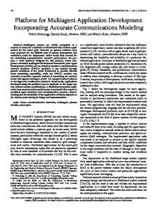
The Proactive Layer is the lowest layer, and is in charge of day-to-day system operation according to a Day-to-Day Plan (Phase I, see Fig. 2). The conceptual input, i.e., voltage and reactive power, are collected by the Interface, and forwarded to the Proactive Layer; BAs work on this layer and monitor these inputs. If any fault is detected, the Reactive Layer (middle layer) will be activated. BAs will work on the Reactive Layer and try to restore the physical bus alone according to their Countermeasure Plans (Phase II). A BA’s Countermeasure Plan contains the actions which the BA can perform to restore the system from faults [12]. If the faults are serious and the bus cannot be restored by the BA alone, then the Social Layer will be activated (Phase III). A CA firstly constructs a group and tries to restore the bus locally. The CA will control the decision-making process and the task allocation process. The group size is dynamically modified according to the complexity of the faults. Each group member’s Countermeasure Plan will be considered by the group leader. The conflicts, such as interest conflicts, belief conflicts, and behavior conflicts, between group members are solved through agent negotiations [13]. The group leader will consider each member’s ability and allocate execution proposals. The execution proposal will be forwarded to the Reactive Layer to adapt each BA’s individual behavior (Phase IV). After the system is restored, the group will be destroyed and all BAs returns to the Proactive Layer (Phase V). Phases II, III, and IV will be repeated when the CA fails to get a solution in its group and a bigger group is needed. In the extreme case, when the faults are fatal, the group size will be enlarged to the whole power system, and a global solution will be generated.
II. PRINCIPAL SYSTEM CONCEPT In Fig. 1, the architecture of the proposed MAS is displayed. In general, the proposed MAS contains three layers, i.e., Proactive Layer, Reactive Layer, and Social Layer, and two types of agents, i.e., BA and CA. In Fig. 2, the time frame for both BAs and CAs in each layers are displayed.
III. MULTI-AGENT SYSTEM A. Bus Agents A BA is a static agent, and is permanently associated with a physical bus. A BA will be eliminated only when its corresponding physical bus is removed from the power system. A BA
734
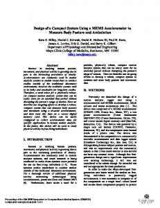
Fig. 3. IEEE 30-bus power system.
IEEE TRANSACTIONS ON POWER SYSTEMS, VOL. 27, NO. 2, MAY 2012
indicate all cases in the Plan component, and each case in the li.A brary is defined as records a fact that ever executed an action in case milliseconds after a fault (i.e., fault reactive power is and voltage is ) was detected, and the action successfully and voltage to . Suprestore Bus ’s reactive power to is detected by at time , pose a fault in order to select a reasonable countermeasure from its Plans, firstly retrieve its Plans and evaluate each case in the Plans according to (1). The purpose of Equation 1 is to calculate the by considering difference between the fault and the case the time, the magnitude of the fault, and the effect of the action:
(1)
Fig. 4. Bus agent.
monitors the status of the physical bus, and controls the behaviors of the physical bus. For example, in Fig. 3, we display the IEEE 30-bus power system [14], and each physical bus is allocated a BA. BA1 is associated with GLEN LYN Generator, and can control the generator’s output power. In order to effectively implement BAs, we use the Belief-Desire-Intention (BDI) agent model. The BDI agent model is a software model for intelligent agents, and provides a mechanism for agents to select plans through deliberation. Beliefs represent the informational state of the agent and the world. Desires represent the motivational state of the agent. They represent objectives or situations that the agent would like to accomplish or bring about. Intentions represent the deliberative state of an agent—what the agent has chosen to do. Intentions are desires to which the agent has to do some extent committed. is illustrated. Firstly, the In Fig. 4, the procedure of a Sensors component transfers the signal inputs from the power system to the conceptual input of the Belief Revision Function will construct the Belief component to component. The represent the existing status of the physical bus at time (i.e., and the voltage ) and the Desire comthe reactive power ponent to indicate the theoretical expectation on Bus . Secemploys the Filtering function to choose a practical ondly, status that Bus should be by comparing its beliefs and desires, and the Intentions component is generated (containing intenand voltage ). Then we employ the tion reactive power case-based reasoning (CBR) as the internal logic to perform the action selection function, and the selected actions will be exe’s intentions. If faults are detected, the Reaccuted to fulfill tive Layer will be triggered and countermeasure actions will be selected from Plans to restore the bus. Let
where is the time when the evaluation is performed and is the normalization function. is most similar one as the fault Suppose case , then its action is selected and executed by , and the consequent results [i.e., reactive power ( ) and voltage ( )] are recorded. A new case is added ’s Plans. If the results satisfy ’s Intentions, into will turn itself back to the Proactive Layer. Otherwise, if the results do not satisfy ’s Intentions, will ask help from a CA and the Social Layer will be activated. B. Coordination Agents A CA works on the Social Layer, and is not fixed to any physical bus. A CA does not permanently exist, but is created under a request and is eliminated when its tasks are completed. Our proposed CA has three features which make its differences from related work [10], [12]. 1) It can reduce the system cost. A CA will be created only when a BA cannot solve the problem caused by a system fault alone. After the problem is solved, the CA will be eliminated. In Fig. 3, when BA23 detects a fault but cannot solve the problem, CA1 is created under the request of BA23. CA1 controls BA23 and BA23’s neighbors (i.e., BA15 and BA24), and tries to solve the problem within this group. After the problem is solved, CA1 will release all controlled agents and CA1 will be eliminated as well. 2) More than one CA can work concurrently on multiple heterogeneous buses for solving different problems. In Fig. 3, when CA1 is solving a problem through coordinating BA15, BA23, and BA24, CA2 is working on another issue by managing BA1, BA2, and BA3. These BAs and CAs work on different facilities and have different functionalities. 3) The proposed CAs are robust and scalable for solving problems in different complexities. In Fig. 3, when CA2 cannot solve a problem within the existing group (contains BA1, BA2, and BA3), CA3 is created under the request of CA2. Then CA3 will coordinate CA2, (but CA2 still controls its original group members), and also coordinate all neighbors of CA2’s group members. CA3 will lead the new group to solve the problem.
REN et al.: CONCEPTUAL DESIGN OF A MULTI-AGENT SYSTEM
735
Fig. 5. Coordination agent.
In the extreme case, a top CA will be created to control all other agents, and the global solution will be provided. In Fig. 5, the coordination procedure of CAs is illustrated. Firstly, under the request of a Servant Agent (SA) (a BA or a CA), a CA will be created and performs a team forming process to generate a group (the detail about team forming will be introduced in Section III-C), and the CA becomes a Master Agent (MA) to control all group members. Then the CA will collect information from its SAs. By combining all SAs’ plans and possible behaviors, the Plan Set and the Action Set can be created. Thirdly, the CA will perform a Practical Reasoning process to analyze the fault reported by its SA and to find a countermeasure based on the collected information. We still employ the case-based reasoning for this purpose. Let be the Plan Set, where includes plans from . Let be the Action Set, where indicates actions can fulfill. Suppose fails to solve the problem . will cased by a fault alone, and request a help from , and its counterreport the original fault measures and consequent results [i.e., ] to . Then will forward time to its SAs, and request each SA to provide a norperiod to indicate how it is affected by the fault malized value reported and ’s actions. is calculated by considering is directly impacted by , and defined in (2): how
(2) where at time
and and , respectively. are defined as follows:
indicate ,
’s status , and
(3) otherwise.
(4)
ranks the SAs according to the values, and Then values are smaller than a predefined picks up the SAs whose
will perform an acthreshold. After that, each selected tion selection process based on the result of [ , , refer to (1) and Section III-A for details], respectively. Because different SAs may have different knowledge and action plans, conflicts may happen during will perform as a their cooperations. In such a case, the mediator to exchange intentions between the selected SAs, and adapt their intentions gradually until the conflicts are resolved. Such process is named as Negotiation. Generally, in order to will order reach an agreement during the negotiation, the SAs to concede their intentions between the most expected bus status and the existing bus status according to the time past and the bus’ priority. Because of page limitation, the principle of agent negotiation can be gotten in the literatures [13], [15] or our previous work [16], [17]. Lastly, the Task Allocation process allocates tasks to SAs according to the action selection results and the negotiation outcomes (if applicable). After SAs fulfill their tasks, the feedback from the physical bus will indicate the will be elimiperformance. If the problem is solved, the will request nated and all SAs will be released. Otherwise, helps from another Coordination Agent and a bigger group will be created (see Section III-C for details). Such a process is repeated until the problem is solved or the group size reaches the maximum number, i.e., including all BAs. C. Dynamic Team Forming Mechanism Let Agent be an agent in the MAS, if Agent is a BA, set NP will include all agents which have a direct connection between Agent ; and if Agent is a CA, set NP will include all agents which have a direct connection with any agent controlled by Agent . Suppose that a fault happens and is detected by Agent , Agent will try to solve the problem without helps from any other agents. However, if Agent fails to solve the problem alone, a Team Forming Algorithm (TFA) will be per. Then formed. Firstly, Agent asks help from a CA, i.e., will create a group (i.e., Group G), and add Agent as a . Secondly, will contact Agent group member, i.e., ’s neighbors, i.e., all agents in set NP, for team forming purpose, and wait for their responses. If a neighbor of Agent is not ’s controlled by any other agents, this neighbor will reply to request, and becomes a member of Group G. In the case that a neighbor of Agent is already controlled by another agent, this ’s request to its controller, and let the neighbor will forward controller decide whether they will join Group G. Lastly, when gets all responses from all Agent ’s neighbors, Group G is finalized. Then will behave as a MA and controls all agents in group G. The result of TFA is a hierarchical MAS is the controller. By comparison with simply structure, and adding more BAs to the same group and control the group using just one CA, the proposed TFA has the following merits. 1) The proposed TFA generates a hierarchical structured MAS, which can effectively share work loads among CAs according to fault complexities, so as to improve the whole system’s efficiency. 2) The proposed TFA provides the system with the ability to solve parallel problems, which is difficult to be fulfilled in single CA structure. 3) The proposed TFA is more robust in the case when a CA fails, and can prevent the failure of the whole system (see
736
IEEE TRANSACTIONS ON POWER SYSTEMS, VOL. 27, NO. 2, MAY 2012
Team Reforming Algorithm for details 2). In Algorithm 1, we formally define the TFA. Algorithm 1: Team forming algorithm 1: Input: Agent
(
),
2: Output: A new CA
and its controlled Group G
3: create a new CA 4: set
to
, G to , and
to
5: 6: for each neighbor agent (Agent 7: 8:
) of
do
then
if set
to
9: 10:
else
11: 12:
while
13:
set
do to
14:
end while
15:
set
to
16: 17:
end if
18: end for 19: return CA
and Group G
In order to check the dominance relationship of an agent , a query with response requirement is sent to Agent . Agent will reply ’MA’ if it is a controller, or ’ ’ if it is controlled by Agent , then another query will be further sent to Agent . Such a process is repeated until an agent replies ’MA’, and the dominance relationship is got by recording the sequence of replies. For example, suppose we are going to check the dominance of BA3 in Fig. 3, the following steps are performed: , ; 1) , ; 2) 3) , ; 4) (where indicates Agent return is controlled by Agent ). Theoretically, a CA can control any number of agents. A CA’s problem solving ability will be improved as its group member increases. That is because with more group members, a CA can collect more information about a power system, and organize more complex operations within the group. For instance, CCS can be considered as an extreme case that a CA dominates a group containing all agents in a power system. With a large group members, CCS can produce the global optimal solution, but will spend much longer time. So getting the balance between effectiveness and efficiency is very important. Therefore, usually the agent number in a group
is small at the beginning, and gradually increased. Generally, the proposed method is scalable. However the complexity of interconnections in a large scale power system will impact the performance of the proposed TFA. If a power system contains too many interconnections, each BA will have a large number of directly connected agents, so as the agent number in each group will be large and the group controller will spend a long time to plan the countermeasures and organize each group members (i.e., similar as the disadvantages in CCS). On the other hand, if the interconnections in a power system are few and BAs have very limited directly linked neighbors, many CAs will be created before an effective solution is generated. This is because few new agents will be added to an existing group. Each time a new CA is created, the new CA may not have significant improvement on its knowledge for the problem solving, and hence will keep on creating new CAs until an effective solution is proposed. According to our experience, if a bus has only one connection with its neighbor, the team forming process may become time-consuming; and if a bus has more than 6 connections, the decision-making process may become time-consuming. Solving such a problem will be one of our focuses in the further research. However, during the TFA process, an agent may fail and become unreachable. In order to solve such an issue, a Team Reforming Algorithm (TRA) is proposed. Generally, if a controller agent notices that a controlled agent is unreachable, the controller agent will eliminate the controlled agent from its group straightway. If the controlled agent is the one who originally detects the fault (a BA) or forwards the fault (a CA) to the controller agent, then the controller agent will destroy the group. The controlled agent will perform the TFA process to request a help from another CA to solve the problem. If a controlled agent finds that its controller agent becomes unreachable, the controlled agent will leave the controller agent’s group, and turn itself back to an MA. Then the controlled agent will perform the TFA process again if necessary. The TRA is shown in Algorithm 2. Algorithm 2: Team reforming algorithm (TRA) 1: Input: CA , ’s controlled group G, and ’s controller CA 2: Output: The CA 3: for each agent 4:
and its Group G will be reformed in Group G do
if
then
5: 6:
set
7:
if
to then
8: 9:
if
then
10: 11:
else
12:
if
is CA then
REN et al.: CONCEPTUAL DESIGN OF A MULTI-AGENT SYSTEM
measures introduced in [18] are compared. The 30-bus system is simulated by using the MATPOWER package [19] on Matlab, and all agents are implemented by using the Jack Agent Software which can allow many agents to be simulated and includes interagent communication. During the simulation, the data generated from the Matlab on each physical bus are firstly recorded by Microsoft Excel files, and read by our agents automatically. After agents make decisions on the following actions, the adjustments on each physical bus will be delivered to the corresponding Excel files. Then the Matlab updates the settings on each physical bus according to the Excel files, and re-generates new simulation results. Finally, by recording these simulation results continuously, the simulation curve for each physical bus can be generated. In this section, three cases are investigated. The first case mimics a situation where only one bus has a fault and the load shedding operation is not necessary to restore the fault. The second case mimics a situation where a generator bus has a fatal fault and the load shedding operation is necessary. The third case mimics a situation where two buses have faults concurrently. Through the case studies, the dynamic managing ability of the proposed MAS is demonstrated in the aspect of restoring a power system.
13: 14:
end if
15:
end if
16: 17:
end if end if
18: end for 19: if
then
20:
set
21:
if
to then
22: 23:
else
24: 25:
end if
26: end if After a group of agents (Group G) successfully solves a system problem, the group will be eliminated to reduce the be the group leader, the TDA is system operation cost. Let defined in Algorithm 3. Generally, TDA is a recursive algorithm solves all allocated problems, and is and is activated when not controlled by any agent. Firstly, will release all agents in Group G, and then be eliminated. Secondly, if a member agent of Group G is a CA, the above process will be applied again on this member agent. Such a recursive procedure will be continued until all agents in the hierarchical structure controlled are released or a CA’s tasks are not complete. by Algorithm 3: Team dismissing algorithm (TDA) 1: Input: A CA
and its controlled group G
2: Output: The CA
and Group G will be eliminated
3: if 4: 5:
and for each agent
then
in Group G do
set
to
6: 7:
if
is CA then
8: 9: 10:
737
end if end for
11: 12: end if IV. CASE STUDIES The IEEE 30-bus power system [14] (Fig. 3) is used to test the proposed MAS, and the restoration results with the counter-
A. Case I Case I mimics the situation that only one bus has a fault, and the load shedding operation is not necessary for restoring the system. We assume that Bus 3 is broken and the countermeasures introduced in [18] is employed to restore the system. The countermeasures are chosen to avoid voltage collapse due to the restoration in generation reactive power output which is around 50 s. Typical countermeasures against voltage drop such as sc voltage increase, generation and load tap change operation are carried out in the first 30 s and if the countermeasure has not caused the voltage to recover, load shedding is actuated at 30 s giving a manager of 20 s before the reactive power of the first generator is rescheduled (which can lead to fast voltage collapse region). Such countermeasures are centralized controls, and must have global view of the power system. The countermeasures are displayed in Table I. In Step 1, the generator voltage in Bus11 is increased. In Steps 2–3, the transformer ratios in Bus4 and Bus6 are modified. In Steps 4–5, Bus30 and Bus29 perform load shedding operation. We monitor the voltage of Bus30 and the power of Bus11 in Fig. 6. It can be seen that without countermeasures, the power system will collapse, i.e., Bus30’s voltage will drop to zero, and Bus11’s generator will be damaged, and with the traditional protection introduced in [18], Bus30’s voltage is kept around 1.02 pu, and Bus11’s reactive power is kept around 20 Mvar. Even though the traditional countermeasures can solve the system faults, and restore the system from vulnerable state, several components (i.e., generators and transformers) are impacted, and the load shedding operation needs to be performed. In Table II, the proposed MAS countermeasures are displayed. Firstly, BA3 detects the fault, and activates the Reactive Layer and Social Layer. Then CA1 is created to solve the , but it fails. Immediately, a higher problem within Group . level CA2 is created to solve the problem within Group Finally, CA2 orders BA5 to modify its generator’s voltage,
738
IEEE TRANSACTIONS ON POWER SYSTEMS, VOL. 27, NO. 2, MAY 2012
Fig. 6. Restoration results comparison (Case I).
Fig. 7. Restoration results comparison (Case II).
TABLE I TRADITIONAL COUNTERMEASURES
TABLE III PROPOSED MAS COUNTERMEASURES (CASE II)
TABLE II PROPOSED MAS COUNTERMEASURES (CASE I)
and the problem is solved within Group . After the power system become stable, CA1 and CA2 are eliminated, and all BAs are back to the Proactive Layer. The restoration results are compared with the traditional approach’s results in Fig. 6. It can be seen that by using the proposed MAS, Bus30’s voltage is kept around 0.99 pu, and Bus11’s reactive power is kept around 17 Mvar. Although Bus30’s voltage is not restored to the same level, the proposed MAS can also prevent the power system from collapse. Furthermore, the proposed MAS only modifies the generator voltage of Bus5, and does not perform a load shedding operation, and hence minimizes the impact to the system users. Also, the traditional countermeasures spent 30 s to restore the system, while our proposed MAS only spent 7 s to solve the fault in a local group. B. Case II Case II simulates a situation that a generator bus (i.e., Bus2) has a problem and the generator is disconnected. In such a case, the load shedding operation is necessary in order to prevent system collapse. Firstly, we employ the traditional countermeasures (see Table I) to restore the power system, and the results are displayed in Fig. 7. It can be seen that with such a protection, the power system is saved. Bus30’s voltage is increased to 0.9 pu, and Bus11’s reactive power is kept round 18 Mvar. The proposed MAS countermeasures are displayed in Table III. BA2 firstly detected the fault and asked help from CA1. CA1 ordered BA1 and BA5 to increase their generators’ voltage and BA4 and BA6 to decrease their transformers’ ratio in Step 4. However, such a rescue failed and hence CA2 was generated. In Step 6, CA2 ordered BA13 to increase its generator’s voltage and BA28 to decrease its transformer’s ratio, but
it cannot stop the system collapse as well. Under the request of CA2, CA3 controlled more BAs and ordered BA11 to increase its voltage. Such an operation failed as well, and CA4 cannot perform any new operation to stop the system collapse. Finally, CA5 was created to control all BAs and CAs in the system. Because CA5 had the global view of the system, so it ordered BA29 and BA30 to perform the load shedding operation. The system was saved and prevented from collapse. It can be seen in Fig. 7 that before the load shedding operation was performed, even though several operations was performed to rescue the power system, BA11’s power dropped dramatically. After the load shedding operation was performed by CA5, BA11’s power was recovered and BA30’s voltage became stable. Our proposed MAS spent similar time as the traditional countermeasures to solve the fault in Case II. The simulation results indicates that our proposed MAS approach can also perform the load shedding operation when it is needed. C. Case III Case III mimics a more complex situation, namely that two faults occur at the same time in a power system. The connection between Bus2 and Bus6 and the connection between Bus24 and Bus25 are broken. Initially, we still employ the traditional countermeasures (see Table I) to restore the power system, and the results are displayed in Fig. 8. It can be seen that with such a protection, the power system is saved. Bus30’s voltage is increased to 1 pu, and Bus11’s reactive power is kept round 20
REN et al.: CONCEPTUAL DESIGN OF A MULTI-AGENT SYSTEM
Fig. 8. Restoration results comparison (Case III).
TABLE IV PROPOSED MAS COUNTERMEASURES (CASE III)
Mvar. However, as the problem in Case I, the traditional countermeasures require a centralized controller and a global system view, so its efficiency is decreased. Also, the traditional countermeasures will significantly impact system users because of the load shedding operation. In Table IV, the proposed MAS countermeasures are listed. When faults happen in Bus6 and Bus24, BA6 and BA24 detect faults, respectively. Firstly, both of them try to solve the problem alone, but both fail. Then they ask for help from CAs. CA1 con, and solves its problem by ordering BA2 to introls Group crease generator voltage in Step 4. At the same time, because CA2 cannot solve its problem, and it requests help from CA3. is released and CA3 orders both BA10 and In Step 5, Group BA27 to increase their transformer ratios, and the problem is solved. Finally, CA3 and CA2 are eliminated in sequence. The restoration results are illustrated in Fig. 8. It can be seen that our MAS also solves the two concurrent system faults using only local system views, and keeps Bus30’s voltage around 1 pu and Bus11’s reactive power around 17 Mvar. Obviously, the restoration efficiency is increased, and the impact on system users is decreased. Also, our proposed MAS only spent 13 s to restore the system by using two local groups, while the traditional countermeasures spent 30 s and the system global view was also needed.
V. RELATED WORK In this section, some related work is discussed and compared with our approach. Liu et al. [20] proposed a Strategic Power Infrastructure Defense (SPID) system to prevent catastrophic failures in power systems. The principle of SPID is to provide self-healing and adaptive reconfiguration capabilities for power grids based on wide-area system vulnerability assessment. A three-layer hybrid multi-agent system model was proposed to
739
fulfill self-healing strategies, i.e., the reactive layer, the coordination layer, and the deliberative layer. Even though SPID employs distributed agents, the architecture of SPID is static. Nagata et al. proposed a multi-agent approach for decentralized power system restoration in a distribution system network [10]. The load agent collects information about the power system, and the feeder agent controls the entire restoration process in accordance with the priority in the restoration strategy. However, their approach has a difficulty to provide a global solution for a catastrophic failure. Solanki et al. proposed a distributed multiagent system to analyze faults in a power system, and to restore the system after faults [1]. When a fault is detected by a load agent, an alert message is sent to generator agents. Then generator agents try to restore the fault by sending their remaining available transfer capacity to the problem load agent by passing through switch agents. However, their system only considers to control generators’ actions, but does not involve other facilities. Lin et al. proposed a centralized multi-agent system to model the power distribution between substations and end-users[21]. The distribution feeders and substation transformers are modeled by FCB agent and MTR agent, respectively. When a fault happens in an end-user, the FCB agent firstly allocates the fault by checking both the upstream and downstream switches’ current readings. Then restoration requirements are forwarded to the MTR agent. The MTR agent will perform a heuristic reasoning process to decide which loads should be restored or shed based on capacities of transformers and feeders, and the priorities of each load. Finally, the power will be transferred to the problem loads through valid feeders, and the distribution system can be restored. By comparison with the above work, our proposed multi-agent system has three merits. 1) Our proposed multi-agent system consists of three layers and manages power systems from day-to-day operations to dynamical faults restoration. 2) Our proposed multi-agent system uses DTFM to dynamically modify the system architecture. Distributed architectures are generated to perform normal operations and/or to restore the system by using individual agents, and hierarchical architectures are created to provide global solutions for faults. 3) Through dynamically adjusting the system architecture and the number of agents, our proposed multi-agent system can trade-off the system cost and the system efficiency. VI. CONCLUSION AND FUTURE WORK In this paper, a conceptual MAS design is proposed for autonomous power systems management and restoration. The Bus Agent was introduced to control each individual, physical bus in a power system, and the Coordination Agent was introduced to manage behaviors of Bus Agents. A dynamic team forming mechanism was proposed for agent coordination purposes. The architecture of the proposed MAS is changeable, and is dynamically and automatically modified according to power system status. The simulation results demonstrated the feasibility of the proposed MAS. Our future work on this research will focus on implementation of the MAS in a real-world application and testing the system in more complex scenarios.
740
IEEE TRANSACTIONS ON POWER SYSTEMS, VOL. 27, NO. 2, MAY 2012
REFERENCES [1] J. Solanki, S. Khushalani, and N. Schulz, “A multi-agent solution to distribution systems restoration,” IEEE Trans. Power Syst., vol. 22, no. 3, pp. 1026–1034, Aug. 2007. [2] S. McArthur, E. Davidson, V. Catterson, A. Dimeas, N. Hatziargyriou, F. Ponci, and T. Funabashi, “Multi-agent systems for power engineering applications Part I: Concepts, approaches, and technical challenges,” IEEE Trans. Power Syst., vol. 22, no. 4, pp. 1743–1752, Nov. 2007. [3] J. Jung, C. Liu, S. Tanimoto, and V. Vittal, “Adaptation in load shedding under vulnerable operating conditions,” IEEE Trans. Power Syst., vol. 17, no. 4, pp. 1199–1205, Nov. 2002. [4] T. Nagata, H. Watanabe, M. Ohno, and H. Sasaki, “A multi-agent approach to power system restoration,” in Proc. Int. Conf. Power System Technology, 2000, vol. 3, pp. 1551–1556. [5] D. Coury, J. Thorp, and K. Hopkinson, “Agent technology applied to adaptive relay setting for multi-terminallines,” in Proc. IEEE Power Eng. Soc. Summer Meeting, 2000, pp. 1196–1201. [6] S. Srivastava, H. Xiao, and K. Butler-Purry, “Multi-agent system for automated service restoration of shipboard power systems,” in Proc. 15th Int. Conf. Computer Applications in Industry and Engineering, 2002, pp. 119–123. [7] M. Nordman and M. Lehtonen, “An agent concept for managing electrical distribution networks,” IEEE Trans. Power Del., vol. 20, no. 2, pt. 1, pp. 696–703, Apr. 2005. [8] M. Nordman and M. Lehtonen, “Distributed agent-based state estimation for electrical distribution networks,” IEEE Trans. Power Syst., vol. 20, no. 2, pp. 652–658, May 2005. [9] T. Nagata, H. Fujita, and H. Sasaki, “Decentralized approach to normal operations for power system network,” in Proc. 13th Int. Conf. Intelligent Systems Application to Power Systems, 2005, pp. 407–412. [10] T. Nagata, Y. Tao, H. Sasaki, and H. Fujita, “A multiagent approach to distribution system restoration,” Elect. Eng. Japan, vol. 152, no. 3, pp. 21–28, 2005. [11] J. Kodama, T. Hamagami, H. Shinji, T. Tanabe, T. Funabashi, and H. Hirata, “Multi-agent-based autonomous power distribution network restoration using contract net protocol,” Elect. Eng. Japan, vol. 166, no. 4, pp. 56–63, 2009. [12] J. D. L. Ree, Y. Liu, L. Mili, A. Phadke, and L. DaSilva, “Catastrophic failures in power systems: Causes, analyses, and countermeasures,” Proc. IEEE, vol. 93, no. 5, pp. 956–964, May 2005.
[13] H. Wedde, S. Lehnhoff, E. Handschin, and O. Krause, “Real-time multi-agent support for decentralized management of electric power,” in Proc. 18th Euromicro Conf. Real-Time Systems, 2006, p. 9. [14] University of Washington, College of Engineering, Electrical Engineering, 2008. [Online]. Available: http://www.ee.washington.edu/research/pstca/. [15] S. Kraus, Strategic Negotiation in Multiagent Environments. Cambridge, MA: MIT Press, 2001. [16] F. Ren, K. Sim, and M. Zhang, “Market-driven agents with uncertain and dynamic outside options,” in Proc. 6th Int. Conf. Autonomous Agents and Multi-Agent Systems (AAMAS07), 2007, pp. 721–723. [17] F. Ren, M. Zhang, C. Miao, and Z. Shen, “A market-based multi-issue negotiation model considering multiple preferences in dynamic E-marketplaces,” in Proc. 12th Int. Conf. Principles of Practice in MultiAgent Systems (PRIMA09), 2009, pp. 1–16. [18] W. Lachs and D. Sutanto, “Voltage instability in interconnected power systems: A simulation approach,” IEEE Trans. Power Syst., vol. 7, no. 2, pp. 753–761, May 1992. [19] R. Zimmerman, C. Murillo-Sánchez, and D. Gan, MATPOWER: A MATLAB Power System Simulation Package. [Online]. Available: http://www.pserc.cornell.edu/matpower/. [20] C. Liu, J. Jung, G. Heydt, V. Vittal, and A. Phadke, “The strategic power infrastructure defense (SPID) system. A conceptual design,” IEEE Control Syst. Mag., vol. 20, no. 4, pp. 40–52, Aug. 2000. [21] C. Lin, C. Chen, T. Ku, C. Tsai, and C. Ho, “A multiagent-based distribution automation system for service restoration of fault contingencies,” Eur. Trans. Elect. Power, vol. 21, no. 1, pp. 239–253, 2011. Fenghui Ren, photo and biography unavailable at time of publication.
Minjie Zhang, photo and biography unavailable at time of publication.
Danny Soetanto, photo and biography unavailable at time of publication.
XiaoDong Su, photo and biography unavailable at time of publication.