ease the building of custom views/representations and tooling for those con- ceptual models; ..... Combined with AMW [55] it supports the definition of custom ar-.
Conceptual interoperability through Models Federation Christophe Guychard1 , Sylvain Guerin1 , Ali Koudri2 , Antoine Beugnard3 , and Fabien Dagnat3 1
3
Openflexo {christophe.guychard,sylvain.guerin}@openflexo.org http://www.openflexo.org 2 THALES {ali.koudri}@thalesgroup.com http://www.thalesgroup.com Telecom Bretagne {antoine.beugnard,fabien.dagnat}@telecom-bretagne.eu http://www.telecom-bretagne.eu
Abstract. Successful architecting of complex systems requires reconciling heterogeneous viewpoints expressed by the stakeholders involved in the development process, including domain and technical experts, users and managers. Most of the time, each concern is analyzed by experts using well-fitted specific tools to produce their point of view on a solution. This results in a set of models with various technical spaces, formalisms and paradigms. Ensuring global consistency, maintaining traceability and building crossconcerns views in that context is challenging. In order to address this issues, we initiated the development of a tooling that provides support for building conceptual views expanding upon existing models and tools. It has been applied to uses cases such as: model composition across technical spaces, heterogeneous (meta)models alignment and keeping models in sync. In this paper, we introduce the models federation approach to conceptual interoperability that drives the development of our innovative modeling engine.
1
Introduction
From requirements to implementation, the analysis and development of complex systems involves the execution of several design and analysis activities relying on various domain expertises. Architects are responsible for ensuring the global consistency and understanding of the system. To do so, they have to integrate every expert’s and stakeholder’s viewpoints [1]. Those highly collaborative processes need to support agile methodologies to manage the co-evolution and reconciliation of the various modeling concerns. Every concern is analyzed and studied by domain experts using specific tools to design and produce their point of view on a solution. Their work results in a set of models (text, graphics, program, etc) with various formalisms and paradigms well-fitted to their concern [2]. With this wide range of tools and models, the
2
Authors Suppressed Due to Excessive Length
challenge of architects is to ensure a global consistency [3] in order to produce a correct-by-construction implementation of the system. Whatever the system under study might be, from pure technical [4,5] to socio-technical [6] systems, the same observations can be made. From embedded system design to enterprise architecture modeling, any architect faces the same situation: – multiplicity of views: any stakeholder of the system needs a set of custom views, expressing his viewpoint, to be sure that each of his concerns has been documented; – multiplicity of concerns: the space of functional and non-functional concerns often does not fit with the organization of views, as any view on the system might address several concerns; – multiplicity of models: depending on the modeling intention, one has to choose the right formalisms and representations; – heterogeneity of modeling artifacts: those can come in the form of structured diagrams or text (requirements), drawings, spreadsheets, process-flow data,... Traditional approaches considering that situation are typically oriented toward integration [7,4,8,9,10], composition [11,12,13], or unification [14,15,16,17]. As a consequence, most of them aim at providing a single (meta-)model, tool or modeling artifact that covers the whole set of concerns to be addressed. Yet, this does not help in dealing with legacy models, heterogeneous technical spaces, or in providing the architect with tools to build customized conceptual views of the system involving various artifacts. In this paper, we propose a new pragmatic approach to conceptual interoperability, oriented towards the federation of models. Based on our field experience, we are developing a unique infrastructure featuring abilities to build conceptual views that expands upon several heterogeneous modeling artifacts. It has been architected with the following goals in mind: – provide a conceptual modeling layer that pushes back technical spaces frontiers; – ease the building of custom views/representations and tooling for those conceptual models; – federate models coming from different technical spaces, allowing the conciliation of data produced by several specialty tools; – improve the capabilities of capitalization and reuse of conceptual models and their related representations (views/viewpoints definition); – support a collaborative modeling process by providing model sharing features while enabling views customization; – go beyond the limitations of traditional strict-meta-modeling environments. With the achievement of these goals, we expect strong impacts on modeling capabilities. Among others, the following expected features are of great importance for organizations developing complex products: improved reuse of
Conceptual interoperability through Models Federation
3
(meta)models and legacy, improved horizontal (model synchronization, conceptual alignment) and vertical traceability (detailed analysis, refinement), improved modeling tools flexibility and maintainability. In the following, we introduce the needs that our clients and partners expressed (sections 2), before exposing our view on models federation (section 3). We will briefly expose actual use cases (section 4), in which the Openflexo modeling infrastructure (section 5) has been used. Then, we compare our approach to previous works (section 6), before concluding with some perspectives of this work.
2
Needs
The development of complex systems requires complex processes involving several experts, each coming with its own viewpoints over the system under study. Examples of viewpoint are: operation analyses, human factors, safety, security, performance, training, building, etc. We briefly discuss three approaches to tackle these issues: domain specific modeling, model-based system engineering and architecture frameworks. 2.1
Domain Specific Modeling
Domain Specific Modeling [18] has been widely applied to provide dedicated tools to domain experts. On the plus side, these tools accelerate the requirements engineering process, the users can better understand the models because they are represented in domain-specific terms, the restriction of semantic scope of modeling language (the number of semantics variations to deal with is small compared with generalpurpose languages), hence a better support for generating implementations from models. One of the main problems with domain-specific modeling languages is the “Tower of Babel” [18][19] problem in which the proliferation of different languages reduces the value of models as communication vehicles. If the burden of defining a new DSML becomes considerably lower, we will probably see a large number of DSMLs created and used. The situation will be similar to the one faced with the use of XML-Dialects : many Dialects will appear and their interoperability or translation between them will be a major problem. From that situation, emerges the need to better coordinate modeling languages [20]. At least, we have to provide methods and tools to better support co-evolution [21], synchronization [22] and combination [23]. 2.2
Model Based System Engineering
Instead of defining domain specific models, another approach consists in choosing a general purpose modeling environment such as the one proposed by the
4
Authors Suppressed Due to Excessive Length
OMG with MOF [24] and UML[17] through Model Driven Architecture (or more generally Model Driven Engineering). But, the strong partitioning between domain’s expertises causes technological breakpoints [5,9]. Those are at the source of misalignment and frictions when data is both conceptually and technically captured by several tools. This problem must be managed in a ad-hoc manner and its resolution generally leads in a misuse of tools. For example, the engineering of radar systems involves the definition of a system architecture and signal processing algorithms. The definition of an architecture is usually performed using an in-house tool that supports the vocabulary of the domain (Phased Array Antenna, Pulse Compression, Radar Cross Section, etc.) while the definition of the algorithms use mathematical tools providing ordinary differential equations solvers and matrix manipulation operations like Matlab. Using unified languages like UML or its derivatives (SysML, MARTE, etc.) is not satisfying because this requires contortions from both system architect and algorithmists. Indeed, the projection of domain concepts onto a general purpose modeling language is not easy since this generally imposes workarounds and semantic restrictions or adaptations. Thus, most manufacturers have adopted pragmatic approaches mixing specialty tools and general purpose modeling languages [9]. And they are now looking for solutions to better integrate their tool-chains [4]. Our experience, combined with the inputs of the iFest [25] research program, advocates for a complimentary approach to traditional tools integration approaches. In particular, specific issues are raised when transitioning from one engineering phase to another (e.g. from requirements analysis to structural design,or functional analysis to component allocation). Those related to traceability [26,27], round-trip support [28,29], and conceptual alignment [30,3], are of particular interest to us. From our perspective, they share common ground with DSML coordination (see previous section) and are quite similar to the ones we meet when aligning views in an architecture framework. 2.3
Architecture Frameworks
Architecture Frameworks (AF)[6,31] provide a way to organize the many views and models that are used to describe a given system. Lots of them have been proposed (4+1 [32],RM-ODP (ISO/IEC 10746) [33],MODAF [34], DODAF [35], TOGAF [36], FEAF, TEAF,...), that are more or less specific to a particular domain. Even when freedom is let to choose the representations, most of these approaches are mainly prescriptive and do not provide ways to extend the existing views or define new ones. Plus, they tend to be agnostic about the tooling to be used, even if some standardization efforts, such as UPDM [37,38] or VUML [39], are under way. Viewpoint modeling [40] is a similar approach that as emerged in the traditional system engineering community [5,41]. The ISO-IEC 42010:2011[42] standard has been proposed to document how to manage the integration of different
Conceptual interoperability through Models Federation
5
viewpoints into the same modeling space. We don’t know of any tooling supporting a complete implementation of the standard. The resulting situation is that enterprise and system architects are not yet provided with the required tooling to build their own custom architecture descriptions by assembling views from heterogeneous modeling artifacts. Another strong issue related to Architecture Frameworks/Multi-viewpoints models, is view alignment (or consistency) [3,2]. Most of the proposed standards do not provide any clue with how to manage conceptual alignment of views in an architecture description. As a result, one has to figure out its own rules and develop the related tooling to ensure consistency, such as in [43,44]. Furthermore, we don’t know of any existing approach that provide ways to ensure consistency across heterogeneous modeling artifacts and tools.
2.4
Synthesis
Manufacturers need methods for seamless and transparent integration of specialized representations and their tooling at low cost. Beyond data and representations integration, there is a need for a real separation of concerns allowing a consistent reasoning and a better design space exploration. Maintaining consistency between various prisms through which the system is studied needs formal foundations to support consistent reasoning and relevant querying (data mining, views extraction, information inferences). This requires the ability to define and maintain semantic traceability links between the artifacts produced by all the tools within a single modeling space. This includes inner domain traceability (refinement, derivation, versioning) or cross-domain traceability (between artifacts or between artifacts and process activities). For a radar system, we need to establish semantic links between the architecture built with a SysML tool and the algorithms defined in Matlab, and to define clearly the role of each model in relation with the intentions of the process stakeholders. We also need to map architecture model elements to the definition of process activities in order to support the orchestration and continuous maturity improvement of the development process. Capturing such semantic links is particularly tedious and fragile within a context assuming an open world approach. Indeed, scaling and concurrent development requires modeling space fragmentation [45] and sharing (partial loading of models). In this context, current proposals force experts to use tools that do not fit their needs in terms of business concepts, functionalities or even GUI. To summarize, current practice imposes the integration of several heterogeneous and unsynchronized viewpoints generating data friction and inconsistencies. Furthermore, each decision must be traced against requirements in order to support both horizontal (decomposition) and vertical traceability (refinement) even across technological spaces. Therefore, we need a framework to guide the architect while offering a better learning curve because more and more skills are required to develop complex systems.
6
Authors Suppressed Due to Excessive Length
3
Federating models
Regarding the issues described in the previous section, this section gives an overview of our work in order to offer more powerful modeling techniques suited to the user’s needs while ensuring a global consistency at the same time.
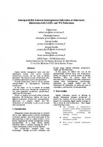
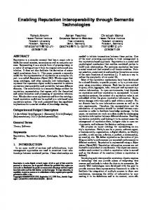
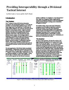
Fig. 1. Modeling environment organization.
3.1
Principles
Our paradigm shift relies on a separation of the modeling environment into three responsibilities or spaces (fig.1): – (center) an open and free conceptual modeling space, – (left) the designer interactions, – (right) projections in the technological or information spaces. In this article we focus on the two rightmost spaces and their connection: the information space is the source of heterogeneous models and the concept space is the place where the relationships among all that information is managed. The concept space is the location where models federation takes place: FlexoConcepts are defined as an assembly of information coming from other concepts or models stored in the information space. A set of concepts defines a VirtualModel that can be serialized back in the information space and hence used as a source of information.
Conceptual interoperability through Models Federation
7
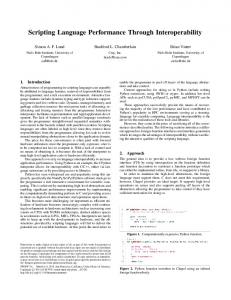
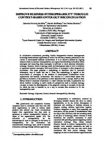
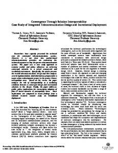
Fig. 2. Focus on the technological connectors.
A technological connector is used to allow the connection between a specific technology and our conceptual models as in fig.2. Technological connectors ensure the access for reading, writing and, if needed, synchronizing the pieces of information (resources). No copies are created. Those links are used by concept to define the consistency expected by the architects. The relationship is twoways: when something changes in the concept space, the information space may be updated and when something changes in the information space, the concept space is notified. 3.2
How models federation takes place?
Putting models federation at work is a two steps process : 1. design and tool the virtual models, that is: – define which are the relevant federated concepts, and from which kind of information they are built, – design the tooling and representations for those concepts. 2. instantiate virtual models by eventually connecting the conceptual models instances to (new or existing) resources from the information space. Two roles can identified in the process: – the tooling expert, which is mainly in charge of the first step, that is designing the tools, – the domain expert, which is the actual user of the designer tools and typically defines the modeling requirements.
8
Authors Suppressed Due to Excessive Length
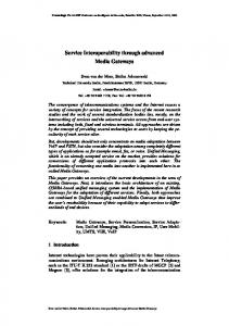
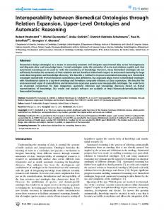
The VirtualModels designing process has to be collaborative, e.g.: federated concepts are defined by the domain expert and designed by the tooling expert. Our approach is essentially model-centric: most of the time, no single line of code is necessary to design a complete modeling environment. Thus, it is easier to support short iterations when designing or evolving the tools. Figure 3 illustrates how things take place at run-time. All the concepts introduced here are more precisely defined in the following.
Fig. 3. Models federation illustrated.
Concept Space is the actual core of the model federation engine, it provides the designer with a flexible environment where he can model easily any kind of things. It is where ”models federation” happens: it builds on and enriches existing information, allowing the user to define new concepts and enforce inter- and intra-conceptual consistency rules. A single unifying abstraction is offered: the FlexoConcept. Any other construct dedicated to conceptual modeling derives from it. The relevant concepts are defined by the domain expert, and the tooling expert designs them out of ModellingElement. An FlexoConcept might be seen as an n-ary relationship between some ModellingElements, carrying a given(contextual) semantics. In the context of a FlexoConcept definition, a ConceptRole assigns a name to a ModellingElement reference.
Conceptual interoperability through Models Federation
9
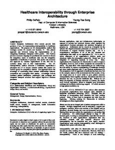
VirtualModel is the modeling space where the expert defines FlexoConcepts. A VirtualModel is a container for instances of FlexoConcepts. The VirtualModel has also the responsibility for the life cycle of contained FlexoConcepts. A VirtualModels may define graphical representations for concepts. In that particular case, the resulting drawing/diagram is considered as an additional federated information source. Thus, all federated models, independently of their structural form (graphics, free or structured text, database records,...), are considered evenly. The ModelSlot (red shapes in fig.2) is the part of the modeling infrastructure that provides a symbolic link to a Resource (source of information) in the InformationSpace. Using a given ModelSlot implies an interpretation for underlying source of information. The ModelSlot introspectively exposes structural and behavioral contents: the “types” of ModellingElements which may be manipulated in the ConceptSpace (the ConceptRole types), and the actions (the EditionAction types) which may be executed. The ModelSlot should also be considered as a formal contract in which the designer may rely on. A TypeAwareModelSlot is a specialized ModelSlot offering as source of information a model conform to a metamodel. The ModelSlot contract is carried by the metamodel conformance relationship. The connection maintained by a ModelSlot, may involve complex semantic translations and synchronizations. This conformance relationship is not a requirement for Openflexo infrastructure.
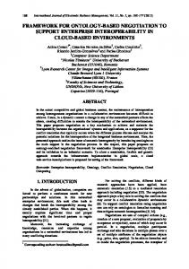
Fig. 4. Information Space Overview.
10
Authors Suppressed Due to Excessive Length
Information Space is the collection of databases, files and tools were the information is stored. In this context, any source of information is considered as a model that can be exposed to the Concept Space. This includes the whole set of modeling contents (models and metamodels) and languages that have been defined in many business contexts, using various supporting technologies. ModellingElements are exposed through technology adapters (model connectors) to the designer, and can be used to build new concepts. Those elements belong to some Resource, which is an actual source of information, interpreted by a model connector. The TechnologyAdapter is a special kind of connector, a software component handling a given technology. A TechnologyAdapter offers one or more ModelSlots, providing the designers with several possible interpretations of resource data. Figure 4 illustrates the overall structure of the information space at runtime. Resources are managed by ResourceCenters which do the binding between the actual source of information (file, database, bit-stream,...), and TechnologyAdapters. Those are responsible for the management of the resources life-cycle. The description of the global management of those elements is not in the scope of this paper. The focus here is on demonstrating our ability to connect to several technological spaces and to enable building federated concepts at the Concept Space level. In the next section, we introduce typical use cases in which our approach has been applied.
4
Use Cases
Our initial field experimentation have given us evidence of the potential of our approach. It has proved that it could adapt to a wide range of use cases including model synchronization, model mapping, and multi-paradigm modeling. All the use-cases introduced here were implemented using the Openflexo Modeling infrastructure (see section 5). 4.1
Model synchronization
In that case, the situation to fix is the following: – several different formalisms (Metamodels) are used to model the same information, – all targeting different intentions/communities, and tooled accordingly, – models might belong to heterogeneous technological spaces, – yet, all models have to be in accordance. At first sight, it might seem that a traditional transformation oriented (either point-to-point or hub-and-spoke) solution could be used to address the need. Yet, it would not provide features like:
Conceptual interoperability through Models Federation
11
– manipulation of all the models at the same time, using a single tooling; – independent tooling of federated concepts, e.g.: provide a graphical representation for federated concepts that can display synchronization status as in figure 7; – manipulation of the modeling space with partially synchronized or missing models; – support for interactive, ”element-by-element” synchronization decision. This list of additional abilities we can provide to the user is not exhaustive. We need to go further with the experimentation for discovering more. As an example, we envision original solutions for issues like: interactive and incremental synchronization, n-to-m models synchronization or co-evolution (models and metamodels evolving simultaneously). The whole industrial use-case that has been addressed is not available for publication. Thus, a simple example has been released, and published [46] to demonstrate the ability to synchronize two EMF models conforming to different metamodels.
Fig. 5. Tooling the ”City” federated concept.
12
Authors Suppressed Due to Excessive Length
Figure 5 illustrates how one can define and tool a federated concept using the Viewpoint Modeler. Here, it is a very simple ”City” FlexoConcept, that is built from two ConceptRoles4 , each pointing to a ModellingElement instances in one of the two models to synchronize. The tooling expert can define many kinds of manipulation primitives for the federated concept: CRUD operations, synchronization operations, transformations, ... Constraints can also be provided to ensure consistency between referenced ModellingElements. When all the federated concepts are defined, one can describe the synchronization procedures at the VirtualModel level. Figure 6 displays the HMI that we provide to the designer to do so.
Fig. 6. Defining the synchronization scheme.
The tooling expert can also define graphical representations for federated concepts, and provide ways to manipulate (such CRUD operations) them through the graphical view. E.g., figure 7 displays a graphical palette that provides tools to drop (i.e. create) additional instances of concepts. The behaviour of the tooling is completely defined at the VirtualModel or FlexoConcept level. For example, one can choose to implement a deletion behaviour that suppresses the shapes on the diagram and instances in one model but in the other one. 4
In former version of the tooling, the ConceptRole concept was named PatternRole, and FlexoConcept was named EditionPattern. Some refactoring is under way, but some part of the Viewpoint modeler HMI still expose the former names.
Conceptual interoperability through Models Federation
13
Fig. 7. Tooling the ”City” federated concept.
The full documentation, source code and metamodels of the examples are available online [46], and we are currently in the process of extending this simple one to demonstrate models synchronization across technological spaces. 4.2
Model mapping
In another industrial context, we had to design a workbench to capture ”transformations models”. The need was to support the collaborative definition of transformations from one tool targeting one expertise domain A, to another one supporting an expertise domain B. Both tools were used to model the same kind of information, but with very different perspectives. Several data models were provided for each domain, and the whole set of models, from both sides, had to be considered so that transformation specifications be correctly designed. This is quite a typical situation when engineering with several viewpoints: it is frequent that data needs to be represented differently across domains. Sometime its only about vocabulary, but it happens that data is modeled with very different structures. As an example, we had to model a transformation, in the signalprocessing domain, from time-base to frequency-based representation. As an additional difficulty, the modeling environment to provide had to be usable by all the stakeholders of the project: – experts from both domains, – operational users for which were addressed by the overall system to be designed,
14
Authors Suppressed Due to Excessive Length
– IT engineers developing the software, – project managers. So we had to design a simple enough modeling environment to capture the mapping specifications, including a consensual representation that every stakeholder was able to understand unambiguously. We designed a solution by federating all the various models in a single modeling environment, where users could define their representations (transformation specifications) by picking information from any input or output model and represent it on a single diagram. Domain models, transformation models, graphical representations where evenly considered as taking a part in the federation. The experiment was conducted as part of an Electronic Warfare system development project. It resulted in the production of tens of various diagrams specifying the mappings. And some additional tooling has been designed so that users could also model by example. I.e. , provide representations for typical transformation cases by using data instances, better than data structure specifications (models). Also, we provided them with document generation capacities. In the end, the project was considered successful, as all stakeholders were able to agree on a contractual specification document, automatically generated from the models federation. 4.3
Multi-Paradigm modeling
Our infrastructure cans also be used as a multi-paradigm modeling environment, federating models dedicated to different views in the same modeling space. The idea was to support a consistent specification of a system where each expert involved in the development process can use any tool that fits her needs. All produced artifacts and their elements assume specific roles within the model of the system under study and are linked. Those links may exhibit a rich semantics that enables to define new concepts and instances across modeling levels and domains, e.g. new concepts out of existing sources of information. Consequently, the architect can build models across technological spaces using a consistent unification of representations and tools. Those abilities have been used by one of our partners to build a modeling environment dedicated to enterprise modeling. It uses all the features of the Openflexo components base to provide the business users with a tool to capture business process models enriched with additional views: organization charts, business objectives, data structure models, domain ontologies,... The resulting model is used to generate business application specifications and prototypes. Additionally, We are in the process of defining a workbench that will support mixing models and views conforming to the Archimate[47] specification and UML models. This will be useful for enterprise architects that have to design business alignment strategies for IT systems, and will result in the production of some kind of Customized Architecture Framework extending an existing one.
Conceptual interoperability through Models Federation
5
15
Openflexo Modeling Infrastructure
The Openflexo [48] modeling infrastructure is an OpenSource project aiming at building a generic platform for multifaceted modeling and artifact generation (e.g. document and code generation). It is evolving from a mature modeling workbench targeted at Business Process Modeling, toward a full-featured infrastructure supporting collaborative multi-paradigm and viewpoint modeling. During the whole evolution of the Openflexo infrastructure, the development teams have stuck to the model-driven philosophy, delivering highly adaptable software components with model-based configuration. As a result it provides a full-featured flexible modeling infrastructure which can be easily tailored to anyone’s need.
Fig. 8. Openflexo Infrastructure Components.
Figure 8 gives an overview of the set of components, with a focus on viewpoint modeling modules. The infrastructure provides support for functionalities such as : – – – – 5
6
user-defined views, free drawing on diagrams, and support for “draw first conceptualize then”, models federation across technological spaces 56 [49,8], modeling independently the underlying information storage technology,
Only ontologies, EMF resources and XML documents are supported by the initial version. Technological space and Technical space are synonyms in our context.
16
– – – –
Authors Suppressed Due to Excessive Length
custom representations of concepts and custom interactions, context-aware representations and interactions, model-driven definition of user interfaces, document and code generation.
The Viewpoint Modeler and View Editor are the result of our attempt to address the need for a generic tool to allow designers to combine all the viewpoint models they need to reconcile, in accordance with our initial vision on models federation [50]. The resulting workbench is oriented toward the user, and its aim is to support a human-centric approach to information capture and analysis. The Viewpoint Modeler is used to define Viewpoint models that partition the set of stakeholders’ concerns. These provide the interactions, conventions, rules and modeling technologies for constructing, presenting and analyzing custom Views. Viewpoint models define views that are VirtualModels. As such, they can share (partially or completely) the same Concept Space without requiring that each user sticks to the same representation (as illustrated by figure 3). This ability will ease the reconciliation between stakeholders’ perspectives. Behind the scene, models federation abilities enable building of viewpoints and views that expand upon any existing information source.
6 6.1
Previous work Modeling facets and extending metamodels
We have already established the need for multi-facet support to help designers to deal with the development of complex systems. There are today several propositions and initiatives that aim at addressing the integration of domain viewpoints while keeping the separation of concerns as clean as possible. In the following paragraphs, we give a brief overview of the main propositions and their tooling. We discuss also their relevancy to provide a support for framework architectures. We finish this section with a brief overview of the existing initiatives at the OMG regarding this issue. The technique that is probably the mostly used is the UML profiling mechanism that allows the easy customization of UML for any specific domain. The main advantage of this approach is the ease of defining and tooling UML extension to fit some specific needs. Unfortunately, this approach has several drawbacks: The mapping of specific domain concepts requires a very good knowledge of UML from the experts; Such mapping is even sometimes not direct and can require a lot of contortions; Most importantly, even if such approach allows an easy tooling of domain specific viewpoints, such tooling cannot be efficient and poses several problems in terms of semantic and semiotic alignment issues. Model facets [51] propose another solution which aims at supporting nonintrusive extensions to an existing metamodel. The main benefit of this approach is that it allows for a more efficient tooling based on the use of sound frameworks
Conceptual interoperability through Models Federation
17
that support specification and implementation of domain specific viewpoints with activation / deactivation of the resulting extensions in the tooling lifecycle. The main drawback of this approach is the limitations due to the MOF compliance that hinders the models / metamodels aggregation. If we limit the support of specific domain concerns at the meta level, the KerMeta language proposes interesting features for weaving concerns to existing metamodels through aspect oriented metamodeling (AOM) [52]. Like for model facets, AOM allows the generation of efficient tooling with support of activation / deactivation of viewpoints during the tooling life-cycle. And like for models facets, the main drawback remains the conformity to the MOF. We need then more powerful mechanisms that allow multi-instantiation and easy integration of domain-specific extensions. To this end, the MEF RFP [53] solicits proposals for a Facility for extending and integrating metamodels that will complement and may eventually replace the current UML Profiles capability. The main ability required by this RFP are to replicate all of the semantic capabilities of the current profile mechanism; The proposition to this RFP shall be applicable to any metamodel or well-formed metamodel subset, and not just UML; it shall be defined in a technically sound manner and shall be integrated with OMG platform technologies. We think that our proposition could be a good answer to this RFP since it targets the same issues. Facade MetaModel [54] is an attempt to help combining a DSL approach with a generic metamodel (UML). This one is limited by the fact that a single artifact is used to store all the information. Thus, there are strong risks of model corruption when editing the same model through different facets. Plus, no experiment has been made about combining several DSLs on the same central model. We think that major compatibility issues might be met when doing so. Additionally, this approach only sticks to a single technical space. As such, it hardly compares our proposition. 6.2
Model composition
Model composition provides another kind of support for separation of concerns and (meta)model reuse. Tools such as AMW [55] or Kompose [11] provides ways to combine several (meta)models into a single modeling space. Yet, both still rely on a strict-metamodeling approach, and . As such they are not able to support the full range of use-cases that our approach does. For instance, they do not provide the ability to define new concepts by mixing heterogeneous modeling elements from varying technical spaces. Some work has been done also on Virtual composition [56]. This approach is quite similar to ours, as it enables the construction of models that look like our VirtualModels. Yet, the tooling is specific to a single technical space (EMF). 6.3
Megamodels
The Megamodel [57] approach is also intended to organize and connect models and metamodels together. The two main differences between megamodeling and
18
Authors Suppressed Due to Excessive Length
our approach is that we allow (1) non-strict modeling and (2) user-defined semantic links among models where megamodels restrict relations to a finite and predefined set (µ, δ, �, χ etc.). Yet, a more flexible approach has been designed for Global Model Management [58]. It is based on Megamodels and provides support for custom relational semantics. Combined with AMW [55] it supports the definition of custom architecture frameworks [59] and multi-DSL modeling environments [13]. Those are probably the tools that come closest to our proposals. However, unlike our approach, they provide no support for the explicit definition of new concepts by mixing heterogeneous elements across different levels of abstraction, metamodels and/or technical spaces.
7
Conclusion and Future Works
In this article, we have remind some architect needs and stated the limitations of current modeling approaches. We propose a paradigm shift based on the separation of three spaces: the concepts space, where concepts are defined from technological sources, the information space where the model sources are stored and the design space where specific diagrams can be designed based on concepts. Our proposal is fully compliant with the ISO standard for architectural description of software-intensive systems [42]. It is also a possible tooling solution to the ongoing SIMF RFP [60] effort that aims at defining a standard that addresses the federation of information across different representations, levels of abstraction, communities, organizations, viewpoints, and authorities. In its current status, our tool can merge EMF, OWL, XSD and XLS sources of information. We intend to develop new technological adapters like OASIS7 or ECMA-3768 formats to enlarge the set of information sources. We also plan to develop a language in order to replace the current interactive way of defining all relationships, constraints and operations. This mode of interaction is very efficient in a prototyping stage but do scale very well. The language should be able to define all identified entities in all three spaces and help consistency checking. This work was partially founded by the iFEST project [25].
7 8
Open Document Format for Office Applications - odt, odp, ods Office Open XML File Formats - docx, pptx, xlsx
Conceptual interoperability through Models Federation
19
References 1. M. W. Maier and E. Rechtin, The Art of Systems Architecting. CRC Press, 2002. 2. V. Amaral, C. Hardebolle, G. Karsai, L. Lengyel, and T. Levendovszky, “Recent advances in multi-paradigm modeling,” in Models in Software Engineering, ser. Lecture Notes in Computer Science. Springer Berlin Heidelberg, 2010, vol. 6002, pp. 220–224. [Online]. Available: http://dx.doi.org/10.1007/978-3-642-12261-3 21 3. A. Bhave, B. Krogh, D. Garlan, and B. Schmerl, “View consistency in architectures for cyber-physical systems,” in Cyber-Physical Systems (ICCPS), 2011 IEEE/ACM International Conference on, 2011, pp. 151–160. 4. W. Zhang, V. Leilde, B. Moller-Pedersen, J. Champeau, and C. Guychard, “Towards tool integration through artifacts and roles,” in Software Engineering Conference (APSEC), 2012 19th Asia-Pacific, vol. 1, Dec., pp. 603–613. 5. J.-L. Voirin, “Method & tools for constrained system architecting,” in 18th Annual International Symposium of the INCOSE 2008, Jun. 2008. 6. J. Schekkerman, “A comparative survey of enterprise architecture frameworks,” Institute For Enterprise Architecture Development/Capgemini, Tech. Rep., 2004. [Online]. Available: http://www.enterprise-architecture.info 7. n. Wasserman, “Tool integration in software engineering environments,” in Software Engineering Environments, ser. Lecture Notes in Computer Science, F. Long, Ed. Springer Berlin, 1990, vol. 467, pp. 137–149. [Online]. Available: http://dx.doi.org/10.1007/3-540-53452-0 38 8. J. B´ezivin and I. Kurtev, “Model-based technology integration with the technical space concept,” in In: Proceedings of Metainformatics Symposium. SpringerVerlag, 2005. [Online]. Available: http://hal.archives-ouvertes.fr/hal-00483587 9. P. Feiler, System Architecture Virtual Integration: An Industrial Case Study, ser. Technical report. Carnegie Mellon University, Software Engineering Institute, 2009. [Online]. Available: http://books.google.fr/books?id=gCyDYgEACAAJ 10. P. A. Bernstein and L. M. Haas, “Information integration in the enterprise,” Commun. ACM, vol. 51, no. 9, pp. 72–79, Sep. 2008. [Online]. Available: http://doi.acm.org/10.1145/1378727.1378745 11. B. Morin, J. Klein, and O. Barais, “J.m.: A generic weaver for supporting product lines,” in In: Early Aspects Workshop at ICSE, 2008. 12. F. Fleurey, B. Baudry, R. France, and S. Ghosh, “A generic approach for automatic model composition,” in Models in Software Engineering, ser. Lecture Notes in Computer Science, H. Giese, Ed. Springer Berlin Heidelberg, 2008, vol. 5002, pp. 7–15. [Online]. Available: http://dx.doi.org/10.1007/978-3-540-69073-3 2 13. F. Jouault, B. Vanhooff, H. Bruneliere, G. Doux, Y. Berbers, and J. Bezivin, “Inter-DSL coordination support by combining megamodeling and model weaving,” in Proceedings of the 2010 ACM Symposium on Applied Computing, ser. SAC ’10. New York, NY, USA: ACM, 2010, p. 2011–2018. [Online]. Available: http://doi.acm.org/10.1145/1774088.1774511 14. U. Frank, “Multi-perspective enterprise modeling (memo) conceptual framework and modeling languages,” in System Sciences, 2002. HICSS. Proceedings of the 35th Annual Hawaii International Conference on, 2002, pp. 1258–1267. 15. F. Vernadat, “Ueml: Towards a unified enterprise modelling language,” International Journal of Production Research, vol. 40, no. 17, pp. 4309– 4321, 2002. [Online]. Available: http://www.tandfonline.com/doi/abs/10.1080/ 00207540210159626
20
Authors Suppressed Due to Excessive Length
16. A. L. Opdahl and G. Berio, “Interoperable language and model management using the ueml approach,” in Proceedings of the 2006 international workshop on Global integrated model management, ser. GaMMa ’06. New York, NY, USA: ACM, 2006, pp. 35–42. [Online]. Available: http://doi.acm.org/10.1145/1138304.1138312 17. OMG, “UML, the unified modeling language,” 2009. [Online]. Available: http://www.uml.org 18. R. B. France and B. Rumpe, “Domain specific modeling,” Software and System Modeling, vol. 4, no. 1, pp. 1–3, 2005. 19. C. Atkinson, M. Gutheil, and B. Kennel, “A flexible infrastructure for multilevel language engineering,” IEEE Transactions on Software Engineering, vol. 35, no. 6, pp. 742–755, 2009. 20. B. Combemale, J. DeAntoni, A. Koudri, and J. L. Noir, “Le nouveau d´efis de la coordination des langages de mod´elisation,” G´enie Logiciel, no. 105, Jun. 2013. 21. A. Cicchetti, D. Di Ruscio, R. Eramo, and A. Pierantonio, “Automating coevolution in model-driven engineering,” in Enterprise Distributed Object Computing Conference, 2008. EDOC ’08. 12th International IEEE, 2008, pp. 222–231. 22. H. Giese, S. Hildebrandt, and S. Neumann, “Towards integrating sysml and autosar modeling via bidirectional model synchronization,” in MBEES, ser. InformatikBericht, H. Giese, M. Huhn, U. N. 0002, and B. Sch¨ atz, Eds. TU Braunschweig, Institut f¨ ur Software Systems Engineering, 2009, pp. 155–164. 23. A. Vallecillo, “On the combination of domain specific modeling languages,” in Modelling Foundations and Applications, ser. Lecture Notes in Computer Science, T. K¨ uhne, B. Selic, M.-P. Gervais, and F. Terrier, Eds. Springer Berlin Heidelberg, 2010, vol. 6138, pp. 305–320. [Online]. Available: http: //dx.doi.org/10.1007/978-3-642-13595-8 24 24. OMG, “Meta object facility (MOF) versioning and DevelopmenLifecycle specification, v2.0,” May 2007. [Online]. Available: http://www.omg.org/spec/ MOFVD/2.0 25. [Online]. Available: http://www.artemis-ifest.eu 26. G. K. Olsen, S. Zschaler, R. F. Paige, and D. S. Kolovos, “Building model-driven engineering traceability classifications,” in ECMDA’08, Proc. 4th Workshop on Traceability, Jun. 2008. 27. N. Aizenbud-Reshef, B. T. Nolan, J. Rubin, and Y. Shaham-Gafni, “Model traceability,” IBM Systems Journal, vol. 45, no. 3, pp. 515 –526, 2006. 28. S. Sendall and J. K¨ uster, “Taming model round-trip engineering,” in In Proceedings of Workshop ’Best Practices for Model-Driven Software Development, 2004. 29. T. Hettel, M. Lawley, and K. Raymond, “Model synchronisation: Definitions for round-trip engineering,” in Theory and Practice of Model Transformations, ser. Lecture Notes in Computer Science, A. Vallecillo, J. Gray, and A. Pierantonio, Eds. Springer Berlin Heidelberg, 2008, vol. 5063, pp. 31–45. [Online]. Available: http://dx.doi.org/10.1007/978-3-540-69927-9 3 30. W. Wang, A. Tolk, and W. Wang, “The levels of conceptual interoperability model: applying systems engineering principles to m&s,” in Proceedings of the 2009 Spring Simulation Multiconference, ser. SpringSim ’09. San Diego, CA, USA: Society for Computer Simulation International, 2009, pp. 168:1–168:9. [Online]. Available: http://dl.acm.org/citation.cfm?id=1639809.1655398 31. J. A. Zachman, “A framework for information systems architecture,” IBM Syst. J., vol. 26, no. 3, pp. 276–292, Sep. 1987. [Online]. Available: http://dx.doi.org/10.1147/sj.263.0276
Conceptual interoperability through Models Federation
21
32. P. Kruchten, “The 4+1 view model of architecture,” IEEE Softw., vol. 12, no. 6, p. 42–50, Nov. 1995. [Online]. Available: http://portal.acm.org/citation.cfm?id= 624610.625529 33. Information technology — Open Distributed Processing — Reference model: Overview. 34. Ministry of Defence, UK, “MODAF 1.2 - Minsitry of Defence Architecture Framework Version 1.2,” UK, 09 2008. [Online]. Available: http://www.modaf. org.uk/ 35. Department of Defense, “DoD Architecture Framework, Version 1.5,” UK, 04 2007. 36. The Open Group, “TOGAF 9 - The Open Group Architecture Framework Version 9,” The Open Group, USA, p. 744, 2009. 37. OMG, “Unified profile for the department of defense architecture framework (dodaf) and the ministry of defence architecture framework (modaf),” 2013. [Online]. Available: http://www.omg.org/spec/UPDM/ 38. M. Hause, “An Overview of UPDM – a Unified Profile for DoDAF/MODAF,” in 5`eme Conf´erence Annuelle d’Ing´enierie Syst`em. Association Fran¸caise d’Ing´enierie Syst`eme, Sep. 2009. 39. M. Nassar, “Vuml : a viewpoint oriented uml extension.” in ASE. IEEE Computer Society, 2003, pp. 373–376. [Online]. Available: http://dblp.uni-trier. de/db/conf/kbse/ase2003.html#Nassar03 40. K. Fischer, D. Panfilenko, J. Krumeich, M. Born, and P. Desfray, “Viewpoint-based modeling - towards defining the viewpoint concept and implications for supporting modeling tools,” in EMISA 2012 - Der Mensch im Zentrum der Modellierung. International Workshop on Enterprise Modelling and Information Systems Architectures (EMISA-12), September 13-14, Wien, Austria, ser. GI-Edition: Lecture Notes in Informatics, LNI, no. 206. K¨ ollen Druck+Verlag GmbH, Bonn, 9 2012, pp. 123–136. [Online]. Available: http://www.dfki.de/web/forschung/asr/publikationen/ renameFileForDownload?filename=Viewpoint-BasedModeling&%23151; TowardsDefiningtheViewpointConceptandImplicationsforSupportingModelingTools. pdf&file id=uploads 1899 41. Systems Engineering Vision 2020, sept 2007, iNCOSE-TP-2004-004-02. [Online]. Available: http://www.incose.org/ProductsPubs/products/sevision2020.aspx 42. ISO/IEC/IEEE, “Systems and software engineering – architecture description,” ISO/IEC/IEEE 42010:2011(E) (Revision of ISO/IEC 42010:2007 and IEEE Std 1471-2000), pp. 1 –46, 1 2011. 43. J. Simonin, “Conception de l’architecture d’un syst`eme dirig´ee par un mod`ele d’urbanisme fonctionnel,” Ph.D. dissertation, Universit´e Rennes 1, 2009. 44. J. Simonin, E. Bertin, Y. L. Traon, J.-M. J´ez´equel, and N. Crespi, “Business and information system alignment: A formal solution for telecom services,” in Proceedings of the 2010 Fifth International Conference on Software Engineering Advances, ser. ICSEA ’10. Washington, DC, USA: IEEE Computer Society, 2010, pp. 278–283. [Online]. Available: http://dx.doi.org/10.1109/ICSEA.2010.49 45. M. Scheidgen, A. Zubow, J. Fischer, and T. H. Kolbe, “Automated and transparent model fragmentation for persisting large models,” in Model Driven Engineering Languages and Systems, ser. Lecture Notes in Computer Science, vol. 7590. Springer, 2012, pp. 102–118. 46. S. Gu´erin, “Tutorial 4 : Using the ”citymapping” demonstrator (pure emf context),” 2013. [Online]. Available: http://openflexo.org/tiki/article4
22
Authors Suppressed Due to Excessive Length
47. The Open Group, ArchiMate 1.0 Specification, ser. Van Haren Series. Van Haren Publishing, 2009. [Online]. Available: http://books.google.fr/books?id= zK5v3ukz8TkC 48. “Openflexo project,” 2012. [Online]. Available: http://www.openflexo.org 49. I. Kurtev, J. B´ezivin, and M. Ak¸sit, “Technological spaces: An initial appraisal,” in International Conference on Cooperative Information Systems (CoopIS), DOA’2002 Federated Conferences, Industrial Track, Irvine, USA, October 2002, pp. 1–6. 50. S. Gu´erin, D. Snyers, and C. Guychard, “Openflexo vision for model federation: The openflexo viewpoint architecture,” http://openflexo.org/developers/support/documentation/technicalarticles/architecture/openflexo-vision-for-model-federation-the-openflexoviewpoint-architecture/, 2012. [Online]. Available: http://openflexo. org/developers/support/documentation/technical-articles/architecture/ openflexo-vision-for-model-federation-the-openflexo-viewpoint-architecture 51. “Emf facet.” [Online]. Available: http://www.eclipse.org/modeling/emft/facet 52. J.-M. J´ez´equel, O. Barais, and F. Fleurey, “Model driven language engineering with kermeta,” in Generative and Transformational Techniques in Software Engineering III, ser. Lecture Notes in Computer Science. Springer, 2011, vol. 6491, pp. 201–221. [Online]. Available: http://dx.doi.org/10.1007/978-3-642-18023-1 5 53. OMG, “MEF RFP, metamodel extension facility,” 2011. [Online]. Available: http://www.omg.org 54. F. Noyrit, S. G´erard, and B. Selic, “Facademetamodel: Masking uml,” in Model Driven Engineering Languages and Systems, ser. Lecture Notes in Computer Science, R. France, J. Kazmeier, R. Breu, and C. Atkinson, Eds. Springer Berlin Heidelberg, 2012, vol. 7590, pp. 20–35. [Online]. Available: http://dx.doi.org/10.1007/978-3-642-33666-9 3 55. F. Jouault, B. Vanhooff, H. Bruneliere, G. Doux, Y. Berbers, and J. Bezivin, “Inter-dsl coordination support by combining megamodeling and model weaving,” in Proceedings of the 2010 ACM Symposium on Applied Computing, ser. SAC ’10. New York, NY, USA: ACM, 2010, pp. 2011–2018. [Online]. Available: http://doi.acm.org/10.1145/1774088.1774511 56. C. Clasen, F. Jouault, and J. Cabot, “Virtual Composition of EMF Models,” in 7`emes Journ´ees sur l’Ing´enierie Dirig´ee par les Mod`eles (IDM 2011), Lille, France, Jul. 2011. [Online]. Available: http://hal.inria.fr/inria-00606374 57. J.-M. Favre and T. NGuyen, “Towards a Megamodel to Model Software Evolution Through Transformations,” Electronic Notes in Theoretical Computer Science, vol. 127, no. 3, pp. 59–74, Apr. 2005. 58. F. Allilaire, J. B´ezivin, H. Bruneli`ere, and F. Jouault, “Global model management in eclipse GMT/AM3,” In: Proceedings of the Eclipse Technology eXchange workshop (eTX) at the ECOOP 2006 Conference, Nantes, France, 2006. [Online]. Available: http://www.sciences.univ-nantes.fr/lina/atl/www/papers/ GlobalModelManagementInEclipseGMTAM3 Revised.pdf 59. R. Hilliard, I. Malavolta, H. Muccini, and P. Pelliccione, “Realizing architecture frameworks through megamodelling techniques,” in Proceedings of the IEEE/ACM international conference on Automated software engineering, ser. ASE ’10. New York, NY, USA: ACM, 2010, pp. 305–308. [Online]. Available: http: //doi.acm.org/10.1145/1858996.1859057 60. OMG, “SIMF RFP, semantic information modeling for federation,” 2011. [Online]. Available: http://www.omg.org/cgi-bin/doc?ad/11-12-10