Conceptual Modeling of User Interfaces to Workflow Information Systems By Josefina Guerrero García A dissertation submitted in fulfillment of the requirements for the degree of Diploma of Extended Studies (Diplôme d’Etudes Approfondies) in Management Sciences Option “Information Systems” of the Université catholique de Louvain
Committee in charge: Prof. Jean Vanderdonckt, Advisor Prof. Philippe Palanque, Examiner Prof. Marco Winckler, Examiner
ii
Acknowledgement
I would like to express my thanks to: − My advisor, Professor Jean Vanderdonckt, for his constant support and enthusiasm regarding my work. − Professors Marco Winckler and Philippe Palanque for accepting to participate to the jury of this thesis. − Juan, who is always with me. − My family and friends.
iii
iv
Table of Contents ACKNOWLEDGEMENT.........................................................................................III TABLE OF CONTENTS...........................................................................................1 TABLE OF FIGURES ..............................................................................................5 TABLE OF TABLES ................................................................................................8 CHAPTER 1 1.1
INTRODUCTION ............................................................................9
Motivation: the bridge between organizations and Information Systems ........ 9
1.2 Some issues ............................................................................................................ 12 1.2.1 About Information Systems............................................................................ 12 1.2.2 Comparison between Workflow and Task model .......................................... 12 1.3 Epistemology of the research............................................................................... 13 1.3.1 Reflections of the research. ............................................................................ 15 1.4
Thesis statement.................................................................................................... 17
1.5
Reading Map......................................................................................................... 17
CHAPTER 2
STATE OF THE ART ...................................................................19
2.1 Workflow modeling .............................................................................................. 19 2.1.1 Notation .......................................................................................................... 20 2.1.1.a Petri Nets .................................................................................................... 20 2.1.1.b Statechart Diagrams.................................................................................... 22 2.1.2 Workflow Languages ..................................................................................... 25 2.1.2.a Yet Another Workflow Language (YAWL). ............................................. 25 2.1.2.b Exchangeable Routing Language (XRL) ................................................... 26 2.1.3 Tools ............................................................................................................... 26 2.1.3.a The Progression Model .............................................................................. 26 2.1.3.b Microsoft Windows Workflow Foundation ............................................... 28 2.1.3.c Flexo Engine............................................................................................... 30 2.1.3.d WebSphere® MQ Workflow ..................................................................... 32
1
2.1.3.e Arena Basic Edition.................................................................................... 32 2.1.3.f Colored Petri Net Tools.............................................................................. 35 2.1.4 Workflow patterns .......................................................................................... 37 2.1.4.a Control-flow patterns ................................................................................. 38 2.1.4.b Workflow data patterns .............................................................................. 42 2.1.4.c Workflow resources patterns...................................................................... 46 2.2 Task model ............................................................................................................ 51 2.2.1 Task life cycle................................................................................................. 52 2.2.2 Notation .......................................................................................................... 52 2.2.2.a ConcurTaskTrees (CTT) ............................................................................ 53 2.2.2.b User Action Notation (UAN) ..................................................................... 54 2.2.2.c Goals, Operators, Methods, Selection rules (GOMS) ................................ 55 2.2.2.d Hierarchical Task Analysis (HTA)............................................................. 56 2.2.2.d.1 Groupware Task Analysis (GTA) ........................................................ 58 2.2.2.e Diane+ ........................................................................................................ 58 2.2.3 Tools ............................................................................................................... 60 2.2.3.a CTT Environment (CTTE) ......................................................................... 60 2.2.3.b TaskArchitect ............................................................................................. 62 2.2.3.c GLEAN3 .................................................................................................... 64 2.2.3.d Tamot.......................................................................................................... 66 2.3
Model-Based approach ........................................................................................ 68
2.4 eXtensible Mark-up Languages for User Interface Definitions. ...................... 70 2.4.1 User Interface Description Languages based on XML. ................................. 70 2.4.1.a XIML (eXtensible Interface Mark-up Language) ...................................... 71 2.4.1.b UIML (User Interface Mark-up Language)................................................ 71 2.4.1.c XUL (XML-based User-Interface Language) ............................................ 71 2.4.1.d AUIML (Abstract User Interface Mark-up Language) .............................. 72 2.4.1.e UsiXML (USer Interface eXtensible Markup Language) .......................... 72 2.5
Comparison ........................................................................................................... 73
2.6 Conclusion ............................................................................................................. 75 2.6.1 Observations ................................................................................................... 75 2.6.1.a Organizational structure ............................................................................. 75 2.6.1.b Workflow models ....................................................................................... 75 2.6.1.c Task models................................................................................................ 76 2.6.1.d Notations .................................................................................................... 76 2.6.2 Requirements for the conceptual modeling of workflow ............................... 76 2.6.2.a A Workflow model..................................................................................... 76 2.6.2.b Organizational components ........................................................................ 77 2.6.2.c Process model............................................................................................. 77 2.6.2.d Task model ................................................................................................. 77 CHAPTER 3
CONCEPTUAL MODELING OF WORKFLOW...........................78
2
3.1 UsiXML extension to workflow........................................................................... 78 3.1.1 Workflow model............................................................................................. 78 3.1.2 Process model................................................................................................. 79 3.1.3 Task model ..................................................................................................... 80 3.1.4 Organizational components ............................................................................ 83 3.1.5 Mapping model extension .............................................................................. 84 3.2
Conclusion ............................................................................................................. 87
CHAPTER 4 INTERFACE
A METHODOLOGY FOR DEVELOPING A WORKFLOW USER 89
4.1
Design Principles .................................................................................................. 89
4.2
Workflow users..................................................................................................... 90
4.3
Expanded task life cycle....................................................................................... 91
4.4 Method for developing the UI of a Workflow System....................................... 92 4.4.1 Petri net representation of mapping model..................................................... 95 4.4.1.a Mapping Relationships: Resource allocation “history-based” ................... 98 4.4.1.b Mapping Relationships: Resource allocation “offer multiple-resources” .. 99 4.4.1.c Mapping Relationships: Resource allocation “Resource-determined work queue content” .......................................................................................................... 100 4.4.1.d Mapping Relationships: Resource allocation “Simultaneous execution” 101 4.4.1.e Mapping Relationships: Resource allocation “skip”................................ 102 4.4.1.f Mapping Relationships: Resource allocation “Commencement on allocation”................................................................................................................. 103 4.4.1.g Mapping Relationships: Resource allocation “Shortest Queue” .............. 104 4.4.2 Abstract User interface description .............................................................. 105 4.5
Conclusion ........................................................................................................... 107
CHAPTER 5 5.1
CASE STUDY.............................................................................109
Introduction to a bank structure ...................................................................... 109
5.2 The process "Credit Card Request" description ............................................ 110 5.2.1 Sub-Process: Opening a savings or check account....................................... 112 5.3
Tasks Description ............................................................................................... 112
5.4
Workflow Model................................................................................................. 130
5.5
Task Model.......................................................................................................... 133
5.6
The Bank system’s UI’s ..................................................................................... 135
3
5.7 Tool Support ....................................................................................................... 145 5.7.1 AToms: Workflow modeling ....................................................................... 145 5.8
Conclusion ........................................................................................................... 148
CHAPTER 6
VALIDATION..............................................................................150
6.1
External validation ............................................................................................. 150
6.2
Internal validation .............................................................................................. 150
CHAPTER 7
CONCLUSION............................................................................151
7.1
Contribution........................................................................................................ 151
7.2
Discussion ............................................................................................................ 151
7.3
Future work ........................................................................................................ 153
REFERENCES.....................................................................................................154 ANNEX A.
USIXML ..........................................................................................164
ANNEX B.
CODE USIXML GENERATED WITH GRAFIXML.........................177
ANNEX C.
CODE USIXML FOR WORKFLOW INFORMATION SYSTEM....197
4
Table of Figures Figure 1-1 Misunderstanding in the communication link between IS and Organizations . 10 Figure 2-1. A set of traffic lights illustrated on a Petri Net................................................ 21 Figure 2-2 A simple state machine..................................................................................... 23 Figure 2-3 A state with sequential substates ...................................................................... 23 Figure 2-4 A combination of concurrent and sequential substates..................................... 24 Figure 2-5 Parallel states to be coordinated ....................................................................... 24 Figure 2-6 An example of state diagram ............................................................................ 25 Figure 2-7 The progressing analyzing displaying the Enter Name scene .......................... 27 Figure 2-8 A screenshot of a more complex user interface and progression model in the Progression Analyzer.................................................................................................. 28 Figure 2-9 The Visual Studio 2005 workflow designer. .................................................... 29 Figure 2-10 Building blocks of a WWF workflow. ........................................................... 29 Figure 2-11 An interior view of the OrderCreatedEvent EventDriven activity. ................ 30 Figure 2-12 Define Operations & GUIs. ............................................................................ 31 Figure 2-13 The workflow modeler. .................................................................................. 31 Figure 2-14 Screenshot of the Arena Flowchart Editor...................................................... 34 Figure 2-15 Screenshot of the CPN Tools Creating icons. ................................................ 35 Figure 2-16 Screenshot of a Colored Petri net with resource allocation............................ 36 Figure 2-17 Design patterns for the multi-choice............................................................... 39 Figure 2-18 Illustrating the difference between implicit (workflow A) and explicit (workflow B) XOR-splits. .......................................................................................... 41 Figure 2-19 Creation patterns............................................................................................. 46 Figure 2-20 Push patterns................................................................................................ 47 Figure 2-21 Pull patterns. ................................................................................................... 48 Figure 2-22 Detour patterns................................................................................................ 49 Figure 2-23 Auto-start patterns. ......................................................................................... 50 Figure 2-24 In terms of the work item lifecycle, creation patterns come into effect at the time a work item is created. ...................................................................................... 52 Figure 2-25 The simple life cycle or a task. ....................................................................... 52 Figure 2-26 the two possible presentations of Task types.................................................. 53 Figure 2-27 An example on CTT ....................................................................................... 54 Figure 2-28 UAN example. ................................................................................................ 55 Figure 2-29 Section of the goal hierarchy for an acid distillation plant operator’s task. ... 57 Figure 2-30 The Diane+ Formalism. .................................................................................. 59 Figure 2-31 Representation of an electronic mail with Diane+. ....................................... 60 Figure 2-32 The ConcurTaskTrees Environment............................................................... 61 Figure 2-33 The Task Properties window .......................................................................... 62 Figure 2-34 the Basic Task Analysis template. .................................................................. 63 Figure 2-35 the List View window..................................................................................... 63 Figure 2-36 the Property Definitions window.................................................................... 64 Figure 2-37 The GLEAN3 Architecture............................................................................. 65 Figure 2-38 Tamot main window. ...................................................................................... 67 Figure 2-39 The user interface of the task-modeling tool. ................................................. 67
5
Figure 2-40 Capabilities vs. resources for producing a user interface ............................... 69 Figure 2-41 Interface model ............................................................................................... 73 Figure 3-1 Conceptual view of the Workflow Model. ....................................................... 79 Figure 3-2 Conceptual view of the Process Model ............................................................ 79 Figure 3-3 Conceptual view of the Task Model................................................................. 81 Figure 3-4 Conceptual view of the Organization components........................................... 84 Figure 3-5 Conceptual view of the Mapping Model .......................................................... 85 Figure 3-6 Workflow meta-model...................................................................................... 88 Figure 4-1 Expanded task life cycle ................................................................................... 92 Figure 4-2 UsiXML Method Outline ................................................................................. 93 Figure 4-3 Intersection between UsiXML and FlowiXML................................................ 93 Figure 4-4 FlowiXML method outline ............................................................................... 94 Figure 4-5 History-based pattern........................................................................................ 98 Figure 4-6 History-based pattern representation ................................................................ 98 Figure 4-7 UI History-based pattern .................................................................................. 98 Figure 4-8 Offer multiple-resources pattern....................................................................... 99 Figure 4-9 Offer multiple-resources pattern representation ............................................... 99 Figure 4-10 UI Offer multiple-resource pattern ................................................................. 99 Figure 4-11 Resource-determined work queue content pattern ....................................... 100 Figure 4-12 Resource-determined work queue content pattern representation................ 100 Figure 4-13 UI Resource-determined work queue content pattern .................................. 100 Figure 4-14 Simultaneous execution pattern.................................................................... 101 Figure 4-15 Simultaneous execution pattern representation ........................................... 101 Figure 4-16 UI Simultaneous execution pattern............................................................... 101 Figure 4-17 Skip pattern................................................................................................... 102 Figure 4-18 Skip pattern representation ........................................................................... 102 Figure 4-19 Commencement on allocation pattern .......................................................... 103 Figure 4-20 Commencement on allocation pattern representation................................... 103 Figure 4-21 UI Commencement on allocation pattern ..................................................... 103 Figure 4-22 Shortest queue pattern................................................................................... 104 Figure 4-23 Shortest queue pattern representation........................................................... 104 Figure 4-24 UI Shortest queue pattern ............................................................................. 104 Figure 4-25 Is Delegated To pattern................................................................................. 105 Figure 4-26 Is Delegated To pattern representation ......................................................... 105 Figure 4-27 Task model of the is delegated to pattern ..................................................... 105 Figure 4-28 IdealXML Mapping from Task and Domain Model to Abstract Model ...... 106 Figure 4-29 UI Is Delegated To pattern ........................................................................... 107 Figure 5-1 Petri net........................................................................................................... 131 Figure 5-2 Petri Net 2 ....................................................................................................... 132 Figure 5-3 Petri net 3........................................................................................................ 132 Figure 5-4 Petri Net 4 ....................................................................................................... 133 Figure 5-5 Credit card request.......................................................................................... 134 Figure 5-6 Saving account (Subprocess).......................................................................... 134 Figure 5-7 Saving account (Subprocess).......................................................................... 134 Figure 5-8 Saving account (Subprocess).......................................................................... 135 Figure 5-9 Verify address of the client (task 15).............................................................. 135 Figure 5-10 Task 10-Type information ............................................................................ 136
6
Figure 5-11 Task 13-Credit Bureau Report...................................................................... 142 Figure 5-12 Task 16-Report of the verification of the client’s information..................... 143 Figure 5-13 Task 19-Evaluate credit ................................................................................ 143 Figure 5-14 Task 21-Plastic Elaboration.......................................................................... 144 Figure 5-15 Task 32-Secure Protection to the account generation................................... 144 Figure 5-16 Workflow editor of AToms .......................................................................... 146 Figure 5-17 Task editor .................................................................................................... 147 Figure 5-18 Resource editor in Atoms. ............................................................................ 148 Figure A-0-1 The Cameleon reference framework for multi-target UIs.......................... 164 Figure A-0-2 Conceptual view on the task model............................................................ 166 Figure A-0-3 Conceptual model for a domain model ..................................................... 168 Figure A-0-4 Concept model for abstract user interfaces ................................................ 169 Figure A-0-5 Root elements of the concrete user interface model................................... 171 Figure A-0-6 Graphical containers.................................................................................. 172 Figure A-0-7 Graphical Individual Components Types................................................... 173 Figure A-0-8 Relationships at the concrete user interface level....................................... 174 Figure A-0-9 Behavioral specification at the concrete level ............................................ 176
7
Table of tables Table 1-1 Fundamental Ontological and Epistemological Positions...........................14 Table 2-1 Basic control-flow patterns..........................................................................38 Table 2-2 Advanced branching and synchronization patterns.....................................39 Table 2-3 Structural patterns........................................................................................40 Table 2-4 Patterns involving multiple instances..........................................................41 Table 2-5 State-based patterns .....................................................................................41 Table 2-6 Cancellation patterns ...................................................................................42 Table 2-7 Data visibility patterns.................................................................................42 Table 2-8 Data interaction patterns..............................................................................44 Table 2-9 Data transfer patterns...................................................................................45 Table 2-10 Data-based routing patterns.......................................................................46 Table 2-11 Creation patterns........................................................................................47 Table 2-12 Push patterns..............................................................................................48 Table 2-13 Pull patterns ...............................................................................................49 Table 2-14 Detour patterns ..........................................................................................50 Table 2-15 Auto-start patterns .....................................................................................50 Table 2-16 Visibility patterns ......................................................................................51 Table 2-17 Multiple resource patterns .........................................................................51 Table 2-18 Principal Steps in Conducing HTA. ..........................................................57 Table 2-19 Task tools comparison...............................................................................74 Table 2-20 Workflow tools comparison ......................................................................74 Table 2-21 Languages comparison ..............................................................................75
8
1. Introduction
Chapter 1
Introduction
Organizations perform work to achieve their business goals and for this purpose, they constantly search for better ways to achieve these goals. To consistently and effectively ensure that the work is progressing toward these goals, processes are formed that structure the work into activities performed individually by single user or collectively by multiple end users. These processes can be implicitly performed or explicitly developed. However, they do require some guidance whether each process be concretized into practical work methods or into automated computer-based systems to ensure consistency and accuracy. Complex and data intensive processes can be supported: the previous case could be supported by interactive software systems, while the latter could be fully supported by an automated system. Both types of systems are the cornerstone of workflow information systems. The challenges posed by these systems are analyzed in this chapter so as to identify their impact on the various user interfaces.
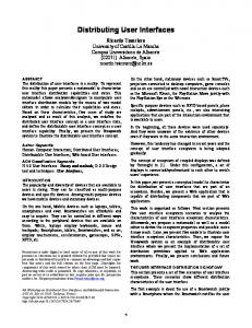
1.1 Motivation: the bridge between organizations and Information Systems Today Information Systems (ISs) are a fundamental part of most modern organizations. Nevertheless, they do not have necessarily the impact on carrying out interactive and non-interactive tasks of these organizations. There are many causes for this lack of exploitation. On the one hand, organizations were created without thinking about technology that is available nowadays, until now, the golden rule was: “First Organize then Computerize” [vand02]. On the other hand, some ISs have been created without considering the users and the organizations in which these users are operating. This lack of coordination between the organization evolution and the development of ISs has generated a rupture on the connection bridge and a potential breakdown in their usage. Figure 1 shows unidirectional arrows depicting how the information passes from the software industry to the organizations and vice versa. There is no direct connection channel. So, the organizations do not get what they expect from a software, and software developers sometimes fail to fill the expected results because they do not have any understandable communication channel to identify organizations’ requirements properly.
9
1. Introduction
Organizational connection requirements
Technological connection
Organization
Hybrid connection Figure 1-1 Misunderstanding in the communication link between IS and Organizations
Understanding work is crucial for building successful information systems, which are systems which clearly address business and user requirements. First, an IS, to be understandable in the organization, must take current work practices into account. Second, because an IS, to a certain degree, determines both what work can be done and how the work can be performed. For this purpose, it must be designed according to the organizations objectives and goals [Trae99]. The application of workflow management technology in the organization consists of a possible attempt to address the aforementioned shortcomings: it has been widely studied in a number of research projects such as: control applications [zurM02; Mano02], workflow patterns [Russ04; vand03]. The Workflow, a term coined in the 70`s, is referring to the handling of businesses processes using information systems, and denominates the automation of a business process, in whole or part [WfMC97]. The existing approaches can be grouped into three categories: (1) the application of workflow concepts to data warehouse design and operation, (2) the analysis of technical facilities for audit trail generation, and (3) the analysis of workflow audit trail data from an enterprise controlling perspective [zurM02]. Workflow patterns for human resources and for routing workflow components [vand03] are helpful to model workflow, however, there is still no advance in the modeling of the managerial activities. The development of workflow systems progressively represents major new challenges, apart from the above mentioned, we summarize them as follows: 1) Lack of integration of individual interactive systems in the global workflow. Often, individual users in organizations already have their own software to use to carry out their interactive tasks, as they have been assigned. This is not problematic. But when the time comes to communicate the results of their tasks to their hierarchy or to their colleagues, apart from using traditional e-mail, they do not rely on dedicated software for supporting the communication. 2) Lack of system integration both at a local and at a global scale. Small-scaled and large-scaled organizations usually experience some trouble not in defining and assigning the tasks to the individual workers, but in integrating them in a complete workflow which could be reinforced by a system. Indeed, if a workflow is implemented manually, it is more complicated to respect the constraints imposed by this workflow as the workers could fell free to respect or not to respect the rules. 10
1. Introduction
3) Activities changes induced by inappropriate technological integration. It is too often heard that people in organizations are forced to change their organizational structure and work process because of the setup of a new workflow system, as opposed to the tailoring of such as system to the already existing workflow. Of course, installing a new computer-based workflow inevitably changes the procedures, but should be limited. 4) Difficulty of obtaining a workflow system evolving with the organization. When the organizational structure changes, but the workflow does not change, it is complicated to reassign the tasks if a logical workflow has not been defined independently of the organizational structure. The consequence is that the software used for supporting individual or collective tasks need to be reassigned. It is likely that a workflow sustaining an organization cannot be updated instantly each time the organization is evolving, but if at least some support for considering evolution is provided, the impact of the required changes could be minimized. 5) Absence of considering real group requirements in workflows. Typically, a workflow often represents a tiling of existing software with people trying to coordinate their work among themselves by relying on implicit (e.g., manual, verbal, informal) communication schemes. Therefore, real group requirements should be considered. For instance, one could consider addressing Mandviwalla & Olfman [Mand94] criteria for support group interactions, such as the following ones we selected in our work: o “Support carrying out group tasks” from the individual level continuously throughout the global level: individual, within groups, for the group as a whole, among groups, within organization, and among organizations. o “Support multiple ways to support a group task”: in principle, there should not be unique way to carry out a single group task, but several mechanisms should be offered for this purpose. If a mechanism is no longer available, another one should be selectable. o “Support the group evolution over time”: when the group evolves over time, the workflow definition should be easily maintained and reflected in the system. The proposal for this project is to re-establish one part of the connection link between organizations and IS with a workflow information system, as depicted in Figure. 1-1 with the hybrid connection. In order to bridge this gap, we need to investigate the issues posed by integrating the activities related to the two gulfs of this bridge: organization management and software development. As we are mainly interested by the users’ concerns, a special focus will be placed on the User Interface (UI).
11
1. Introduction
1.2 Some issues 1.2.1
About Information Systems
An Information system (IS) is hereby defined as “a set of interrelated components that collect (or retrieve), process, store, and distribute information” [Laud06]. Information related IS typically is stored in databases. Today, the importance of IS, in nearly all companies and organizations, is fundamental. Different types of ISs can be distinguished depending on the operational level they serve in the organization (i.e., strategic, management or operational level) or their major functional area (e.g., sales and marketing, manufacturing and production, finance and accounting, and human resources). An IS constitutes a construction: • • • •
Of information that forms a partial representation of properties of the organization; Of treatments that manipulate those systems in view of taking care of the goals associated those activities of the organization; Of management rules that govern the execution of those treatments; Of human resources and technologies where synergic is useful to the operation of information systems.
Management Information Systems is a general name for the academic discipline covering the application of information technology to business problems. The area of study should not be confused with computer science which is more theoretical in nature and deals mainly with software creation, and neither with computer engineering, which focuses more on the design of computer hardware. Workflow Management (WfM) is a fast evolving technology which is increasingly being exploited by businesses in a variety of industries. Its primary characteristic is the automation of processes involving combinations of human and machine-based activities, particularly those involving interaction with information technology (IT) applications and tools. A Workflow Management System (WfMS) is a system that defines, creates and manages the execution of workflows through the use of software, running on one or more workflow engines, which is able to interpret the process definition, interact with workflow participants and, where required, invoke the use of IT tools and applications [WfMC97]. 1.2.2
Comparison between Workflow and Task model
When an interactive system is developed for a single user, user-centered design typically involves techniques for capturing user’s requirements: the task model is a representative example among others. When a workflow is designed, it should typically consider aspects related to the organization, the members of this organization, and the description of their daily work, which is usually done through workflow modeling. Therefore, workflow and task modeling is in some way correlated. The workflow describes processes but each process is composed of a series of tasks. Due to the great 12
1. Introduction
quantity of research that has been conducted regarding both approaches, we will describe the differences and the edges between the workflow and task models. Briefly, we can say that workflow models describe the flow of work in between and within organizations, and task models define the possible actions available for a user to accomplish a goal. Marshak [Mars97] identified four dimensions for describing work: the action structure, the actors, the tools and the information. Actions are steps required to make the necessary changes to accomplish a goal. Actors perform work by carrying out their choice of actions. Tools are the resources that are used by the actors to complete the actions. The information that is acted on is represented by objects; objects are also used to modeling useful contextual information used in actions. These four dimensions for describing workflow have natural correspondences in the task modeling domain [Trae99]. However, task models were not specifically designed to ensure flexibility in automating business processes, also workflow models are useful for group or organization interaction, while task models focus on individual users as opposed to collaborative (more than one user working in the same task at the same time) or cooperative (more than one user working in the same task at different time) tasks involving multiple users. Both concepts not necessarily require being in the same physical space. Workflow systems inherently focus on the management of task accomplishment process. Many of the components that are commonly included in workflow models are not found in task models. According with Manolescu [Mano02], these components include process monitor, history, persistence, manual intervention, work list, and federated workflow. Our examination of theses models has resulted in a more substantial differentiation; task models just considered the definition of one task to one user. As a consequence there is a limitation to model business processes. More than this, currently modeling workflow involves the definition of multiple users for one task. However, to model the organization and their processes, we need to consider: one task for one user, one task for several users, many tasks for one user, and many tasks for several users.
1.3 Epistemology of the research The epistemological reflection of a research concerns to an investigator who tries to carry out a rigorous investigation, and then it allows assuring the validity and legitimacy its investigation. The epistemological reflection must lead the investigator to understand the set of the preconceptions on which their investigation is based. In the foundation of a scientific work a reflection of the assumptions made and the clarity of the argumentation
13
1. Introduction
are the most critical requirement. These assumptions deal with the question whether a reality exists independent of an observer (objective view), which implies that the spatiotemporal objects contained in such a reality can be observed independent of the individual observer. The opposite, the subjective view, indicates that reality studied is described based on the observer and multiple views can be generated of the same reality. In order to do an epistemological reflection of this research; we will try to answer two questions: whether the elements contained in the universe of discourse are based on the existence of an objective reality (ontological question) and whether this objective reality can be perceived in a subject-independent way (epistemological question). The answer to the epistemological question determines whether the concepts presented in this work can be verified on a subject-independent basis, whereas the answer to the ontological question determines whether the truthfulness of the concepts presented can be determined objectively by comparing them to real world objects, [zurM02]. For both the ontological as well as the epistemological question, idealistic and realistic positions can be distinguished. While an ontological realist accepts the notion of an objective reality (i.e. objects exist regardless of their recognition by an observer), the ontological idealist (or metaphysical anti-realist) refutes such a concept. Similarly, while an epistemological realist claims that reality can be observed as such and therefore objective knowledge is possible, the epistemological idealist denies this idea and states instead that knowledge always depends on the observing mind. These views lead to three different positions, as depicted in Table 1-1 (the combination of ontological idealism with epistemological realism is not possible, since it is impossible to claim a mind-independent observation of a world-in-itself, if the existence of this world-in-itself is refuted). Ontological realist metaphysical realist
or Ontological idealist or metaphysical anti-realist
Epistemological realist
A real world exists; it can Not possible. be observed independent of the mind of the observer.
Epistemological idealist
A real world exists; it cannot be observed independent of the mind of the observer.
A real world does not exist; thus all observations depend on the mind of the observer.
Table 1-1 Fundamental Ontological and Epistemological Positions. [zurM02].
14
1. Introduction
Based on these fundamental positions, the philosophy of science has developed several partially conflicting – positions. The main philosophical positions for scientific work in the area of information systems are critical rationalism1, and constructivism. The positioning that applies to the statements of this work is a constructivism with regard to the understanding of reality and the way how theories are developed and communicated, as constructivist world view leads to subject-dependent cognitions that cannot be verified or falsified against an outside reality. Due to the unknowability of reality, an empirical verification of theoretical concepts is impossible. Von Glasersfeld, [vonG84], replaces the concept of verifiability with the notion of viability: “To the constructivist, concepts, models, theories, and so on are viable if they prove adequate in the contexts in which they were created”. In order not to arrive at an absolute relativism, where every model constructed is as valid as any other model, criteria are necessary to select a “fitting” model over other, competing models. Two distinct approaches to arrive at a valuation of constructivist theories are coherence and consensus. On an individual basis, coherence describes the agreement between different cognitive patterns within one subject’s brain, while consensus describes the agreement between the cognitive patterns of several subjects. In order to communicate constructivist theories or concepts among several subjects, a concept developed by one subject has to be reconstructed or comprehended by the other subjects. The inter-subjective communication of theoretical concepts is one of the main work areas of the methodical constructivist movement2. The movement is based on the notion of language critique, which seeks the development of an inter-subjective scientific language that serves as the basis of scientific discourse. Therefore the focus of methodical constructivism is the development of a viable procedure to construct scientific knowledge and to communicate this knowledge among peers.
1.3.1
Reflections of the research.
Based on the statements above, the positioning of this work is as follows: Regarding the recognizability of real world phenomena, we follow a constructivist approach. This follows from the fact that a business process is a logical ordering of activities. Thus it is a theoretical construct that by nature cannot be observed in the real world. From a critical rationalist view, business processes could be observed as the sum of their instantiations. Since all that can be observed are the individual actions of process partici1
The critical rationalism, found predominantly in the works of Popper and Albert, is based on an idealistic ontological view (i.e., there exists a world-in-itself). Theories can be measured against this real world, but, as a Popper points out, it is impossible to prove a theory, but it is possible to disprove it through falsification. 2 Founded on the works of Erlangen School of philosophy by Kamlah and Lorenzen.
15
1. Introduction
pants, the process as a whole has to be constructed by the observer through abstraction and generalization. It should be noted that we do not refute the existence of a world-initself (i.e., a reality), but whether this reality exists or not does not have an impact on the concepts discussed in this work. Similarly, for the process of modeling and theory-building, a methodical constructivist approach is followed, and the reasons for this choice are:
An objective perception of a subject-independent reality is impossible. Observations, deductions, inductions and subsequent statements are based on a subject-dependent construction of reality. Therefore, a validation of the statements given in this work against an objective reality is not possible. Instead, the viability of the statements can be tested by judging their “fit” into the constructed reality.
The subjects of this work are organizational processes and the opportunities to manage and control them with the help of an information system is challenging. An organizational process is a conceptual entity. Unlike a material object a process has no physical manifestation, other than (in some instances) the output of the process. Therefore, the representation of a process in terms of a (formal) model is a theoretical construct, whose features cannot be tested or validated against the features of objectively perceivable “real world” entities.
Different interpretations may appear depending on the contexts of use. Due to the nature of constructivist perception, the same environmental situation can be observed and interpreted differently by different subjects. In the context of process controlling, this means that given the same values of the same set of parameters, different subjects may arrive at different conclusions.
The problem of inter-subjectivity may be obvious with regard to linguistic terms and expressions, but not necessarily outside. In order to achieve a similar understanding of the meaning of the basic terms, an initial discourse is necessary. This discourse does not need to be complete and exact, but it has to fit the situation in order to avoid an overly complex formal procedure.
The development of a terminological foundation is especially important as this work is positioned at the junction of enterprise controlling and information system design. In order to create models and theories that are meaningful for both domains, a common understanding of central terms has to be established, and potential homonym- and synonym- conflicts have to be eliminated.
16
1. Introduction
1.4 Thesis statement From a User Interface (UI) standpoint, there exists today a gap between the development life cycle of user interfaces for individual tasks and the development life cycle of the complete workflow. As a consequence, we have adopted the following research question: Would it be possible to generate the user interface of a workflow information system from its specifications (provided that they address the relevant aspects) and the different constructs that link the tasks and the users together? We argue that with a fundamental point of view, this could be achieved by reviewing some selected work, introducing the modeling concepts supporting this, defining an extension of a User Interface Description Language (UIDL) to express these concepts in an integrated way, transferring them in a software system that supports defining the workflow and generates the corresponding code. It is possible to create a methodology for developing the user interface of a Workflow system that is explicitly based on the organization requirements. It is assumed that the various elements of the workflow of concern already exist: user, resources, task, process, and workflow. Once these elements exist, the method could be applied. It is not the purpose of the method to design or test a workflow under construction. Therefore, we will defend the following thesis:
In order to bring together the advance of the Information System and the workflow modeling in a co-evolutionary way, it is possible to introduce a conceptual model of the workflow information system so as to derive a potential user interface as systematically as possible.
1.5 Reading Map The remainder of this thesis is structured as follows: Chapter 2 presents current methods, models and tools to describe the task model, workflow, and User Interface description languages. They are compared and assessed using a set of criteria. The criteria will help us to evaluate the usefulness of the method and tools proposed in this thesis and will validate the choices that we will do regarding the models considered in the next chapter.
17
1. Introduction
Chapter 3 defines the models and the language chosen to represent these concepts (the user interface description language UsiXML). Chapter 4 presents the methodology to generate the User Interface from the models described in chapter 3. Chapter 5 illustrates the methodology proposed through one reasonably scaled case study. Chapter 6 will contain elements of validation, both from an internal point of view (theoretical) and from an external point of view (empirical). Chapter 7 will conclude by summarizing our contributions and exploring some avenues for future work.
18
2. State of the Art
Chapter 2 State of the Art This chapter starts by presenting a theoretical framework for workflow, workflow patterns (Section 2.1), task models (Section 2.2), model-based, context-sensitive user interfaces (Section 2.3), and existing User Interface Description Languages which could support parts or whole of their specification (Section 2.4). This framework then serves as a reference for structuring our description of current methods and tools for developing user interfaces for multiple platforms. These tools and methods are then analyzed and compared using a set of quality criteria. We also look at model-based approaches for specifying user interfaces.
2.1 Workflow modeling The organizations are forcing to increasingly integrate and automate their business processes; a common term used to automate the processes and have a control of these, is workflow. The Workflow Management Coalition [WfMC99] defines it like “the automation of a business process, in whole or part, during which documents, information or tasks are passed from one participant to another for action, according to a set of procedural rules”. According to [Mars94; Mars97], the essential workflow characteristics are: tasks/activities that are performed by (role-playing) persons, using supporting tools that give access to a variety of shared information resources. Some workflow concepts that are common in many systems have been identified by Manolescu [Mano02]: 1) Monitoring for contributing information about the circumstances of workflow during execution. 2) History of workflow actions for evaluation or recovery. 3) Persistence to save the historic information and provide access to it. 4) Manual Intervention for changing the order that activities are performed in as they are performed. 5) Worklist to coordinate the activities among the workers. 6) Federated Workflow to address the issue of how workflow systems interoperate. Workflow technologies facilitate modeling, redesigning and administration of process in an organization [Eich04]. Due to the importance of workflow nowadays, several models
19
2. State of the Art
have been proposed to design and specify it. In addition, workflow patterns have been identified to enriched this specification by introducing resources representation (i.e. workflow resources patterns) [Russ05], and for routing workflow constructions (i.e. workflow patterns) [vand03].
2.1.1 Notation In this section we will introduce the most widely workflow notation descriptions, Statechart Diagrams and Petri Nets. A statechart diagram is a graph that represents a state machine describing the response, of an object of a certain class, to the receipt of outside stimuli. Petri Nets are a tool for modeling and analyzing processes. One of their strengths is the capability to describe processes graphically. Accordingly with [vand02] the use of Petri Nets has a number of major advantages as: (1) ambiguities and contradictions are prevented; (2) the formalism can be used to argue about process; (3) it thus becomes possible to establish certain patterns. We will evaluate the characteristics of each model to identify the most suitable to represent workflow models. 2.1.1.a Petri Nets The concept of Petri net has its origin in Carl Adam Petri’s dissertation submitted in 1962. Petri nets are graphical and mathematical modeling tools applicable to many systems. As a graphical tool, Petri nets can be used as a visual-communication aid similarly as flow charts, block diagrams, and networks. Tokens are used through the nets to simulate the dynamic and concurrent activities of systems. As a mathematical tool, it is possible to set up state equations, algebraic equations, and other mathematical models governing the behavior of systems [Mura89]. The classical Petri net is a directed bipartite graph with two node types called places and transitions [vand98]. The nodes are connected via directed arcs. Connections between two nodes of the same type are not allowed. The classical Petri net allows the modeling of states, events, conditions, synchronization, parallelism, choice, and iteration. It does not allow the modeling of data and time. To solve these problems, many extensions have been proposed. Three well-known extensions of the basic Petri net model are: (1) the extension with color to model data, (2) the extension with time, and (3) the extension with hierarchy to structure large models. A Petri net extended with color, time, and hierarchy is called a high-level Petri net. 1. Extension with color. Tokens often represent objects (cases) in the system. If we want to represent attributes that are not easily represented by a token in a classical Petri net, the net model is extended with color. In a colored Petri net each token has a value often referred to as ‘color’. Transitions determine the values of the produced tokens on the basis of the values of the consumed tokens, i.e., a transition describes the relation between the values of the ‘input tokens’ and the 20
2. State of the Art
values of the ‘output tokens’. It is also possible to specify ‘preconditions’ for the transitions, which take the colors of tokens to be consumed into account. 2. Extension with time. For real systems it is often important to describe the temporal behavior of the system. Since the classical net is not capable of handling quantitative time, a timing concept is added. There are many ways to introduce time into the Petri net. Time can be associated to tokens, places, and/or transitions. 3. Extension with hierarchy. In order to avoid the tendency to large and complex specifications for real systems, a hierarchy construct, called subnet is provided. A subnet is an aggregate of a number of places, transitions, and subsystems. These hierarchies can be used to structure large processes. In the first level a simple description of the process is given, and at the next levels another more detailed behaviors are given. Notation Transition
Arc Token
Place
Definition Graphical representation Transitions are the active components of a Petri net. The triggering of a transition results in the state of the network being changed. Places and transitions can be linked by means of a directed arc. The state of a Petri net is determined by the distribution of tokens amongst the places. Places are the passive components of a Petri net. A place may contain no, one or more tokens.
yr
red
yellow
rg
gy
green
Figure 2-1. A set of traffic lights illustrated on a Petri Net. Source [vand02].
21
2. State of the Art
According with van der Aalst [vand98] modeling a workflow process definition in terms of a Petri net is rather straightforward: tasks are modeled by transitions, conditions are modeled by places, and cases are modeled by tokens. In the process dimension, building blocks such as the AND-split, AND-join, OR-split, OR-join are used to model sequential, conditional, parallel and iterative routing. 2.1.1.b Statechart Diagrams Harel statecharts (developed in 1987 by David Harel) are gaining some more general usage since a variant has become part of the Unified Modeling Language (UML). As it allow to model super states where activities can be part of a state. Classic state diagrams are so called "or diagrams”, because the machine can only be in one state or the other. With Harel statecharts it is possible to model "and machines”, where a machine is in two or more states at the same time. This is due to the possibility of having super states. Statechart diagrams are used to document the various modes (“state”) that a class can go through, and the events that cause a state transition. The (UML) state diagram is essentially a state diagram with standardized notation that can describe a lot of things, from computer programs to business processes.
Notation State
Transition
Initial State
Final State
Definition Graphical representation A state marks a mode of the entity. The State name graphical representation is by using a rectangle with rounded corners and the name of the state. A transition marks the changing of the object state, caused by an event. The repTransition resentation is by an arrow with the Even Name. The initial state is the state of an object before any transitions; it is marked using a solid circle. Only one initial state is allowed on a diagram. The final states mark the destruction of the object whose state we are modeling. The final state is drawn using a solid circle with a surrounding circle.
If an event E occurs in a state S and a condition C holds then make the transition to state T.
22
2. State of the Art
E(C)
S
T
Figure 2-2 A simple state machine
It is possible to have complex states [W3C05], namely one that has substates. S1
Initial
S11
S12
Figure 2-3 A state with sequential substates
In this case, S1 has sequential substates; when a state machine is in a state with such substates, it must also be in one and only one of the substates. The substates has a kind of “or” semantics and can be thought of as representing a decomposition of the parent state. In addition, Harel Statecharts provide concurrent substates, which represent a form of “and” logic. When a state machine is in a state with concurrent substates it must be simultaneously in each of the concurrent child states. The concurrent child states operate independently until they all terminate at which point the parent state also terminates.
23
2. State of the Art
S1 Initial
S11
S12
Initial
[S121]
-------------
S111
[S122]
-------------
S112
[S123]
Figure 2-4 A combination of concurrent and sequential substates
Also is possible to represent the concepts of parallel states, which can be coordinated by means of join and synchronization states.
[S1] S11
S12
S13
-------------------------------[S2] S21
S22
S23
Figure 2-5 Parallel states to be coordinated
The Harel semantics for transitions is based on the notion of an underlying event queue. If there is an event in the queue, it is processed according to the given state configuration, and a transition may be triggered. The transition is triggered and all associated actions are executed before the next event in the queue is examined. Here is a simple example State Diagram that models that status of a user’s account in a Bug Tracker system:
24
2. State of the Art Approve User
Create User
Active
Pending Deactive User
Active User
Deactive
Delete User
Reject User
Figure 2-6 An example of state diagram
2.1.2 Workflow Languages Workflow languages represent complex scenarios and can describe the logical presentation. They capture their structure, dynamics and states. Workflow languages are tools that can be used to model a workflow and to execute it.
2.1.2.a Yet Another Workflow Language (YAWL). Yet Another Workflow Language (YAWL) is a workflow language based on Petri nets. It has been extended with features to facilitate patterns involving multiple instances, advanced synchronization patterns, and cancellation patterns [vand05]. A workflow specification in YAWL is a set of processes definitions that form a hierarchy. Tasks are either atomic task or composed ones. The lower level in the hierarchy refers to a process definition. Atomic tasks form the leaves of the graph structure. Each process definition consists of tasks and conditions which can be interpreted as places. Each process definition has one unique input condition and one unique output condition. In YAWL they map each view of a Web application to a YAWL’s activity (atomic task). The view then becomes a task assigned to the user; user interaction with the view becomes the accomplishment of the task. Once task has been executed the workflow progress. YAWL supports the so called data perspective. It is possible to define data elements and use them for conditional routing, for the creation of multiple instances, for exchanging information with the environment, etc. However, until today, the data perspective is not supported by the YAWL editor. They decided for a simplified solution in which they use a set of name-value associations to represent presentation data and they express conditions as simple predicates on this set.
25
2. State of the Art
2.1.2.b Exchangeable Routing Language (XRL) XRL is a workflow language that uses XML for the representation of process definitions and Petri nets for its semantics. Since XRL is instance-based, workflow definitions can be changed on the fly and sent across organizational boundaries. These features are vital for today's dynamic and networked economy. The project team has developed a workflow management system, named XRL/flower, to support XRL. XRL/flower benefits from the fact that it is based on both XML and Petri nets [Verb02]. An XRL route is a consistent XML document, that is, a well-formed and valid XML file with top element route. The structure of any XML document forms a tree. In case of XRL, the root element of that tree is the route. This route contains exactly one so-called routing element. A routing element (RE) is an important building block of XRL. It can either be simple (no child routing elements) or complex (one or more child routing elements). A complex routing element specifies whether, when and in which order the child routing elements are done. XRL is presented in a paper by W.M.P. van der Aalst and A. Kumar [vand00]. The paper concludes: "The semantics of XRL was expressed in terms Petri nets by providing a direct mapping from each routing element to a Petri net construction. Thus, any workflow can be expressed in XRL and then translated into a Petri net representation, which lends itself easily to analysis”.
2.1.3 Tools To manage the workflow, many academic and industrial research projects have been developed. The capabilities of these products are being enhanced in significant ways. 2.1.3.a The Progression Model The Progression model [Stav04] has incorporated some of the managing concepts of workflow to increase the flexibility in IS. It makes explicitly the steps and transactions as user undertakes when using an IS. As the user progresses towards accomplishing a task or goal, the progression model infrastructure records each step and the state of the transaction and workflow. A progression is a workflow transaction and a sequence of scenes in a process to create a workflow transaction. The progression model is displayed to the user in the single progression section through four main panels. USER INTERFACE – this panel displays the widgets or interface elements that are specified in the user interface element of the markup document for the current scene. TRANSACTION – This panel display all the transaction items of the progression as specified in the workflow transaction element of the markup document, including the information that the user has entered up to that point in the progression. WORKFLOW – This panel display the status information for the progression as specified in the workflow element of the markup document. The workflow status shows the scenes of the progression in the recommended order. Each scene is associated with a name, the worker assigned to complete
26
2. State of the Art
it, and the current status of its completion; these are all displayed in a table format. FEEDBACK – This panel consists of constraints, information status, and markup document. The constraints sub-panel display any information related to constraints that are violated throughout the progression. The information status sub-panel display the information that is missing and required to complete the transaction. The markup document sub-panel displays the current state of the markup document. The single section also has buttons to start a new progression, open an existing progression, save the current progression, and quit the progression analyzer.
Figure 2-7 The progressing analyzing displaying the Enter Name scene
27
2. State of the Art
Figure 2-8 A screenshot of a more complex user interface and progression model in the Progression Analyzer
2.1.3.b Microsoft Windows Workflow Foundation Microsoft Windows Workflow Foundation (WWF) [Espo05] is an extensible framework for developing workflow solutions on the Windows platform. It provides a single, unified model to create end-to-end solutions that span categories of applications, including human workflow and system workflow. WWF supports two fundamental workflow styles: sequential workflow and state machine workflow. A sequential workflow is useful for operations expressed by a pipeline if steps that execute one after the next until the last activity completes. Sequential workflows are not purely sequential in their execution, they can still receive external events or start parallel tasks, in which case the exact sequence of execution can vary somewhat. A state machine workflow is made up of a set of states, transitions and actions. One state is denoted as a start state, and then based on an event a transition can be made to another state. The state machine workflow can have a final state that determines the end of the workflow.
28
2. State of the Art
Figure 2-9 The Visual Studio 2005 workflow designer. Source http://msdn.microsoft.com/library/default.asp?url=/library/enus/dnlong/html/WFGetStart.asp
Figure 2-10 Building blocks of a WWF workflow. Source http://msdn.microsoft.com/library/default.asp?url=/library/enus/dnlong/html/WFGetStart.asp
29
2. State of the Art
Figure 2-11 An interior view of the OrderCreatedEvent EventDriven activity. Source http://msdn.microsoft.com/library/default.asp?url=/library/enus/dnlong/html/WFGetStart.asp
2.1.3.c Flexo Engine The Flexo Engine [Dena] is a Workflow Management System based on a Petri Network formalism for process description. It interprets the workflow description, controls the instantiation of processes, sequences activities, adds work items to the user work lists and invokes application tools when necessary. Flexo can implement monitoring screens allowing authorized users to track Key Performance Indicator (KPI) evolution in time. Flexo Engine is a generic toolset that can be used in various contexts such as: (1) Call centers. Flexo dynamisms call centers by linking telephone and Internet channels. When a customer could not find his way through the online procedure, he contacts the call centre where an operator picks up his file and resumes it, exactly from the point where he stopped on the Internet. (2) Thin layer above business critical applications. Flexo valorizes your IT investments by connecting isolated applications through a simplified and specific interface. (3) Service Oriented Architecture. Flexo can use the XML standard BPEL4WS to orchestrate the interactions between Web Services associated with previously isolated services or remote commercial partners.
30
2. State of the Art
Figure 2-12 Define Operations & GUIs. Source http://www.denali.be/MimeObjects/SharedContento/1000001/domsnyersslidesemjune30_10083 94.pdf
Figure 2-13 The workflow modeler. Source http://www.denali.be
31
2. State of the Art
2.1.3.d WebSphere® MQ Workflow WebSphere® MQ Workflow [IBM] supports long-running business process workflows as they interact with systems and people. Automates and tracks business processes in accordance with business design. Provides integration processes with rich support for human interactions. Enables use with WebSphere Business Integration Modeler and Monitor for design, analysis, simulation and monitoring of process improvements. Buildtime is the graphical process definition tool that is part of the WebSphere® MQ Workflow product. You can graphically define business processes and their activities to the level of detail needed for automation. Buildtime includes graphical support for declaring and documenting: 1) business rules on process navigation between steps, 2) business rules for role-based work assignment, 3) process interface definitions (data, programs, queues). 2.1.3.e Arena Basic Edition Arena Basic Edition software [Rock00] brings the power of modeling and simulation of business process. The advantages that offers this software is that is capable to simulate the current “as-is” business environment with an unlimited realm of possible “to-be” configurations [Rock00]. Arena has been widely used to model problems involving: manufacturing, supply chain, military/defense, health care, contact centers and business process. In [Rock00] the traditional uses of Arena are described as follows: • • • •
Model processes to define, document, and communicate. Simulate the future performance of business to understand complex relationships and identify opportunities for improvement. Visualize operations with dynamic animation graphics. Analyze how your system will perform in its “as-is”. Configuration and under a myriad of possible “to-be” alternatives so that you can confidently choose the best way to run your business.
Arena based its model in flowcharts. The word itself suggests two of the main concepts behind modeling and simulation. The flowchart is conceived as the process map or model that describes a flow. The flowchart components used in Arena are modules, which are the flowchart and data objects that define the process to be simulated, [Rock00]. All information required to simulate a process is stored in modules, the Basic Module’s Processes are: • • • • •
Create: The start of process flow. Entities enter the simulation here. Dispose: The end of process flow. Entities are removed from the simulation here. Process: An activity, usually performed by one or more resources and requiring some time to complete. Decide: A branch in process flow. Only one branch is taken. Batch: Collect a number of entities before they can continue processing. 32
2. State of the Art
• • • • •
•
•
•
•
Separate: Duplicate entities for concurrent or parallel processing, or separating a previously established batch of entities. Assign: Change the value of some parameter (during the simulation), such as the entity's type or a model variable. Record: Collect a statistic, such as an entity count or cycle time. Entity. Entities are the items, customers, documents, parts, that are being served, produced. Queue. This data module serves to change the ranking rule for a specified queue. The default ranking rule for all queues is First In, First Out unless otherwise specified in this module. Resource. This data module defines the resources in the simulation system, including costing information and resource availability. Resources may have a fixed capacity that does not vary over the simulation run or may operate based on a schedule. Schedule. This data module is used in conjunction with the Resource module to define an operating schedule for a resource or with the Create module to define an arrival schedule. Additionally, a schedule may be used and referenced to factor time delays based on the simulation time. Set. This data module defines various types of sets, including resource, counter, tally, entity type, and entity picture. Resource sets can be used in the Process module. Counter and Tally sets can be used in the Record module. Variable. This data module is used to define a variable’s dimension and initial value(s). Variables can be referenced in other modules (e.g., the Decide module), can be reassigned a new value with the Assign module, and can be used in any expression.
In arena it is possible to represent with images: entities, resources, and global pictures. The software contains libraries for any of these three types of picture animation. Also, it provides an editor to draw any image starting from scratch or reusing previous predefined images. Animation also can be of great benefit in enticing others in the organization to be interested in process improvement [Rock00]. A screenshot of Arena is shown in Fig. 2-14.
33
2. State of the Art
Figure 2-14 Screenshot of the Arena Flowchart Editor
In the screenshot above it is possible to identify the icons used for the different modules used to build the models. Similarly the vans and desks on the left represent the resources available to handle the process. Another interesting capability of this software is its interaction with Microsoft Visio. The Arena Basic Edition includes a built-in interface to Visio, mapping shapes from a Visio drawing to the appropriate simulation constructs in Arena. Process hierarchy is captured in the Arena simulation model, including activity-based costing and process logic, enabling an understanding of the distribution of cost and effort among process components [Rock00]. Arena it’s a good option to model the static part of the workflow model, how it looks actually the enterprise. The model then can be exported in access 97, with the export plugin provided by the software, from which it could be possible to use this information to define a first version of the potential user interface. This first draw of the UI could be then enriched with the elements that arena not consider that are relevant for the workflow itself. For instance, task assignment or workflow patterns.
34
2. State of the Art
2.1.3.f
Colored Petri Net Tools
Colored Petri Net (CPN) Tools [CPNT06] is a software tool for editing, simulating and analyzing Colored Petri Nets. The GUI is based on advanced interaction techniques, such as tool glasses, marking menus, and bi-manual interaction [CPNT03]. Feedback facilities provide contextual error messages and indicate dependency relationships between net elements. A fast simulator efficiently handles both untimed and timed nets. The CPN Tools editor, described in [CPNT06], has the following characteristics: Each of the cursors is controlled with its own separate input device, such as a mouse, a pen, or a trackball. Multiple cursors can be controlled by one or more users at the same time. The index, that is located in the left side of the CPN Tools window, contains: •
Tool box: A list of all the tools available in CPN Tools. Tools for creating new CP-net elements, simulating nets, changing line colors and line widths, etc., are accessible from tool palettes in the tool box in the index and through marking menus on the various objects in the workspace.
Figure 2-15 Screenshot of the CPN Tools Creating icons. Source [CPNT06]
• Help: Links to Help, Homepage, Report Bug and other WebPages. • Options: Various options for, e.g. simulation So as the list of the nets that is currently open in the tool. The index contains an entry for each net that is opened in the tool. A net entry contains: • History: the list of commands that have been performed on the net • Step: the number of steps that have executed in a simulation • Time: the current model time • Declarations: the declarations of color sets, functions, constant values, etc. All declarations are written in the CPN ML language. • Page entries for pages in the net. Bellow we show a CPN model that describes how two different kinds of processes are sharing three different kinds of resources. It is simple to understand and easy to simulate/modify [Jens97].
35
2. State of the Art
Figure 2-16 Screenshot of a Colored Petri net with resource allocation (Source [Jens97])
The above example, from [Jens97], shows a set of processes, which share a common pool of resources. There are two processes (p and q) and three resources (r, s, and t). The processes could be different computer programs (e.g., text editors and drawing programs) while the resources could be different facilities shared by the programs (e.g., tape drives, laser printers and plotters). Each process is cyclic and during the individual parts of its cycle, the process needs to have exclusive access to a varying amount of the resources. The different states that process could reach are five, depicted with the circles with the letters A-E, this notation corresponds to the places in the Petri net. Resources are traditionally stored in places, so three places (R-T) are used to handle with the three types of resources. Each token (shown next to each place with a number and a type, for instance A has 3 token of type q) that travel through the net must have information related to it (the color) that depends of its type. With the color information each place just groups
36
2. State of the Art
token that can be handled by it. In this example there are two kinds of tokens p and e (next to each place). The net is composed of conditions that connects places and allows the pass of token from one place to another. Transitions T1-T5 represents the shift from state to the next. The surrounding arc inscriptions tell us how resources are reserved and released. In [Jens97] T2 is exemplified. Transition T2 has three surrounding arcs. The arc expression “(x,i)” appears twice (on the input arc from B and on the output arc to C, while “case x of p=>2`e | q=>1`e” appears once (on the input arc from S). Together these three arc expressions have two variables, x and I (x has type U while i has type I). Intuitively, the three arc expressions tell us that an occurrence of T2 moves a token from B to C ± without changing the color (because the two arc expressions are identical).
2.1.4 Workflow patterns The concept of patterns was introduced by Christopher Alexander, who defined them in the architectural context. Alexander was the first one who proposed a format for documenting patterns and combined patterns into a pattern language. The pattern initiative was supported and resulted in a set of significant milestones, i.e. pattern languages, in other application fields and domains. As described in [Rieh96], a pattern is “the abstraction from a concrete form which keeps recurring in specific non-arbitrary contexts”. A workflow pattern is a specialized form of a design pattern. Workflow patterns refer specifically to recurrent problems and proven solutions related to the development of workflow applications in particular, and more broadly, process-oriented applications. Due to the large number of workflow products a group of researchers have identified a group of workflow patterns that provide the basis for an in-depth comparison of a number of commercially available workflow systems. Since these patterns are related to workflow they are presented in detail in this section. We selected the most relevant ones that will be used in Chapter 3 as part of the workflow model, further in Chapter 4 we will show how they would like graphically, using Petri nets descriptions. Our choice was based on: • Extensive coverage. We identified all the relevant concepts related to workflow modeling and found the correspondent patterns to represent them. They aim to capture the various ways in which resources, data and control are presented and utilized in workflows. • Adequacy. They fit to our needs to represent the workflow and map concepts from workflow patterns to the workflow model. • Level of detail. They describe all the details traditionally hided in workflow models. • An extensive consideration of multiple configurations. It allows us to describe the organization with multiple configurations and not a single one. 37
2. State of the Art
2.1.4.a Control-flow patterns In [Vand03] there are 20 patterns that identify useful routings construct. The basic control flow patterns closely match the definitions of elementary control flow concepts provided by the Workflow Management Coalition. Pattern 1) Sequence
Description An activity in a workflow process is enabled after the completion of another activity in the same process.
2) Parallel Split
A point in the workflow process where a single thread of control splits into multiple threads of control which can be executed in parallel, thus allowing activities to be executed simultaneously or in any order.
3) Synchronization
A point in the workflow process where multiple parallel subprocesses/activities converge into one single thread of control, thus synchronizing multiple threads (each incoming branch of a synchronizer is
4) Exclusive Choice
5) Simple Merge
executed only once). A point in the workflow process where, based on a decision or workflow control data, one of several branches is chosen A point in the workflow process where two or more alternative branches come together without synchronization (none of the alternative branches is ever executed in parallel). Table 2-1 Basic control-flow patterns
The advanced branching and synchronization patterns do not have straightforward support in workflow engines; nevertheless, they are quite common in real-life business scenarios.
38
2. State of the Art
Figure 2-17 Design patterns for the multi-choice. Source[vand03] Pattern
Description A point in the workflow process where, based on a decision or workflow control data, a number of branches are chosen. A point in the workflow process where multiple
6) Multi-choice
7) Synchronizing Merge
paths converge into one single thread. If more than one path is taken, synchronization of the active threads needs to take place. If only one path is taken, the alternative branches should reconverge without synchronization. 8) Multi-merge
A point in the workflow process where two or more branches reconverge without synchronization. If more than one branch gets activated, possibly concurrently, the activity following the merge is started for every activation of every incoming branch. The discriminator is a point in a workflow process that waits for one of the incoming branches to complete before activating the subsequent activity. From that moment on it waits for all remaining
9) Discriminator
branches to complete and “ignores” them. Table 2-2 Advanced branching and synchronization patterns
The structural patterns illustrate typical restrictions imposed on workflow specifications. Pattern
Description A point in the workflow process where one or more activities can be done repeatedly.
10) Arbitrary Cycles
39
2. State of the Art
11) Implicit Termination
A given subprocess should be terminated when there is nothing else to be done. There are no active activities in the workflow and no other activity can be made active (and at the same time the workflow is not in deadlock). Table 2-3 Structural patterns
The next patterns involve a phenomenon that the author refers to as multiple instances. When considering multiple instances there are two types of requirements. The first requirements have to do with the ability to launch multiple instances of an activity or a sub-process. The second requirement has to do with the ability to synchronize these instances and continue after all instances have been handled.
Pattern
Description
12) Multiple Instances Without Synchronization
Within the context of a single workflow instance multiple instances of an activity can be created, i.e., there is a facility to spawn off new threads of control. Each of these threads of control is independent of other threads and there is no need to synchronize them. For one process instance an activity is enabled multiple times. The number of instances of a given activity for a given process instance is known at de-
13) Multiple Instances With a Priori Design Time Knowledge
sign time. Once all instances are completed some other activity needs to be started. For one case an activity is enabled multiple times. The number of instances of a given activity for a given case varies and may depend on characteristics
14) Multiple Instances With a Priori Runtime Knowledge
of the case or availability of resources, but is known at some stage during runtime, before the instances of that activity have to be created. Once all instances are completed some other activity needs to be started. 15) Multiple Instances Without a Priori Runtime Knowledge
For one case an activity is enabled multiple times. The number of instances of a given activity for a given case is not known during design time, nor is it known at any stage during runtime, before the instances of that activity have to be created. Once all instances are completed some other activity needs to be started. The difference with Pattern 14 is that even while some of the instances are being executed already completed, new ones can be created.
40
2. State of the Art
Table 2-4 Patterns involving multiple instances
Moments of choice, such as supported by constructs as XOR-splits/OR-splits, in workflow management systems are typically of an explicit nature, i.e. they are based on data or they are captured through decision activities. This means that the choice is made a-priori, i.e. before the actual execution of the selected branch starts an internal choice is made. Sometimes this notion is not appropriate.
Figure 2-18 Illustrating the difference between implicit (workflow A) and explicit (workflow B) XOR-splits. Source[vand03] Pattern 16) Deferred Choice
17) Interleaved Parallel Routing
18) Milestone
Description A point in the workflow process where one of several branches is chosen. The choice is not made explicit but several alternatives are offered to the environment. However only one of the alternatives is executed. A set of activities is executed in an arbitrary order: Each activity in the set is executed, the order is decided at run-time, and no two activities are executed at the same moment. The enabling of an activity depends on the case being in a specific state, i.e., the activity is only enabled if a certain milestone has been reached which did not expire yet. Table 2-5 State-based patterns
The following patterns describe the construction of cancellation. PATTERN 19) Cancel Activity
DESCRIPTION An enabled activity is disabled, i.e., a thread waiting for the exe-
41
2. State of the Art
cution of an activity is removed. 20) Cancel Case
A workflow instance is removed completely (i.e., even if parts of the process are instantiated multiple times, all descendants are removed) Table 2-6 Cancellation patterns
2.1.4.b Workflow data patterns From a data perspective, there are a series of characteristics that occur repeatedly in different workflow modeling paradigms.[Russ04] describes a series of workflow data patterns that aim to capture the various ways in which data is represented and utilized in workflows. The data visibility is relating to extent and manner in which data elements can be viewed by various components of a workflow process. Pattern
2) Block Data
Description Data elements can be defined by tasks which are accessible only within the context of individual execution instances of that task. Block tasks (i.e. tasks which can be described in terms of a corre-
3) Scope Data
sponding sub-workflow) are able to define data elements which are accessible by each of the components of the corresponding subworkflow. Data elements can be defined which are accessible by a subset of the
1) Task Data
4) Multiple Instance Data
5) Case Data
6) Folder Data 7) Workflow Data
8) Environment Data
tasks in a case. Tasks which are able to execute multiple times within a single workflow case can define data elements which are specific to an individual execution instance. Data elements are supported which are specific to a process instance or case of a workflow. They can be accessed by all components of the workflow during the execution of the case. Data elements can be defined which are accessible by multiple cases on a selective basis. Data elements are supported which are accessible to all components in each and every case of the workflow and are within the control of the workflow system. Data elements which exist in the external operating environment are able to be accessed by components of the workflow during execution. Table 2-7 Data visibility patterns
42
2. State of the Art
The data interaction focusing on the manner in which data is communicated between active elements within a workflow. Pattern 9) Data Interaction - Task to Task
Description The ability to communicate data elements between one task instance and another within the same case.
10) Data Interaction - Block Task to Sub-Workflow Decomposition
The ability to pass data elements from a block task instance to the corresponding sub-workflow that defines its implementation.
11) Data Interaction - Sub-Workflow Decomposi-
The ability to pass data elements from the underly-
tion to Block Task
ing sub-workflow back to the corresponding block task instance.
12) Data Interaction - to Multiple Instance Task
The ability to pass data elements from a preceding task instance to a subsequent task which is able to support multiple execution instances. This may involve passing the data elements to all instances of the multiple instance task or distributing them on a selective basis.
13) Data Interaction - from Multiple Instance Task
The ability to pass data elements from a task which supports multiple execution instances to a subsequent task. The passing of data elements from one case of a workflow during its execution to another case that
14) Data Interaction - Case to Case
is executing concurrently. The ability of a task to initiate the passing of data elements to a resource or service in the operating environment.
15) Data Interaction - Task to Environment – Push -Oriented
16) Data Interaction - Environment to Task – Pull – Oriented
The ability of a workflow task to request data elements from resources or services in the operational environment.
17) Data Interaction - Environment to Task - Push
The ability for a workflow task to receive and utilize
- Oriented
data elements passed to it from services and resources in the operating environment on an unscheduled basis. The ability of a workflow task to receive and respond to requests for data elements from services
18) Data Interaction - Task to Environment – Pull Oriented
and resources in the operational environment. 19) Data Interaction - Case to Environment – Push -Oriented
The ability of a workflow case to initiate the passing of data elements to a resource or service in the op-
43
2. State of the Art
erational environment. 20) Data Interaction - Environment to Case – Pull Oriented
The ability of a workflow case to request data from services or resources in the operational environment.
21) Data Interaction - Environment to Case - Push - Oriented
The ability of a workflow case to accept data elements passed to it from services or resources in the operating environment.
22) Data Interaction - Case to Environment – Pull -
The ability of a workflow case to respond to re-
Oriented
quests for data elements from a service or resource in the operating environment.
23) Data Interaction -Workflow to Environment – Push - Oriented
The ability of a workflow engine to pass data elements to resources or services in the operational environment.
24) Data Interaction - Environment to Workflow Pull - Oriented
The ability of a workflow to request workflow-level data elements from external applications.
25) Data Interaction - Environment to Workflow Push - Oriented
The ability of services or resources in the operating environment to pass workflow-level data to a workflow process.
26) Data Interaction - Workflow to Environment – Pull - Oriented
The ability of a workflow engine to handle requests for workflow-level data from external applications.
Table 2-8 Data interaction patterns
The data transfer consider the means by which the actual transfer of data elements occurs between workflow components and describe the various mechanisms by which data elements can be passed across the interface of a workflow component. Pattern 27) Data Transfer by Value - Incoming
Description
28) Data Transfer by Value - Outgoing
The ability of a workflow component to receive incoming data elements by value relieving it from the need to have shared names or common address space with the component(s) from which it receives them. The ability of a workflow component to pass data ele-
29) Data Transfer - Copy In/Copy Out
ments to subsequent components as values relieving it from the need to have shared names or common address space with the component(s) to which it is passing them. The ability of a workflow component to copy the values
44
2. State of the Art
of a set of data elements into its address space at the
30)Data Transfer by Reference - Unlocked
commencement of execution and to copy their final values back at completion. The ability to communicate data elements between workflow components by utilizing a reference to the location of the data element in some mutually accessible
31) Data Transfer by Reference - With Lock
location. No concurrency restrictions apply to the shared data element. The ability to communicate data elements between workflow components by passing a reference to the location of the data element in some mutually accessible location. Concurrency restrictions are implied with the receiving component receiving the privilege of read-only or dedicated access to the data element. The ability to apply a transformation function to a data element prior to it being passed to a workflow compo-
32) Data Transformation - Input
nent. The ability to apply a transformation function to a data element immediately prior to it being passed out of a workflow component.
33) Data Transformation - Output
Table 2-9 Data transfer patterns
The data-based routing characterize the manner in which data elements can influence the operation of other aspects of the workflow, particularly the control flow perspectives. Pattern 34) Task Precondition - Data Existence
Description Data-based preconditions can be specified for tasks based on the presence of data elements at the time of execution. Data-based preconditions can be specified for tasks
35) Task Precondition - Data Value
based on the value of specific parameters at the time of execution. Data-based postconditions can be specified for tasks based on the existence of specific parameters at the time of execution.
36) Task Postcondition - Data Existence
37) Task Postcondition - Data Value
Data-based postconditions can be specified for tasks based on the value of specific parameters at the time of execution. The ability for an external event to initiate a task.
38) Event - based Task Trigger 39) Data - based Task Trigger
The ability to trigger a specific task when an expression based on workflow data elements evaluates to true. The ability to alter the control flow within a work-
40) Data - based Routing
45
2. State of the Art
flow case as a consequence of the value of databased expressions. Table 2-10 Data-based routing patterns
2.1.4.c Workflow resources patterns In an organization there are resources that can be human or non-human, although these patterns are focus on human resources. For [Russ05] a resource is an entity that is capable of doing work. A human resource has a specific position and privileges. In terms of the organizational hierarchy, each resource may have a number of specific relationships with the other resources. Non-human resources may be durable or consumable in nature. Based in this characteristics, in [Russ05] are identify the next patterns: The creation patterns correspond to limitations on the manner in which a work item may be executed.
Figure 2-19 Creation patterns. Source [Russ05] Pattern 1) Pattern R-DA (Direct allocation)
Description The ability to specify at design time the identity of the resource that will execute a task. The ability to specify at design time that a task can
2) Pattern R-RBA (Role-Based Allocation)
only be executed by resources which correspond to a given role. The ability to defer specifying the identity of the resource that will execute a task until runtime. The ability to specify the range of resources that are
3) Pattern R-FBA (Deferred Allocation) 4) Pattern R-RA (Authorization)
authorized to execute a task. The ability to specify that two tasks must be allocated to different resources in a given workflow case.
5) Pattern R-SOD (Separation of Duties)
46
2. State of the Art
6) Pattern R-CH (Case Handling)
The ability to allocate the work items within a given workflow case to the same resource. Where several resources are available to undertake a work item, the ability to allocate a work item within a given workflow case to the same resource that undertook a preceding work item.
7) Pattern R-RF (Retain Familiar)
8) Pattern R-CBA (Capability-based Allocation)
The ability to offer or allocate instances of a task to resources based on specific capabilities that they possess. The ability to offer or allocate work items to resources on the basis of their previous execution his-
9) Pattern R-HBA (History-based Allocation)
tory. The ability to offer or allocate instances of a task to resources based their position within the organization and their relationship with other resources. The ability for an instance of a task to execute
10) Pattern R-OA (Organizational Allocation)
11) Pattern R-AE (Automatic Execution)
without needing to utilize the services of a resource. Table 2-11 Creation patterns
Push patterns characterize situations where newly created work items are proactively offered or allocated to resources by the workflow system.
Figure 2-20 Push patterns. Source [Russ05] Pattern 12) Pattern R-DBOS (Distribution by Offer Single Resource) 13) Pattern R-DBOM (Distribution by Offer –
Description The ability to offer a work item to a selected individual resource. The ability to offer a work item to a group of selected
Multiple Resources) 14) Pattern R-DBAS (Distribution by Allocation – Single Resource) 15) Pattern R-RMA (Random Allocation)
resources. The ability to directly allocate a work item to a specific resource for execution. The ability to offer or allocate work items to suitable
47
2. State of the Art
resources on a random basis. 16) Pattern R-RRA (Round Robin Allocation) 17) Pattern R-SHQ (Shortest Queue) 18) Pattern R-ED (Early Distribution)
19) Pattern R-DE (Distribution on Enablement) 20) Pattern R-LD (Late Distribution)
The ability to allocate a work item to available resources on a cyclic basis. The ability to allocate a work item to the resource that has the least number of work items allocated to it. The ability to advertise and potentially allocate work items to resources ahead of the moment at which the work item is actually enabled for execution. The ability to advertise and allocate work items to resources at the moment they are enabled for execution. The ability to advertise and allocate work items to resources after the work item has been enabled.
Table 2-12 Push patterns
Pull patterns correspond to the situation where individual resources are made aware of specific work items, that require execution, either via a direct offer from the workflow system or indirectly through a shared work list.
Figure 2-21 Pull patterns. Source [Russ05] Pattern 21) Pattern R-RIA (Resource-Initiated Allocation)
22) Pattern R-RIEA (Resource-Initiated Execution
Description The ability for a resource to commit to undertake a work item without needing to commence working on it immediately. The ability for a resource to commence work on a
– Allocated Work Item) 23) Patter R-RIEO (Resource-Initiated Execution – Offered Work Item) 24) Pattern R-OBS (System-Determined Work Queue Content)
work item that is allocate to it. The ability for a resource to select a work item offered to it and commence work on it immediately. The ability of the workflow engine to order the content and sequence in which work items are presented to a resource for execution.
48
2. State of the Art
Table 2-13 Pull patterns
Detour patterns refer to situations where work allocation that have been made for resources are interrupted either by the workflow system or at the instigation of the resource.
Figure 2-22 Detour patterns. Source [Russ05] Pattern
Description
25) Pattern R-OBR (Resource-Determined Work Queue Content)
The ability to resources to specify the format and content of work items listed in the work queue for execution. The ability for resources to select a work item for execution based on its characteristics and their own
26) Pattern R-SA (Selection Autonomy)
28) Pattern R-E (Escalation)
preferences. The ability for a resource to allocate a work item previously allocated to it to another resource. The ability of the workflow system to offer or allo-
29) Pattern R-SD (Deallocation)
cate a work item to a resource or group of resources other than those it has previously been offered or allocated to in an attempt to expedite the completion of the work item. The ability of a resource (or group of resources) to
27) Pattern R-D (Delegation)
relinquish a work item which is allocated to it and make it available for allocation to another resource of group of resources. The ability of a resource to allocate a work item to another resource without loss of state data.
30) Pattern R-PR (Stateful Reallocation) 31) Pattern R-UR (Stateless Reallocation)
The ability for a resource to reallocate a work item currently being executed to another resource without retention of state.
49
2. State of the Art
32) Pattern R-SR (Suspension/Resumption)
The ability for a resource to suspend and resume execution of a work item. The ability for a resource to skip a work item allocated to it and mark the work item as complete. The ability for a resource to redo a work item that has previously been completed in a case.
33) Pattern R-SK (Skip) 34) Pattern R-REDO (Redo) 35) Pattern R-PRE (Pre-Do)
The ability for a resource to execute a work item ahead of the time that it has been offered or allocated to resources working on a given case. Table 2-14 Detour patterns
Auto-start patterns relate to situations where execution of work items is triggered by specific events in the lifecycle of the work item or the related process definition.
Figure 2-23 Auto-start patterns. Source [Russ05] Pattern 36) Pattern R-CC (Commencement on Creation)
Description The ability for a resource to commence execution on a work item as soon as it is created. The ability to commence execution on a work item
37) Pattern R-CA (Commencement on Allocation)
as soon as it is allocated to a resource. The ability of the workflow system to initiate the next instance of a workflow task (perhaps in a different case) once the previous one has completed. The ability of the workflow engine to automatically
38) Pattern R-PE (Piled Execution)
39) Pattern R-CE (Chained Execution)
start the next work item in a case once the previous one has completed. Table 2-15 Auto-start patterns
50
2. State of the Art
Visibility patterns classify the various scopes in which work item availability and commitment are able to be viewed by workflow resources. Pattern 40) Pattern R-CUWV (Configurable Unallocated Work Item Visibility)
Description The ability to configure the visibility of unallocated work items by workflow participants.
41) Pattern R-CAWIV (Configurable Allocated Work Item Visibility)
The ability to configure the visibility of allocated work items by workflow participants.
Table 2-16 Visibility patterns
Multiple resources patterns reflect situations where people are not restricted by information technology, there is often a many to many correspondence between the resources and work items in a given allocation or execution. Pattern
Description
42) Pattern R-SE (Simultaneous Execution)
The ability for a resource to execute more than one work item simultaneously. The ability for a given resource to request additional resources to assist in the execution of a work item that they are currently undertaking.
43) Pattern R-AR (Additional Resources)
Table 2-17 Multiple resource patterns
2.2 Task model A common definition for a task is “an activity performed to reach a certain goal” [vanW98]; task models play an important role because they indicate the logical activities that an application should support to reach user’ goals. In the literature, there are several definitions for task models. Task modeling is “the activity of transforming raw task and user related data or envisioning ideas into structured pieces of task knowledge” [vanW00]. Accordingly to [Limb04a], task models describe the various tasks to be carried out by a user in interaction with an interactive system. A task model is often defined as a description of activities that are designed to be performed to reach user’s goals in an interactive system. While the purpose of task analysis is to understand what tasks should be supported and what are their related attributes, the aim of task modeling is to identify more precisely the relationships among such tasks. Task models are explicit representations of user tasks that can help support certain rigorous forms of task analysis. Some of the existing notation and tools for representing the task modeling will be presented in this section.
51
2. State of the Art
2.2.1
Task life cycle
Task life cycle refers to a series of states that task goes through, from creation to termination. There are different approaches to task life cycle, from those that contain the basic states to those that contain all the imaginable states. Russell et al. [Russ05], proposed a group of patterns based on the work item (i.e. activity) life cycle, where all possible states are considered.
Figure 2-24 In terms of the work item lifecycle, creation patterns come into effect at the time a work item is created. Source [Russ05]
Petitjean [Peti94] identifies five states in the task life cycle: the definition, the affectation, triggering, the assumption of responsibilities, and the finished.
Figure 2-25 The simple life cycle or a task. Source [Peti94]
2.2.2
Notation
Modeling tasks depend on the purpose of the task model. In the literature there are different approaches to task models wit similarities, (task decomposition, task flow, and graphical representations to show the information of the model) although each task model is designed for a certain purpose. Limbourg and Vanderdonckt [Limb04b] have identified and analyzed a number of task models, such as: ConcurTaskTrees, Hierarchical
52
2. State of the Art
Task Analysis, Groupware Task Analysis. Following this review we summarize the characteristics of the most important notations, accordingly to them, for task models. 2.2.2.a ConcurTaskTrees (CTT) ConcurTaskTrees (CTT) [Pate99] is an engineering approach to task modeling. CTT has a hierarchical decomposition of the tasks and the identification of the objects associated with each task and of the actions which allows them to communicate with each other. Also, temporal relationships are incorporated for enabling, disabling, concurrency, and synchronization between tasks. The temporal relationships are expressed by using an extension [Pate97] of the LOTOS operators, which allows users to describe event-driven behaviors and state modifications. In CTT is possible describe cooperative task.
Figure 2-26 the two possible presentations of Task types. Source [Pate97]
The operators to describe the temporal relationships are: [] |=| ||| |[ ]| [>
Choice Order independency Concurrent Concurrent with information exchange Disabling
|> >> [ ] >>
Suspend/resume Enabling Enabling with information exchange
53
T* [T]
Iterative task Optional task Connection task
2. State of the Art
Figure 2-27 An example on CTT
2.2.2.b User Action Notation (UAN) The User Action Notation (UAN) was created within the Dialogue Management Project at Virginia Tech to represent the design of a user interface management system called DMS 3.0 [Hart90]. The UAN is a user and task-oriented notation that describes the behavioral of the user and the interface during cooperative performance of a task. It supports the representation of user actions with associated feedback and state change information for each specific user task. It focuses on the specifics of a single task. User actions and tasks are combined with temporal relations such as sequencing, interleaving, and concurrency to describe allowable temporal user behavior [Sioc90]. UAN also follows a hierarchical structure. Elements of UAN
Objects and actions M = mouse button v = down ^ = up [ ] = context of some object, e.g. [line]midpoint or [box]centrepoint ~ = move cursor K = character input (Keyboard for simplicity) K”copy” = literal command K(filename) = variable K(user ID = [A-Z] [A-Z 09] +) = use of regular expression to constrain input
Feedback
More formalism
file icon! = file icon highlights file icon-! = file icon unhighlights application icon!! = application file highlights differently
Can use logic: ¥ = for all ¬ = not = equals * not equals
Notes • these are used as primitives: fine physical actions are assumed • the notation is device independent, i.e. can move cursor via mouse, joystick etc • basics are cursor movement, switch-like devices (mouse buttons, key, foot pedal, suck and puff devices) and character input (keyboard, voice)
file icon’ = selected icon box > ~ = box follows cursor box corner >> ~ = box corner “rubberbands” to cursor
54
~[x,y]* = arbitrary number of repetitions, inc. 0 ~[x,y]+ = 1 or more times (can also specify) plus: temporal relations, connection to computation
2. State of the Art
Task: delete file USER ACTIONS
INTERFACE FEEDBACK
~[file icon'] Mv
file icon'-! : file icon'! selected = file ¥file icon * file icon' : file icon-!
~[x,y]*
outline( file icon') >~
~[wastebin icon]
outline( file wastebin icon!
M^
erase( wastebin icon!!
icon')
INTERFACE STATE
>~
file_icon')
selected = null
Figure 2-28 UAN example. Source http://www.it.bton.ac.uk/staff/rng/teaching/notes/UAN.html
2.2.2.c Goals, Operators, Methods, Selection rules (GOMS) Card, Moran and Newell [Card83], developed the GOMS model (Goals, Operators, Methods, and Selection Rules) for modeling and describing human task performance. A GOMS model is a description of the knowledge that a human must have in order to carry out tasks on a device or system; it is a representation of the “how to do it” knowledge that is required by a system in order to get the intended tasks accomplished [Kier94]. A goal is something that the human tries to accomplish, usually specified in a hierarchical manner. Operators are actions that the human executes. Methods represent sequences of operators, grouped together to accomplish a single goal. Selection Rules are used to decide which method to use for solving a goal when several are applicable. This example [Kier99] shows the use of GOMS language notation and illustrates how to construct a GOMS model using the top down approach. Method_for_goal: Edit Document Step.Store First under . Step Check_for_done. Decide: If is None, Then Delete ; Delete ; Return_with_goal_accomplished. Step. Get_task_item_whose Name is and_store_under . Step. Accomplish_goal: Perform Unit_task. Step. Store Next of under ; Goto Check_for_done. Selection_rules_for_goal: Perform Unit_task If Type of is move, Then Accomplish_goal: Move Text. If Type of is delete, Then Accomplish_goal: Erase Text. If Type of is copy, Then Accomplish_goal: Copy Text.
55
2. State of the Art
//... etc. ... Return_with_goal_accomplished.
2.2.2.d Hierarchical Task Analysis (HTA) Hierarchical Task Analysis (HTA) was introduced by Annett and Duncan [Anne67] to evaluate an organization’s training needs. The principle in which the method is based is in the task analysis (i.e. is a procedure aimed at identifying performance problems and proposing solutions) identifying goals, operations, actions, planes, and stop rules. In HTA there is a difference between task and goal; a goal is best stated as a specific state of affairs, formally a goal state, and, a task is a piece of work that has to be done [Anne04]. HTA entails identifying the goals of the task; it aims to provide a functional analysis rather than a behavioral description. HTA envisages two kinds of decomposition: 1) the identification of those goal states specified by multiple criteria, and 2) the identification of subgoals in any routes that may be taken in attaining the overall goal state. An operation is the fundamental unit of analysis; operations may be decomposed into constituent suboperations arranged in a nested hierarchy. An action can be understood as a transformation rule, that is, a specification of how a servo responds to an error signal and its cancellation. The specification of the rule(s) governing the order in which operations should be carried out is called a plan. The stop rule is just that: stop when you have all the information you need.
56
2. State of the Art
Table 2-18 Principal Steps in Conducing HTA. Source [Anne04]
Figure 2-29 Section of the goal hierarchy for an acid distillation plant operator’s task. Source [Anne04].
57
2. State of the Art
2.2.2.d.1 Groupware Task Analysis (GTA) Group Task Analysis [vand99] is a task analysis method that deals with the context of use of a system in the broadest sense. The task world is seen from three viewpoints (focus on agents, work, and situation) that deal with different aspects of the world. The task analysis tool EUTERPE allows capturing of the task models and provides some basic analysis primitives. The conceptual framework: • Agents: Often indicates people, either individual or in groups. Agents are considered in relation to the task world, hence, is necessary to make a distinction between agents as acting individuals or systems, and the roles they play. Moreover, is necessary the concept of organization of agents. In situations where modern information technology is applied, actors will sometimes be non-human agents, or systems that comprise collaboration between human agents and machine agents. • Work: There is a distinction between tasks and actions and an elaborate task structure and the structure-related concepts of protocol and strategy. • Situation: Analyzing a task world from the viewpoint of the situation means detecting and describing the environment (physical, conceptual, and social) and the objects in the environment. Object description includes an analysis of the object structure. 2.2.2.e Diane+ Diane+ [Tarb96] is based on the analysis of tasks and users (aims, decision margin, experience). It uses a formalism created to minimize the designing work on the two following points: 1) The procedures describe only the characteristics specific to an application, separately from the standard actions common to any application such as quit, cancel, etc. This assumes that the supposed to be standard actions, previously defined, are really common to any application. Only the cases where they are not applicable are to be described. 2) The described procedures are not mandatory; what is not forbidden is allowed. All the algorithmic structures do exist in Diane+. More precisely: the ordered sequence, the unordered sequence, the loop, the required choice, the free choice, the parallelism, the default operations, the number of times an operation must be performed, the number of constrained sub-operations to perform.
58
2. State of the Art
Figure 2-30 The Diane+ Formalism. Source [Tarb96]
59
2. State of the Art
Figure 2-31 Representation of an electronic mail with Diane+. Source [Tarb96]
2.2.3 Tools A number of task modeling tools have been developed that facilitate the construction of task models. The capabilities of these products are being enhanced in significant ways. 2.2.3.a CTT Environment (CTTE) The CCT Environment (CTTE) [Mori02] tool supports editing and analysis of task models specified using CTT notation. The task editor is a direct manipulation task which allows the designer to build the task tree and to use the LOTOS operators to indicate their
60
2. State of the Art
temporal relationships [Pate02]. It is possible to select a task and to provide additional information about it as name, frequency, description, and precondition between others. To develop a task model the designers first have to identify the different roles. Then, they can start to identify the main tasks and refer each task to a particular role. A new task can be added according two possible insertion modes, also it is possible to add a temporal operator, add new or change the properties of the task, to build a cooperative task model. And also, it is possible to simulate the behavior of the specification within the CTT Environment. There is also automatic support to check that the specification is complete according to the syntax and the semantics of the notation.
Figure 2-32 The ConcurTaskTrees Environment
61
2. State of the Art
Figure 2-33 The Task Properties window
2.2.3.b TaskArchitect TaskArchitect, developed by Task Architect, Inc., supports task analysis that break down tasks hierarchically –from a main goal, to subtasks, then each subtask into more and more detail. It offers the simplicity of recording and organizing tasks; it captures the relationships between tasks, and can re-draw the analysis automatically after every edit. TaskArchitect includes a plan editor that allows to graphically specifying the plan for achieving the task. By automatically generating a graphic flowchart of the plan, TaskArchitect ensures that the plan will be specified with precision and interpreted correctly by other users. TaskArchitect allows users to capture detailed information about each task. Using multiple choice fields, pictures, text fields, numbers, calculated values, and references to external documents, users can capture a wide range of information about each task. This allows users to build their style of analysis into the tool.
62
2. State of the Art
Figure 2-34 the Basic Task Analysis template. Source: http://www.taskarchitect.com/TaskArchitect_Manual_1_2.pdf
Figure 2-35 the List View window. Source: http://www.taskarchitect.com/TaskArchitect_Manual_1_2.pdf
63
2. State of the Art
There are 6 views of the task hierarchy available in TaskArchitect:
Figure 2-36 the Property Definitions window. Source: http://www.taskarchitect.com/TaskArchitect_Manual_1_2.pdf
2.2.3.c GLEAN3 GLEAN was developed at the University of Michigan as a tool for building generative GOMS models [Kier95]. A fundamental design goal is what GLEAN must automate. The tedious calculations required to generate usability predictions from a GOMS model. Several versions of GLEAN have been developed. In the latest being version 3, a model is built by writing a program in GOMSL, a programming language specifically designed to express GOMS constructions. The goals are represented by a name and at least one method to accomplish that goal; operators are steps that are not expanded any further, but
64
2. State of the Art
have a duration assigned to them. A method is series of steps (operators and goals). Selection rules are ordered series of if statements that triggers in a production-like manner (in parallel). They must be written so that they are exclusive, i.e. so that one and only one fires in a given situation. GLEAN3 provides the decide operator, the repetition and the sequence operator. Since GLEAN3 model is a text file, it can be created and edited in any text editor. Thus, reusing components from previous models is simply a matter of copying and pasting the relevant lines of GOMSL code [Baum00].
Figure 2-37 The GLEAN3 Architecture. Source [Kier99]
The GLEAN3 tool will show the basis for the calculation. Thus, the estimated execution time is given by: Execution Time = GOMSL Step time + Primitive External Operator Time + Analyst-defined Mental Operator Time + Waiting Time GOMSL Step Time = Number of cycles ´ 0.05 sec Primitive External Operator Time = Total of times for primitive external operators Analyst-Defined Mental Operator Time = Total of times for mental operators defined by the analyst Waiting Time = Total time when user is idle while waiting for the system
65
2. State of the Art
For example [Kier99], GLEAN3 produces the following output:
2.2.3.d Tamot Tamot [Lu02] is a general-purpose task modeling tool. Task representations are based on the Diane+ formalism [Tarb96], which supports task annotations (e.g. repetition and optionality) and procedural relationships (e.g. goals and sequences). Tamot enables users to construct a task model manually. In addition to support all the features of the Diane+, Tamot includes a number of other features. It supports both bottom-up and top-down approaches to task modeling, and allows users to specify tasks either through a dialog box mechanism or though natural language input. In the natural language mode, the user can type sequences of sentences that are parsed into task information and loaded automatically into the task model as tasks, annotations, and procedural links. Tamot’s representation includes both task knowledge (task and procedural relationships) and domain knowledge (e.g. actors, actions, and objects). Finally, Tamot can produce a customizable, html-based report from the task model [Pari04].
66
2. State of the Art
Figure 2-38 Tamot main window. Source [Lu02]
Figure 2-39 The user interface of the task-modeling tool. Source: http://www.primaryview.org/CHI98/PositionPapers/LuParisLinden.htm
67
2. State of the Art
2.3 Model-Based approach Model-based user interface design is intended to assist in designing user interfaces with a more formal computer supported methodology rather than the more common information paper design, such as storyboarding [Fran93]. It describes the application model as an executable specification, yet at an abstraction lever higher than that of the code. It attempts to explicitly represent knowledge that is often hidden in the application code. Model-based tools have been investigated since the late 1980’s. The goal of these tools is to allow the designer to specify the user interface at a level that is independent from the implementation. The specification is usually shared between a set of components, called models, each model representing a facet of the interface characteristics. The number and type of theses models is different from one approach to another. The model-based approach has been the target of some major criticisms [Myer00] [Szek96] [Puer96]. The main shortcomings commonly cited are: (1)
High threshold: the programmers need to learn a new language in order to express the specifications of the UI.
(2)
Low ceiling: each of the model-based systems has strict limitations on the kind of UI they can produce and the generated UI are generally not as good as those that could be created with conventional techniques.
(3)
Unpredictability: it is difficult to understand and control how the specifications are connected with the final UI. Therefore, the results may be unpredictable.
(4)
Lack of propagation of modifications: changes made to one model or to the final UI are generally not propagated to the other levels of the specification.
(5)
System dependent and private models: a lot of models are strongly tied to their associated model-based system and can not be exported. Furthermore, some model specifications are neither publicly available, neither obtainable via a license.
In conclusion, we can expect that the capabilities and the quality of automatically generated UIs and interactive applications is expanding step by step and that in the future, perhaps a point will be reached where the capabilities of an interface builder (which is included in an Integrated Development Environment) and a MDA-compliant environment will become comparable. Myers, Hudson, and Pausch [Myer00] argue that a model-based design tool will become successful from the moment that a low threshold and a high ceiling will be possible. A low threshold means that the designer or the developer does not need much to start developing a UI and that a simple UI could be obtained easily. In contrast, a high ceiling means that the tool has enough capabilities to produce sophisticated UIs while maintaining moderate the resources required for obtaining this UI. Typically, UIs produced in interface builders and Integrated Development Environments require some significant amount of resources (in terms of time, experience, skills),
68
2. State of the Art
Ceiling
Interface builders and integrated environments
MDA CASE tools
Second generation
First generation
100% 50%
Capabilities
probably more than MB-IDEs, but their coverage is maximum (Figure 2-40): they exhibit a low threshold and a high ceiling. In contrast, first-generation MB-IDEs suffered from a high threshold and a low ceiling: they forced designers and developers to learn a new language (the one of the models), but once this effort is made, the resources required to get this UI are low. However, only some limited UIs could be obtained. The second generation of MB-IDEs has expanded this coverage and the trend is now pursued by MDAcompliant software. It is worth to notice that MDA-compliant software are assumed to require less efforts for learning the models since these models are already part of general purpose development methods like UML. We therefore hope that the coverage of such tools will progressively reach the coverage of traditional tools, but always with less resources involved.
Threshold
Resources (time, experience,…) Figure 2-40 Capabilities vs. resources for producing a user interface
On the other hand, model-based interfaces have also recognized advantages [Puer97]: (1)
(2)
Advantages in terms of methodology:
It is a widely accepted software engineering principle to start a software development cycle with a specification stage [Ghez91]
The model-based approach supports a user-centered and UI-centered development life cycle: it let designers work with tasks, users and domain concepts instead of thinking in engineering terms.
Advantages in terms of reusability:
In a multiplatform context, model-based tools can provide automatic portability across the different devices.
The availability of a complete description of the interface in a declarative form allows the reuse of some interface components.
69
2. State of the Art
(3)
Advantages in terms of consistency:
This approach ensures some form of consistency between the early phases of the development cycle (requirements analysis, specification) and the final product.
In a multiplatform context, it also guarantees a minimal consistency between the UI generated for different target platforms. This is not always possible when using traditional techniques where the development of each version of the UI is likely to be performed separately.
A fundamental requirement for a model-based approach to be operational consists in its relying on a specification language, with which the various models involved in the process could be obtained. Nowadays, mark-up languages represent an attractive way to define a concrete syntax from the model semantics. XML-like languages are all based on XML, which is a widely adopted technique for specifying and exchanging contents. The next section therefore reviews the most significant mark-up languages which could be used for specifying a user interface in general (i.e. not necessarily for a workflow).
2.4 eXtensible Mark-up Languages for User Interface Definitions. Interactive computing systems are computer systems allowing a certain level of control by a human agent. This control is operated through a User Interface (UI). A UI can be defined as any software and/or hardware piece allowing a user to communicate with a computer system. In other words, a UI is a software component, a hardware component, or a series of such components enabling a user to interact with an application so as to reach his task’s goals. Typical user’s goals are information retrieval, browsing, visualization, resource management in the large, process or automation control, etc. There are solutions to developing UI that are based in eXtensible Mark-up Language (XML). XML is a simple, very flexible text format derived from SGML (Standard Generalized Mark-up Language, ISO 8879). XML is a markup language for structuring arbitrary data. XML was designed to replace HTML (HyperText Markup Language), which was deemed too restricted with its fixed set of elements and attributes. XML is a markup language that allows users to define a set of tags that define the structure of a document. While XML can help in exchange of semantic information, it still lacks routing information. Such information is critical to enable proper routing of a document within and across organizations [vand01].
2.4.1 User Interface Description Languages based on XML. XML is frequently used in user interface design. A User Interface Description Language (UIDL) consists of a high-level computer language for describing characteristics of interest of a UI with respect to the rest of an interactive application; it helps define user inter70
2. State of the Art
faces linguistically with a general trend to do so in an XML-complaint way. Many UIDLs have been conceived that contain different features and focus on different levels of granularity. Souchon and Vanderdonckt [Souc03] have identified and analyzed a number of XML-compliant languages for defining user interfaces. 2.4.1.a XIML (eXtensible Interface Mark-up Language) XIML affords the ability to describe a user interface without concern for the implementation [Puer02]. XIML is functional across the entire lifecycle of UI: design, development, operation, management, organization, and evaluation. It is able to relate the abstract and concrete data elements of an interface. XIML defines five basics interface elements: (1) the task component that captures the business process and/or user tasks that the interface supports; (2) the domain component which is a set of all the objects and classes used; (3) the user component that captures the characteristics of the users that can use the application; (4) the dialog component that determines the UI interaction, and (5) the presentation component. Additionally, XIML includes attributes and relations to connect with the elements. The main concern of the XIML approach is the model-based development itself. It provides a standard mechanism to data interchange among tools and application from design to operation. One shortcoming of XIML is that only graphical UIs are supported. The language is used by industry in commercial products; however XIML is available via a non-commercial research license. XIML do contain a mechanism for specifying any general-purpose model: this could be used to specify a workflow model, but the designer is entirely left without any conceptual and methodological guidance. 2.4.1.b UIML (User Interface Mark-up Language) The UIML allows the user to specify the user interface in general terms and then render it according to a style description [Abra99]. It was designed conforming to XML and has HTML-like syntax. A UIML document contains three different parts: 1) a UI description, 2) a peers section that defines mappings from the UIML document to external entities, and finally 3) a template section that allows the reuse of already written elements. This language allows the designer to specify the appearance, user interaction, and application connection of the user interface. UIML is also independent of any user interface metaphor, such as graphical user interfaces or voice-response, but not multimodal. 2.4.1.c XUL (XML-based User-Interface Language) XUL is a multi-platform language to describe application UI. The most of GUI components could be create using XUL – buttons, text-boxes, check-boxes, menus, dialog boxes, trees and others [Bosw02].
71
2. State of the Art
XUL is similar to the Java approach but it uses the Mozilla engine instead of the Java Virtual Machine. It is the ideal solution to Web System when it is not possible to install a standard browser. It is also possible to design on-line and off-line application. XUL has its focus on window-based graphical user interfaces. The main disadvantage is the low portability because it cannot be used in every browser [Gome04]. XUL could be considered mainly as a UI markup language for browsers, like HTML is for web pages. It does not represent a specification of this user interface connected with other aspects, like the task model. 2.4.1.d AUIML (Abstract User Interface Mark-up Language) AUIML is “an XML vocabulary which has been designed to allow the intent of an interaction with a user to be defined” [Azev00]. This clearly contrasts with the conventional approach to user interface design, which focuses on appearance. It is intended to allow designers to focus on the semantics of the interactions rather than the particular devices that need to be supported. Being an XML vocabulary, AUIML allows device independent encoding of information. All the interaction information can be encoded once and subsequently rendered using ‘device dependent rendering’ so that users can actually interact with the system. AUIML is therefore intended to be independent of the client platform on which the user interface is rendered, the implementation language and the user interface implementation technology [Gome04]. As AUIML is mostly developed for internal use at IBM, most information is confidential, thus limiting the usage of this UIDL outside. 2.4.1.e UsiXML (USer Interface eXtensible Markup Language) UsiXML is a XML-compliant markup language that describes the UI for multiple contexts of use such as Character User Interfaces (CUIs), Graphical User Interfaces (GUIs), Auditory User Interfaces, and Multimodal User Interfaces. In other words, interactive applications with different types of interaction techniques, modalities of use, and computing platforms can be described in a way that preserves the design independently from peculiar characteristics of physical computing platform. UsiXML is defined in a set of XML schemas. Each schema corresponds to one of the models in the scope of the language. UsiXML consists of a User Interface Description Language (UIDL) that is a declarative language capturing the essence of what a UI is or should be independently of physical characteristics. It describes at a high level of abstraction the constituting elements of the UI of an application: widgets, controls, containers, modalities, interaction techniques, etc. UsiXML allows cross-toolkit development of interactive application. A UI of any UsiXML-compliant application runs in all toolkits that implement it: compilers and interpreters. UsiXML supports device independence: a UI can be described in a way that remains autonomous with respect to the devices used in the interactions such as mouse, screen, keyboard, voice recognition system, etc. In case of need, a reference to a particular device
72
2. State of the Art
can be incorporated. UsiXML supports platform independence: a UI can be described in a way that remains autonomous with respect to the various computing platforms, such as mobile phone, Pocket PC, Tablet PC, laptop, desktop, etc. In case of need, a reference to a particular computing platform can be incorporated. UsiXML supports modality independence: a UI can be described in a way that remains independent of any interaction modality such as graphical interaction, vocal interaction, 3D interaction, or haptic. It allows reuse of elements previously described in anterior UIs to compose a UI in new applications..." [from www.usixml.org].
2.5 Comparison Considering UI development steps (Figure 2-41), we compare the coverage that each XML languages has, also we compare the tools for workflow and task model.
Task & Concepts (T&C)
Abstract UI (AUI)
Concrete UI (CUI)
Final UI (FUI) Figure 2-41 Interface model
Others aspects studied are: which is its application area, if they have a tool support or the notation in which the tool is based, the status of the language, and if they support workflow. Table 2-19 Task tools shows a comparison of the task tools described in section 2.2.3, they have different notation but all have a hierarchical decomposition of the task. Table 2-20 Workflow tools present a comparison of the workflow tools described in section 2.1.3, as we can see the purpose of CPN tools is only the management of Petri nets. Table 2-21 shows a comparison of some aspects of the languages described in section 2.4.1. In general, we observe that UIML is probably the most supported language and the most experienced, but it does not cover task and domain models in its current version (although a task model is announced in the future). However, if we need to propose new tags representing workflow aspects, this submission procedure remains uncertain since it
73
2. State of the Art
will be beyond our hands, and thus unpredictable in the future towards its integration in the language itself. Of course, an extension could be introduced by us, but this will not guarantee a proper integration. Due to the availability of UsiXML at hands and its accommodation for entering new concepts and other aforementioned advantages it has, we selected this UIDL in order to provide support for workflow in the rest of this thesis.
Task tool
CTTE
GLEAN3
TaskArchitect
Tamot
Coverage
T&C, AUI
T&C
T&C
T&C
Notation
CTT
GOMS
HTA
Diane+
Company + University
Company + University
Company
Company + University
Criteria
Status Area Modality independence Workflow
Global
Global
Global
Global
Graphical
Multiple modalities No
Graphical
Graphical
No
No
No
Table 2-19 Task tools comparison Workflow tool
Progression
WWF
Flexo
model
Criteria
WebSphere
Arena Basic
MQ work-
Edition
CPN Tools
flow
Coverage
(Actions),
Concepts
CUI
(Activities)
Concepts (Ac-
Concepts
Concepts
---
Petri nets
Data flow
Flowcharts
Petri nets Company
tivities, actions), FUI
Notation
Progression,
Status Area Modality dependence Workflow
in-
Sequential,
scenes
statechart
University
Company
Company
Company
Company
Global
Global
Global
Global
Global
Colored
Graphical
Graphical
Graphical
Graphical
Graphical
Petri net Graphical
Yes
Yes
Yes
Yes
Yes
No
Table 2-20 Workflow tools comparison
Language
XIML
UIML
XUL
AUIML
UsiXML
Criteria Coverage
T&C, CUI
AUI,CUI
CUI
CUI
T&C,AUI,CUI
Tools
Rendering
Liquid UI:
Rendering engine
Rendering
Editors, gen-
74
2. State of the Art
engine, code editor
rendering engine, code generator
Gecko, XPCOM/XPConnect, XPInstall, Mozilla
engine
erators, interpreters
Company + University
Company
Company
Company IBM
Similar Network
Global
Network
Network
Global
Global
Modality independence
Graphical UIs
Graphical and vocal UIs (only separately)
CUI
Graphical and vocal UIs (only separately)
Single or multiple modalities
Workflow
No
No
No
No
No
and editor Status Area
Table 2-21 Languages comparison
2.6 Conclusion The related work refers to the description of the existent literature regarding the concepts required to model an organizational workflow system. The boundaries of each model has been described, its concepts, its advantages and the complementarity of the models. From all these review we identify observations, from which we identify some shortcomings, deriving the requirements for a conceptual modeling of a workflow system.
2.6.1 Observations 2.6.1.a
Organizational structure
Normally, the user interface model of an organizational workflow system should be based on organizations, how they work and which elements composed them. Regarding the structure specification, organizational theory studies alternative structures for (business) organizations. The structure of an organization defines the jobs, resources, their responsibilities, tasks and goals. The most referred model of organizational configurations was introduced by [Mint82], the famous structure in five. We argue that independently of the configuration of an organization, within it, there are works to do and resources that develop these works and that they could be controlled by information systems with the so-called workflow management systems.
2.6.1.b Workflow models Organizations are forcing to increasingly integrate and automate their business process using workflow systems. Workflow technology facilitates modeling, redesigning and ad75
2. State of the Art
ministration of process in an organization [Eich04]. Workflow models have been proposed for the design and specifications of it. In addition, workflow patterns have been identified for: resources [Russ05], and for routing constructs [vand03]. Several workflow management systems have been developed to manage the workflow, such as: Progression Model [Stav04], Action Port Model [Carl97], State Chart XML (SCXML) [W3C05], Flexo [Dena], and AToms® [Defi].
2.6.1.c Task models There are several different approaches to task models such as: ConcurTaskTrees (CTT) [Pate97]; Goals, Operators, Methods, and Selection rules (GOMS) by [Card83]; and Hierarchical Task Analysis (HTA) [Anne67]. In [Limb04b] they made a comparative analysis of significant task models, their methods and supporting tools. In summary, from their review, HTA describes tasks in terms of three main concepts: tasks, tasks hierarchy, and plans on the basis of interviews, user observation, and analysis of existing documents. CTT supports engineering approaches to task modeling with five concepts: task, objects, actions, operators and roles. On the other hand, GOMS is an engineering model for human performance that enables quantitative predictions. Methods are the central concept in GOMS, they are defined as a sequence of operators that describes task performance. Tasks are triggered by goals and can be further decomposed in sub-tasks corresponding to intermediary goals. When several methods compete for the same goal a selection rule is used to choose the proper one. GOMS models are useful only for tasks that involve substantial amounts of routine procedure execution [Kier94]. 2.6.1.d Notations Nowadays, State Chart Diagrams, State Machine Notation as SCXML [W3C05], and the Petri Nets Notations [vand02] are used to model workflow. On the other hand task models use the CTT, GOMS, or UAN notations. UAN provides a notation to describe the dynamic behavior of graphical user interfaces, where the tasks are represented asynchronously with operators that denote the temporal relationships [Stav04].
2.6.2 Requirements for the conceptual modeling of workflow 2.6.2.a A Workflow model We need a workflow model to represent the flow of the work inside and between organizations. The basic unit should be the process. Each process consisting of a number of tasks and a set of conditions that determine the execution order of the tasks, task relationships. Following [vand02], we considered that each process must have related components which are: cases, resources, and triggers. In our proposal, we will consider workflow models to represent the flow of work and task models to describe the way human perform task to accomplish a goal. Both models will ensure our development accordingly to organizations requirements, we propose to have both representations and let some
76
2. State of the Art
flexibility to model the work with different levels of detail, as is necessary for each organization. As pointed by [Eich04] and [Trae99] using tasks models to describe workflow adds the possibility to adaptation and flexibility.
2.6.2.b Organizational components Typically, only resources and their roles within organizations are modeled in most workflow models. In [Russ05] the workflow resources patterns are proposed to manage the task assignment. Although they just focus on human resources, there is a need to adapt these patterns to represent the assignment and delegation of tasks to resources, whether they are human or not. Some others organizational components that will be considered are: organizational units, material and immaterial resources (not human resources), the agenda (Todo list), and the tasks.
2.6.2.c Process model In the context of this methodology we will define the process model as a co-ordinated set of process activities that are connected in order to achieve a common goal. The definition of a process must indicates which tasks must be performed and in what order. Our model will organize tasks at this higher level and determines their order of execution. Tasks themselves could be decomposed in subtasks and are described separately to the process model in the task model.
2.6.2.d Task model An extended version of CTT is needed to represent tasks with their logical and temporal order. Task models are therefore composed of tasks and task relationships. There is a need for some new operators such as: disabling with information passing, inclusive choice and cooperation. In order to have an appropriate representation of organizational requirements, it is important to consider (i) that a task could be defined by the user, (ii) a task could be grafted on another one, (iii) and the way in which tasks are advertised, assigned and delegated to specific users for execution. The term “grafted on” [Peti94] refers to a task (Tj) that has been started and that needs a complementary task (Ti) for its realization. Ti is completely autonomous to Tj. In reference to the way in which the task is assigned to a user, we will consider the workflow resource patterns proposed by [Russ05]. However, the delegation pattern is reinforced with the work of [Peti94] who implemented the negotiation type. These last relationships will be defined in an inter-model relationship (i.e. mapping model).
77
3. Conceptual modeling of workflow
Chapter 3 Conceptual modeling of workflow
As a result from reviewing the state of the art (Chapter 2), the USer Interface eXtensible Mark-up Language (UsiXML) has been selected as the User Interface Description Language (UIDL) to be used in the remainder of this thesis because of its capabilities of extensiveness, availability, central storage of models, and its transformational approach. Some other XML-based languages for workflow do not cover the UI description. The concepts of workflow can be adapted to UsiXML. Now that such a UIDL has been selected, this chapter will define the concepts which are suitable for specifying a workflow to define its UI as systematically as possible. In this chapter, we present our workflow model and how UsiXML concepts have been expanded by directly introducing the model to the UsiXML Meta-Model (See Annex A). In section 3.1 we describe the extension of UsiXML to workflow concepts. We introduce the workflow model (section 3.1.1), the extension to task model (section 3.1.3), the process model (section 3.1.2); the organizational model (section 3.1.4) and the mapping model extension (section 3.1.5).
3.1 UsiXML extension to workflow In order to transform the actual specification of the task model and incorporate the workflow model, is necessary to consider other components, such as: the process, organizational units, the resources and the jobs. We chose those concepts to cover the requirements to model the organization widely.
3.1.1
Workflow model
The workflow model consists of a number of processes and tasks which are connected between them using operators and relationships (Figure 3-1). Workflows are described with a name. Also each process and task is represented inside a model. In addition, we propose to have a representation of some organizational components that are involved with the execution of work.
78
3. Conceptual modeling of workflow
Figure 3-1 Conceptual view of the Workflow Model.
3.1.2
Process model
Simple processes belong to the process model, which represents the relationships between the different processes that are involved in a workflow.
Figure 3-2 Conceptual view of the Process Model
The process model (see Figure 3-2) is composed of:
targetProcess. Designates one or several target(s) of a relationship whose it is part of.
sourceProcess. Designates one or several source(s) of a relationship whose is part of a processOperator.
workList: A workList manages the flow of work among the taskResources.
workItem: Is the representation of the task to be processed. It could contain the identification of the workflow and the identification of the process to which it belongs, the identification of the task resource that develop the task and the identification of the organizational unit where the task is performed. The actual status of the task (for
79
3. Conceptual modeling of workflow
instance: not started, in progress, in progress with delay, in progress with dueDate close, suspend, cancel, finished). The date when the task begins, the deadline (i.e. dateDue), the date when the task could be assigned or delegated, and the date when the task was completed.
processOperator which are operators that indicate the different ways in which the processes could be execute. We defined them as follows: 1. Sequential indicates that a number of processes are performed one after the other. 2. Synchronization is used when multiple parallel processes converge into one single thread of control. 3. ParallelSplit indicates that two or more process can be executed in parallel, thus allowing processes to be executed simultaneously or in any order; 4. ExclusiveChoice indicates that one of several branches is chosen. 5. SimpleMerge indicates that two or more alternatives branches come together without synchronization. 6. MultiChoice is used when any of two processes is chosen. However it is also possible that both need to be executed.
3.1.3
Task model
As we mentioned above, a task model is composed of tasks and task relationships (Figure 3-3). The following definitions describe the elements of the task model and their relations.
80
3. Conceptual modeling of workflow
Figure 3-3 Conceptual view of the Task Model
taskModel. Task models describe end users’ view of interactive tasks while interacting with the system. A task model represents a decomposition of tasks into sub-tasks linked with task relationships.
target. Target relationships designate one or several target(s) of a relationship.
source. Source relationships designate one or several source(s) of a relationship.
task. Task is the basic structure that composes the task model. Tasks are activities that have to be performed to reach a goal, [Pate97].
TaskRelationship. Task relationships are relationships involving several occurrences of different (or the same in some cases) tasks. Task relationships may be of two types: decomposition or temporal relationship.
Decomposition relationships. Decomposition relationships enable to represent a hierarchical structure of the task tree.
Temporal relationships. Temporal relationships represent a specification of temporal relationships between tasks. Two groups of temporal relationships are identified: 1. Binary Relationships. Binary relationships are a type of temporal relationships that connects several instances of two different tasks.
Enabling relationships specify that a target task cannot begin until source task is finished.
81
3. Conceptual modeling of workflow
Disabling relationships refer to source task that is completely interrupted by a target task.
Suspend Resume relationships refer to source task that can be partially interrupted by a target task and after the target task is completed the source task will be concluded.
Order Independence relationships are when two tasks are independent of the order of execution.
Concurrency with Information Passing relationships are a type of temporal relationships where two tasks are in concurrency execution and passing information between them.
Independent Concurrency relationships are a type of temporal relationships where two tasks are executed concurrency but are independent one to each other and there is no information interchange.
Enabling with Information Passing relationships specify that a target task cannot be performed until the source task is performed, and that information produced by the source task is used as an input for the target task.
Cooperation relationships specify the relationship of cooperation between two or more tasks.
Inclusive Choice relationships specify two tasks that: both could be executed or just one of them or neither of them.
Deterministic Choice relationships refer to two source tasks that could be executed but once that one task is initiated the other cannot be accomplished anymore.
Undeterministic Choice relationships define the relation between two source tasks in which both task could be started but once one task is finished the other cannot be accomplished anymore.
Disabling with Information Passing relationships occur if one task is completely interrupted by another task; and the information produced in the first task is used as an input for the second task.
2. Unary Relationships are temporal relationships that connect several instances of the same task.
Optional relationships refer to source task that are optional.
Iteration relationships indicate source tasks that may be iterated.
Finite Iteration tasks indicate tasks that may be iterated n times.
82
3. Conceptual modeling of workflow
3.1.4
Organizational components
We propose an organization framework (Figure 3-4) that is composed of: •
Organizational Unit. An organizational Unit is a formal group of people working together with one or more shared goals or objectives. It could be composed of other organizational units.
•
TaskResource. A task resource is an entity that is directly or indirectly involved in carrying out the work. We identify three task resources: (1) user stereotype represents the set of users sharing the same values. Each user stereotype may in turn be decomposed into sub-user stereotypes; (2) Means materials is a type or resource that is physically tangible and is a non human resource. (3) Immaterial is a type of resource that is physically intangible; it does not have a material form or substance.
•
LogEntry. LogEntry describes specific characteristics that resources may possess. Each resource may have a log Entry associated with them.
•
Job. Jobs are the total collection of tasks, duties, and responsibilities assigned to one or more positions which require work of the same nature and level.
•
Task. Already defined above. Is a task that belongs to the task model but needs resources to be carried out.
•
AgendaItem. Agenda items are the tasks that a userStereotype has to perform.
•
Agenda. The agenda is a list of agendaItem that are assigned to userStereotypes. A userStereotype has one and only one agenda and an agenda belongs to one and only one userStereotype.
83
3. Conceptual modeling of workflow
Figure 3-4 Conceptual view of the Organization components
3.1.5
Mapping model extension
Based on the set of pre-defined relationships of UsiXML, [Limb04a], that allows a mapping of elements from heterogeneous models and viewpoints (Figure 3-5). Several relationships can be defined to explicit the relationships between the domain model and the UI models (both abstract and concrete, see Annex A for more details of those models): • Observes is a mapping defined between an interaction object and a domain model concept (either an attribute, or an output parameter of a method). • Updates is a mapping defined between an interaction object and a domain model concept (specifically, an attribute). “Updates” describes the situation where the attribute of an object in the domain model must be synchronized with the content of a UI object. • Triggers is a mapping defined between an interaction object and a domain model concept (specifically, an operation). This mapping describes that a UI object is able to trigger a method from the domain model. The mapping ensures the traceability of the development cycle.
84
3. Conceptual modeling of workflow
• Is Executed In maps a task to an interaction object (a container or an individual component) allowing its execution. This relationship is notably useful for deriving a dialog control component, for ensuring that all tasks are supported appropriately by the system. • Is Reified By indicates that a concrete object is the reification of an abstract one through a reification transformation. Is Abstracted Into indicates that an abstract object is the reification of a concrete one through an abstraction transformation. • Is Translated Into enables to provide a trace of the adaptation of one component in another. It can be used while defining a transformation called translation. • Manipulates maps a task to a domain concept. It may be an attribute, a set of attributes, a class (or an object), or a set of classes (or a set of objects). This relationship is useful when it comes to find the most appropriate interaction object to support a specific task. • Has Context maps any model element to one or several contexts of use.
Figure 3-5 Conceptual view of the Mapping Model
We extend these mapping by adding: • Is Grafted On grafts a task on another one. This relationships is useful when a task (Tj) has been executed, and a task complementary (Ti) is defined to realize the first task. Ti is completely autonomous to Tj. • Is Defined By refers to a task defined by a userStereotype. • Is Allocated To correspond to a task that is assigned to a taskResource, this mapping is an adaptation of Russell (2005). We define several allocation relationships for this assignment: 1. Assignment is the way in which tasks are advertised to specific resources for execution. It could be: direct, deferred, authorization-based, separation of du-
85
3. Conceptual modeling of workflow
ties, case handling, retain familiar, capability-based, history-based, hierarchy level-based. 2. Distribution is the way in which newly created tasks are proactively offered or allocated to resources by the workflow system. It could be: offer singleresource, offer multiple-resources, allocation single-resource, early distribution, distribution on enablement, late distribution. 3. Allocation Principles correspond to the way in which tasks are allocated to resources by the workflow system. They could be: random allocation, round robin allocation, shortest queue. 4. Managing is the way in which the tasks are initiated by individual resources. It could be: resource-initiated allocation, resource-initiated execution- allocated item, resource-initiated execution - offered item, system-determined work queue content, resource-determined work queue content, selection autonomy. 5. Deviation corresponds to situations in which the normal sequence of state transitions for a task is changed. It could be: escalation, deallocation, stateful reallocation, stateless reallocation, suspension/resumption, skip, redo, pre-do. 6. Auto-start corresponds to situations where the execution of task is triggered by specific events in the lifecycle of the task or the related process definition. It could be: commencement on creation, commencement on allocation, piled execution, chained execution. 7. Visibility represents the scope in which task availability and commitment are able to be viewed by taskResources. It could be: configurable unallocated work item visibility, configurable allocated work item visibility. 8. Multiple resources correspond to situations where there is a many-to-many correspondence between the taskResources and work tasks in a given allocation or execution. It could be: simultaneous execution, additional resources • Is Delegated to. A userStereotype (called the delegator) who is assigned to a task delegates it to another userStereotype (called the delegate) provided that this user stereotype fulfill the skill conditions for carrying out the delegated task. An exception could be introduced where the skills are close enough to the skills required. We define several delegation relationships for this assignment: 1. Delegation type describes the type of delegation; it could be by negotiation, by assignment or by tender. 2. Is Negotiable On Deadline indicates the situation when a task is negotiable on the time limit for its execution. 3. Is Negotiable By Contract indicates the existence of a contract, during the negotiation of a task that has conditions to execute a task. 4. Date corresponds to the date in which the delegation was done.
86
3. Conceptual modeling of workflow
5. Delegation Comments correspond to extra information, for instance, some observation about the task to be delegated.
3.2 Conclusion In this chapter, a conceptual modeling approach has been adopted that integrates the following notions (old and new) in order to specify a workflow information system and its future user interface: task, domain, process, workflow, job definition, organizational structure, ‘to do’ list, workflow list, and resources. These concepts along with their attributes have been integrated in the syntax of UsiXML, the UIDL selected in this work These concepts could be integrated as well in other languages such as UIML (more difficult since no task model exist) or XIML (thanks to the general-purpose model and the task model). With our approach there is still a need to connect the workflow concepts to UI representations. This can be done using UsiXML UI models and mechanism. For instance, if a delegation mechanism is defined, then an abstract user interface is directly attached to this delegation which results in a concrete user interface for which the HTML code is generated. Therefore, there will be a continuity between the definition of high level concepts (here a delegation of tasks between users in a workflow) and its support via a final user interface (here, a graphical interface for letting the source user delegate her task to a target user). The goal of the next chapter is therefore to introduce UI design patterns corresponding to the workflow concepts defined in this chapter.
87
3. Conceptual modeling of workflow
uiModel creationDate : string schemaVersion : strin...
0..n
0..n organizationalUnit id : String name : String organizationObjectives : String groupType : String phisicalLocation : String hierarchyLevel : String relationship : String organizationRules : String
processModel workflow id : String name : String
job
1..n
1..n
id : String name : String jobSpecifications : String jobFamily : String jobGrade : String jobPrivileges : String
1 1 0..n processOperator
1
id : String name : String
1..n
id : String name : String frequency : Integer importance : Integer category : Integer taskResource logEntry id : String name : String timeStamp : Date description : String logType : String
id : String name : String capability : String features : String cost : String taskload : String availability : String
0..n
0..n
0..n
parallelSplit
simpleMerge
exclusiveChoice
idWorkflow : string idProcess : string idTask : string idTaskResource : string idOrganizationalUnit : string status : string dateBegan : date dateDue : date dateAllocation : date dateDelegation : date dateFinished : date
1..n
immaterial
1 hardwareM
synchronization
multiChoice
workItem
meansMaterials
machine
sequential
0..n
1..n
0..1
1..n
1..n
userStereotype id : string stereotypeName : string taskExperience : string systemExperience : string deviceExperience : string taskMotivation : string
sourceProcessId : Strin...
1..n
1
1..n
1..n
sourceProcess 1
1..n process
1..n
targetProcess targetProcessId : Stri...
1..n
1
services
software
2..n task
id : string name : string type : string frequency : integer importance : integer structurationLevel : integer complexityLevel : integer criticity : integer centrality : integer terminationValue : string userAction : string taskItem : string preCondition : String postCondition : String
1
workList 0..n
1
id : string name : string
taskModel
1..n 1
target 1..n
0..n taskRelationship id : string name : string
1
targetId : string
1 1
source
1..n
sourceId : string 1 agenda agendaItem
id : string name : string 1
0..n
idWorkflow : string idProcess : string idTask : string idUserStereotype : string idOrganizationalUnit : string status : string dateBegan : date dateDue : date dateDelegation : date dateFinished : date reminder : date completed : integer delegation : string dateAllocation : date
0..n
temporal
decomposition
precondition : event
binaryRelationship
enabling
disabling
cooperation
orderIndependence
suspendResume
concurrencyWithInformationPassing
inclusiveChoice
unaryRelationship
independentConcurrency
deterministicChoice
optional
enablingWithInformationPassing
undeterministicChoice
disablingWithInformationPassing
Figure 3-6 Workflow meta-model
88
finiteIteration iteration
iterationNumber : integer
4. Methodology for developing the UI of a Workflow system
Chapter 4 A Methodology for developing a workflow user interface
Various approaches to build UIs have been reported in the literature as well as experienced by practitioners. This fourth chapter address the methodology proposed to develop UIs for a workflow system. In section 4.1 we present the design principles in which we rely; in section 4.2 is the definition of the workflow users; in section 4.3 we present a version on the task life cycle which is extended according with our model; section 4.4 the method for developing UI is presented.
4.1 Design Principles All design work involves the explicit or implicit use of a guiding design principle. [Wino86]. There are many aspects to design. How to develop a vocabulary? How to decide what to leave in and what to omit from the model? How to structure the content model of the main elements? How to choose between elements and attributes? Good design is largely a matter of intuition that comes from practice, but some general guidelines and principles can help developers establish good design practices. It is fundamental to address Mandviwalla & Olfman [Mand94] criteria for support group interactions, such as the following ones we selected: • Support Multiple Group Tasks. To support the potential tasks that a group may encounter. • Support Multiple Work Methods. Because groups do not follow a predefined linear work process. • Support the Development of the Group. Due to the group development is a multiple-path contingent process. For example: composition changes as members leave and enter, commitment changes as a deadlines nears, boundaries change as organizational relationships are formed, and organizational culture changes in response to the environment. • Provide Interchangeable Interaction Methods. We need to model operations that involve “any-time any-place” situations. Time and space are two mandatory variables
89
4. Methodology for developing the UI of a Workflow system
that require several interaction methods. Even so, this to describe such kind of interaction methods won’t be an easy task. • Sustain multiple Behavioral characteristics. Each group has their own behavior while completing their task. For this reason there is a need to consider several behavioral characteristics to consider the social dimension of the tasks. • Accommodate permeable group boundaries. Boundaries are descriptions that indicate the separation of groups; they can be described physically, through the time and space. However there is a need to have some kind of entries and exists to the groups to moderate them and interact between. • Adjustability to the group context. There is no way to know or predict the behavior and the context of the group though the interaction. For this reason there is a need to generate flexible definitions of groups that can be adjusted as necessary. The main purpose of this work is to develop a method for designing the UIs for a workflow information system; for this reason is important to consider usability guidelines at design time. In [Pala99] there are some ergonomic rules that can be considered as a principle that has to be taken into account for the building or the evaluation of UIs in order to respect cognitive and sensory-motor capabilities of users. However, these ergonomic rules will be considerate for a future work.
4.2 Workflow users In this section we describe the roles of workflow users for the methodology proposed. When a workflow is designed several user stereotypes are involved in the process: •
•
•
The Workflow designer is in charge of the conceptual process and the drawing of the organization. Direct communication is needed to the workflow manager of the organizations to have the global view of the processes to be modeled. The results provided are mock-up of the workflow of the processes to be modeled. The Workflow manager is a person who is responsible for the handling of a whole workflow. Through the modeling the knowledge required to model the organization is captured with meetings with supervisors, workers, etc. The Process manager is the person who is responsible for a particular process.
The above roles could be assigned to different persons or combined into one single person. Apart from the conception of a workflow system, the final use of the system could impact several levels in the hierarchy of the organization. A workflow model normally deals with the description of how the work must be carried out. We enriched this model by introducing task models. So now there is more detailed description of each task and how they must be performed. With this description, both, the Workflow designer and the manager could conceive the workflow of the organization. But then, what to do with this specification?
90
4. Methodology for developing the UI of a Workflow system
As described in chapter 2, several are the proposals of workflow management systems. Normally, their use is to identify possible improvements in the organization by generating simulations and testing different work configurations. Few proposals considers the workflow model as the basis of an IS that serves as a Framework to handle with the connection channels required between and within organizations. In our case, we propose such kind of mapping, from the workflow model to an IS. The IS generated will have two end-users stereotypes: a end user is any user stereotype that belongs to the organizational model (internal) or is part of other organization (external). It can be the manager, an economist, the lawyer, any valid user declared in the workflow specification. The use of such kind of UI to model the workflow could involve several constraints to control the data related to task, the process, the resources, etc. Apart from the UI description, there will be a need to clearly identify the impact of the concepts behind the UI. For instance, the access should be limited to authorized users.
4.3 Expanded task life cycle Tasks are dynamic entities whose life-cycle can be described with a small quantity of remarkable states. Changes in those states, transitions between states, are produced by stimulus. The task life cycles presented in section 2.2.1 is not complete at all. On the one hand there is a lack of certain states: cancellation, suspend/resume, among others. We based our proposal on some other states proposed in [Peti94]. The rest of the life-cycle will be based in [Russ05]. We chose those attributes because they correspond to a complete life cycle. For the previous reason, we introduce a reviewed version illustrated in figure 4-1 that includes: • Cancel. One task can be cancelled, once started at any moment. • Delegated. One task can be delegated to another user once it has been allocated or initiated. • Finished. On task is finished when the goal is reached. • Undo. A task can be undone once initiated. • Redo. A task that has been undone can be redone. • In course. The task is been executed. • Repeat. The task that has been accomplished can be repeated as many times as necessary. • Review. A completed task can be reviewed before it is considered finished.
91
4. Methodology for developing the UI of a Workflow system
Suspended
t
Resume
Suspend
St ar
O ffe r
Define
Offered
Running
Started
Start
Created
Undo
Cancel
Repeat
Finished Review
Failed
Re-allocate
Sta rt
te ca lo Al
Allocated
Finish
Completed
il Fa
t ar St
Can cel
Redo
Running
In course
Delegated
Figure 4-1 Expanded task life cycle
4.4
Method for developing the UI of a Workflow System
The method proposed expands the current description of UsiXML (Figure 4-2) and introduces a higher level of description (Figure 4-4), which is the workflow model.
92
4. Methodology for developing the UI of a Workflow system
Figure 4-2 UsiXML Method Outline
The intersection of both approaches consists of the task model (Figure 4-3). As stated in section 3.1 we propose an extension of the current specification of the task model. FlowiXML
Enriched task model Task model
UsiXML Figure 4-3 Intersection between UsiXML and FlowiXML
93
4. Methodology for developing the UI of a Workflow system
Process Model
Workflow Model
User Stereotypes
Jobs
Organizational
Task Model
Unit
Resource Model
Agenda
Transformation Engine
Agenda UI
Task UI
Resource UI
Process UI
Users UI
Figure 4-4 FlowiXML method outline
In Figure 4-4 the method proposed is shown. This method starts from the specification of a workflow model, based in workflow patterns. The result of such specification has two related results, on the one hand the UI required to handle the workflow, i.e. the agenda, tasks operations, such as delegation, jobs assignation. We use colored Petri nets to graphically define the workflow. Section 4.1.1 describes some selected patterns with their corresponding Petri net. We also proposed a user interface for each presented pattern, the rest of the patterns can be obtained by analogy. On the other hand the UIs of each workflow task can be described using the extended version of the task model and then it can be transformed into its correspondent UI, using the UsiXML current approach. In section 4.4.2 how this mapping can be reached. We expect to transform our workflow model into User Interfaces for internal and external purposes. For internal purposes means that inside the organization, from the manager to the worker, the UIs required to handle the workflow. In the next section we show some of those UIs that we proposed for some of the identified workflow patterns. The handling of the external purpose is considered partially from our current proposal. By external generation of UIs we mean both communication between organizational units and end users outside the organizational definition. The second one is not currently
94
4. Methodology for developing the UI of a Workflow system
consider in the UIs. Even so, our idea is to provide external users the capability to, at least, trace the status of an item inside the workflow net.
4.4.1 Petri net representation of mapping model The main purpose of a workflow management system is the support of the definition, execution, registration and control of processes; Petri nets have been used to model and analyze all kinds of processes with applications ranging from protocols, hardware, and embedded systems to flexible facturing systems, user interaction, and business processes [vand98]. There are several reasons for using Petri nets for workflow modeling: • Because the semantics of the classical Petri net and several enhancements (color, time, hierarchy) have been defined formally. • Petri nets are intuitive and easy to learn due to their graphical nature. • All the routing constructs present in today’s workflow management systems can be modeled. • Petri nets provide a tool-independent framework for modeling and analyzing processes. • Petri Nets accomodate multiple tokens at the same time, as opposed to State Charts which do not. Multiple tokens mean that for instance several documents could be processed simultaneously in different states. Regarding the different patterns described in 2.1.4.c, we select the Petri net notation to represent them. As it is the most appropriate for representing the dynamic aspects of those patterns. With Petri nets we can define them in a form that ensures they are applicable to workflow system. We just represent a small set of those patterns, those that we consider more the relevant and complex, the rest can be obtained by analogy following the same method. For the sake of concision, only some of these patterns are described in details. Firstly, we would like to introduce the notation related to the Petri nets used, as there a lot of different variations of them. There are places (semi circles) and transitions (rectangles) connected by arrows. In the places tokens are represented by a black circle or a letter R, which means that, is a set of resources of any type. We assume the use of colored Petri nets, i.e., information is stored in the tokens, for instance, one token of the resources R can be a manager, a lawyer, o worker, etc. then, the information related to tokens can be used in transitions to trigger them. When two or more arrows get in or get out the transition, it means an AND/XOR/OR input or output. Accordingly to the rule established in the transition the operation will be selected. If is considered AND as many arrows get in corresponds to the number of tokens required to trigger the transition. Similarly for the output, the end of an activity in 95
4. Methodology for developing the UI of a Workflow system
the transition launches as much tokens as output arrows the transition has. The XOR operation just one token as an input and triggers just one token to the output. In the model proposed in the previous chapter mapping relationships, concerning resources allocation, are represented in the remaining sections. The following figure represents the sequence of operations that would ultimately lead to the workflow final user interface. In the rest of this section, we focus on the UI pattern matching the resource pattern by providing some representative examples of this matching.
96
4. Methodology for developing the UI of a Workflow system
Definition of user stereotypes User stereotypes
For each stereotype Task modeling
Job definition
Resources and agenda definition
Task model
Job description
Job and agenda
End of stereotype handling
Organization modeling
Consolidation of resources model
Organization model
Resources model
End of individual modeling Consolidation in process and workflow models Workflow model
For each workflow resource pattern User Interface pattern matching User interface pattern matching the resource pattern End of pattern matching
Consolidation of user interface patterns
97
Workflow final user interface
4. Methodology for developing the UI of a Workflow system
4.4.1.a Mapping Relationships: Resource allocation “history-based” History-based - Offer or allocate items to resources on the basis of their previous execution history (e.g. allocate the Taste the wine task to the Taster who has selected the better wine in the last 3 productions).
Figure 4-5 History-based pattern
Figure 4-6 History-based pattern representation
Figure 4-7 UI History-based pattern
98
4. Methodology for developing the UI of a Workflow system
4.4.1.b Mapping Relationships: Resource allocation “offer multiple-resources” Offer multiple-resources - Offer a work item to a group of selected resources (e.g. the sell portfolio item is offered to multiple stockbrokers).
Figure 4-8 Offer multiple-resources pattern
Figure 4-9 Offer multiple-resources pattern representation
Figure 4-10 UI Offer multiple-resource pattern
99
4. Methodology for developing the UI of a Workflow system
4.4.1.c
Mapping Relationships: Resource allocation “Resource-determined work queue content” Resource-determined work queue content - The ability for resources to specify the format and content of items listed in the work queue for execution (e.g. the Coordinator has an agenda ordered by priority).
Figure 4-11 Resource-determined work queue content pattern
Figure 4-12 Resource-determined work queue content pattern representation
Figure 4-13 UI Resource-determined work queue content pattern
100
4. Methodology for developing the UI of a Workflow system
4.4.1.d Mapping Relationships: Resource allocation “Simultaneous execution” Simultaneous execution - The ability for a resource to execute more than one work item simultaneously (e.g. the Bank teller can conduct multiple Foreign exchange work items at the same time).
Figure 4-14 Simultaneous execution pattern
Figure 4-15 Simultaneous execution pattern representation
Figure 4-16 UI Simultaneous execution pattern
101
4. Methodology for developing the UI of a Workflow system
4.4.1.e
Mapping Relationships: Resource allocation “skip”
Skip - The ability for a resource to skip an item allocated to it and mark the work item as complete (e.g. the Bank teller has elected to skip the Identify client work item because he considers to the client as Regular client). The UI presentation is similar to the one depicted in figure 4.21. The skip task means just to avoid the performance of a task and to change its status to “finished”.
Figure 4-17 Skip pattern
Figure 4-18 Skip pattern representation
102
4. Methodology for developing the UI of a Workflow system
4.4.1.f
Mapping Relationships: Resource allocation “Commencement on allocation”
Commencement on allocation - The ability to commence execution on a item as soon as it is allocated to a resource (e.g. begin the Type letter work item as soon as it is allocated to a Secretary).
Figure 4-19 Commencement on allocation pattern
Figure 4-20 Commencement on allocation pattern representation
Figure 4-21 UI Commencement on allocation pattern
103
4. Methodology for developing the UI of a Workflow system
4.4.1.g Mapping Relationships: Resource allocation “Shortest Queue” Shortest queue - Allocate an item to the resource that has the least number of items allocated to it (e.g. give maintenance to sewing machine item is allocated to a Technician who has the least number or tasks allocated to him).
Figure 4-22 Shortest queue pattern
Figure 4-23 Shortest queue pattern representation
Figure 4-24 UI Shortest queue pattern
104
4. Methodology for developing the UI of a Workflow system
4.4.2 Abstract User interface description Is Delegated To. A resource who is assigned to a task allocates it to another resource (e.g. the Chemist passed all of the items allocated to him onto the Chemist Assistant). .
Figure 4-25 Is Delegated To pattern
Start
Select task
Select delegation type
Select resource
Assign task
End
Figure 4-26 Is Delegated To pattern representation
Following the UsiXML framework (see Annex A for more detail), an abstract user interface can be generated from a task model specification. We chose the pattern “is delegated to”. The task description is depicted in Figure 4-27, that corresponds to the pattern describe in Figure 4-26.
Figure 4-27 Task model of the is delegated to pattern
105
4. Methodology for developing the UI of a Workflow system
Using IdealXML [Mont05] it is possible to generate an abstract user interface (AUI) from the task three descriptions. One possible AUI is shown is figure 4-28.
Figure 4-28 IdealXML Mapping from Task and Domain Model to Abstract Model
The corresponding UsiXML code generated in IdealXML is as follows.
Then the code can be introduced to a tool such as TransformiXML [USIX06] and generate a concrete user interface (CUI). Then, software tools such as GraphiXML [USIX06],
106
4. Methodology for developing the UI of a Workflow system
a high level CUI editor, generates a Final user interface (FUI), such as the one shown in Figure 4-29.
Figure 4-29 UI Is Delegated To pattern
4.5 Conclusion In this chapter, we introduced a conceptual modeling approach that integrates: tasks, domain, process, and workflow model. The task model was the original UsiXML task model, but now expanded with additional attributes and relationships pertaining to the domain of workflow. The domain model remains unchanged. All other models are originally introduced here. Is important to notice that there is a need for establishing starting and stopping criteria for task, process, and workflow modeling; but a series of such criteria will be defined in the future. In section 3.1, we identify different temporal operators for each model, i.e. process, and task model. The temporal operators for task modeling could be used for process modeling but they have a different definition and purpose. Furthermore, many of the components that are commonly included in workflow models are not found in task models. Our examination of theses models has resulted in a more substantial differentiation; task models just considered the definition of one task to one user. However, to model the organization and their processes, we need to consider: one task for one user, one task for several users, many tasks for one user, and many tasks for several users. Moreover task models were not specifically designed to ensure flexibility in automating business processes; also workflow models are useful for group or organization interaction, while task models focus on individual users. Also there is a need for cross-model verification: once one aspect is modeled in some part, one should ensure that the rest is properly connected and that the three aspects are
107
4. Methodology for developing the UI of a Workflow system
consistently modeled. This is somewhat related to the question of what is in the model, what is not. The concrete UIs proposed for each resource pattern represents more a UI pattern than a definitive solution: the pattern is intended to convey a general solution to a problem rather than a specific development which is only applicable to a restricted constraint. The UIs provided for each resource pattern should therefore be considered as such. Also, we just show one example of the Abstract user interface but by analogy the rest user interfaces have their corresponding abstract description. Providing an Abstract UI for each of these resource patterns represents a potential advance towards a generic definition of UIs for each pattern, as opposed to a Concrete User Interface: an abstract UI is assumed to be modality-independent whereas an Abstract User Interface is not. In the next chapter, the modeling approach introduced in this chapter is applied on a real-world case study.
108
5. Case Studies
Chapter 5 Case study This chapter shows the development of user interface of a workflow system in one case study. The process adopted to develop the case studies of this chapter consists of: (1) Building initial models. Such models have been edited with their associated editing tool. In this case, we use the Microsoft Visio workflow editor to edit the Workflow and IdealXML [Mont05] has been used to edit the task and domain models. (2) The models are mapped to a UsiXML specification to generate their correspondent User Interface. The case study is devoted to the bank process open a credit account, in particular to that related to the demand of a credit card.
5.1 Introduction to a bank structure The traditional operational structure in the bank is constituted in a central with regional offices, that we called branches. Different departments or organizational units operate in each branch, so as in the central. Each organizational unit is in charge of the different activities of the bank. Using the technology of the computers, networks, databases, the branch is part of a whole bank system. In the bank there are different departments in charge of attending and satisfying necessities not only of their clients but also of their potential future clients. Depending on the product or the bank service that the client requires, they can go with the bank advisers, so they orient them on its financial operations. Even the bank has lot of internal processes we just focus to those related to bring products and services from the point of view of an external client. • • • • • • •
Check interchanging with other banks Arrange of complaints Inter-banking transfers Hire personnel Advise to clients Money exchange Arrange loans
109
5. Case Studies
5.2 The process "Credit Card Request" description We want to focus in the process of requesting a credit card. This process has been selected based on the requirement to identify one process with an important set of activities and tasks and its complexity. The process involves more than one organizational units, diverse tasks, using a diversity of resources and enchaining activities, performed at least in 10 days, related to entities internal and external. The process starts when the client arrive to any branch of the bank and ask for information of credit card, this is just possible in the clients attention area, the executive mentions the different types of credit cards that the bank offers, explaining the differences between each one. The client could start the process just before deciding which card they select. There are a set of documents the client must provide and fulfill an application form. The executive demands to the client photocopies of his identification, address and income prove. If the client does not have the photocopies, the executive could photocopy the original documents at the bank. Finally, the executive checks that the form correspond with the data of the documents. To request a credit card the client must have an account in the bank, so, if the client does not have an account is necessary to open an account with the bank (sub-process described in the following section). Then, the executive types the client’s information in the system, which generates an Id number for the credit card process, this is useful to follow the status of the credit, the bank database is updated. After, the executive needs to send via fax, to the credit department, the photocopies and the form filled by the client with the Id of the process. Several instances of the same task can be generated. At the credit department the information is verified and once information is verified is retransmitted to the investigation department, again via fax. If the information is not complete or the form is not well filled or understandable the request is rejected and the executive needs to resend the documents. The client is investigated at the credit bureau, this is a department connected to a huge database where information of the client’s credits can be found, if exist. So, it is possible to check if the bank can trust or not in the client. The result of the evaluation has two options pass or rejected and depending on it the result is sent to the corresponding department. The result is stored in the database on the client information. The investigation department investigates the personal information of the client. Making phone calls to his house, his company, and the people that the client chose as personal references; sometimes it is necessary to verify the address of the client. If the request is rejected at any of these two departments, credit bureau or investigation, the executive is notified, and then he call to the client to explain him why his request did
110
5. Case Studies
not pass. If the client pass this two test, his information is send to the credit department to evaluate the amount of his credit, here there are two possibilities: the client asked for an specific amount of money or not. If so, the amount of the credit would be depending on his capacity of payment, but in the other hand the bank just give the amount depending on the evaluation. Once the amount is assigned, the credit department passes the information to the plastic department, so the plastic of the credit card is elaborated and emitted its number and it is transferred to the system, so it is registered in the file of the client. At the same time the PIN for the credit card is generated and is sent to the delivery department. It is possible that the delivery fail and the client could ask for another Pin code, with the executive of the branch or by phone. It is necessary to give your personal data and then the new code is generated and again is sent to the client’s address. When the credit card is ready, is delivered to the client’s address. It is important to notice that when the client receives the credit card, he signed a note which is returned to the delivery department, so the department is able to verify that the client has the credit card and there was no delivery problem. Once the plastic is generated, the secure department is requested for an assurance for the credit account, using the bank system. A request for an assurance arrives and the assurance department creates the assurance for the credit account. The information is sent to the bank by mail. The assurance bank system updates its database. The bank receives the corresponding information of the assurance of the credit account. This information is received in the credit department and is registered the assurance number in the bank system. The documents are filed with the client’s file. The enterprise in charge of the delivery the credit card has to visit at minimum three times the client’s address before returning the credit card to the bank, with a delivery fail on the status. The credit card can be receives by anybody who lives in the client’s house, with an identification. In each visit, if nobody is in the house or can receive the credit card, a note is delivering on the client’s mailbox, explaining him that he needs to call the delivery enterprise in order to arrange an appointment to deliver him his credit card. After the tree visits the credit card is returned to the bank delivery department. The bank receives the notification from the delivery enterprise, which returns the credit card to the bank, if the deliver failed, or succeed, with the corresponding document which prove the result on the delivery. The database of the bank is updated with the new information and the document is filed in the plastic department. If the credit card was not delivered to the client, it is expected that the client ask to the executive what happened with his credit card. The executive investigate where the credit card is and request the delivery of the credit card to his branch. The delivery department sends the credit card to the corresponding bank branch. The credit card arrives to the branch and once the executive notice that the card arrived called to the client and made an appointment. The executive filed the credit card with the corresponding file of the client. The client arrives to the branch and pick up his credit card.
111
5. Case Studies
Finally, the client calls to the bank center to activate his credit card. It is necessary that the client has its credit card. The bank assessor who responds the call will help to the client to perform this task. The bank system is updated. Once the credit card is activated it is possible that the client request, in any branch of the bank, for the on-line service. The executive creates the account and creates the corresponding contract. The client selects his access code and signs the contract. The documents are filed in the branch. The bank system is updated. The executive send the information to the systems department by fax. The systems department received the notification for a new account and creates the account with the corresponding privileges and it will be ready to be used on the next day. The information sent is filled in the system department and the database is updated.
5.2.1 Sub-Process: Opening a savings or check account The person interested in opening a bank account goes with the executive, who indicates the advantages, characteristics and differences between a saving account and the check account, and the amounts required to open them, the minimum amounts to maintain in the account, commissions of the account handling. Also he indicates the required documents. Once the person chooses the type of account that he wants to open, the executive enters to the bank system and ask for the client personal information, and the executive selects the account number that will be assigned to the client, from a set of accounts assigned to the branch. Also, his debit card is assigned and the client is asked to type his PIN code. Once the executive finishes typing the information, ask to the client to deposit the minimum amount of money required for his account, or more, to do this the client have to go to a cashier desktop. After making the deposit, the client returns with the executive to sign the contract, and the debit card. In case that it has chosen to open a check account, the executive advise that the temporary checkbook will be deliver in his address next day, and that the personalized one will be ready in three days, so the client could pick it up in the same branch. The personalized checkbook department receives the notification that a new account has been opened and creates a personalized checkbook and delivers it to the branch of the bank. The checkbook is registered in the bank system, the database is updated. The personalized checkbook will be ready in three days after the account open, so the client can pick it up in the same branch. The client must check his checkbook and sign that it is correct. The document signed by the client is filed by the executive. Note that if the client needs the account for a credit card, he must select the option saving account.
5.3 Tasks Description The objective of workflow systems is to complete work items as quickly as possible. In order to transform work items into activities we must define which resource carries out
112
5. Case Studies
the tasks. All the resources available for the process are defined in the following table. Those grouped in roles. Each role belongs to different departments.
Resources
1 2 3 4 5 6 7 8 9 10 11 12 13
Executive Cashier Employee of the checkbook department Employee of the credit department Employee of the credit bureau department Employee of the investigation department phone Employee of the investigation department address Employee of the evaluation credit department Employee of the plastic department Employee of the delivery department Bank assessor on-line Employee of the secure department Employee of systems department
Using the roles described above the following table is a description of each task and the allocation of resources for each task, also, the constraints and relations. Task 1 Description
Credit Information Request The process starts when the client arrive to any branch of the bank and ask for information of credit card, this is just possible in the attention area, the executive mentions the different types of credit cards that the bank offers such as: Classic Visa Card, Gold Visa Card, Classic MasterCard, Gold MasterCard, explaining the differences between each one. Here it is possible that the client request a registration form. Resources Executive, pamphlet with information, registration form. Constraints/ The executive is not busy Conditions The language (Spanish and English) The client must be at minimum 18 years old Conception Re- Design and innovation department. lation Affectation re- Comprehension. The executives are in change of the devellation opment of the task. Each branch of the bank has at minimum two executives that are able to perform the task. Delegation Re- Negotiation. It is possible to delegate the task to another exlation ecutive. It is possible that the executive has finished his journey
113
5. Case Studies
and negotiate with the other executives to complete the task but if the other one is busy he has to complete the task. Greffage Rela- No tion Task 2 Description
Credit Card Request The client returns, or arrives for the first time, to the branch decided to get a credit card with the bank. Here there are two possibilities, the client previously asked for information or now he is asking for information. Then the executive gives to the client a form to fill it, it is possible that the client went before to the branch and he has the form filled or he needs to fill it in that moment. Due to this process the executive demands to the client photocopies of his identification, address and income proves, if the client do not have the photocopies, the executive could photocopy the original documents at the bank. If the client does not bring the complete documents the process can not start. Finally the executive check that the form correspond with the data of the documents. Resources Executive, photocopier, documents, registration form. Constraints/ Client must have the required documents to open an account: Conditions Registration form. This must be well filled. Official identification. The accepted are: passport, electoral card, professional card. Address prove. The accepted documents are: bill of electricity payment, bill of water payment, bill of phone payment. Incomes prove which must show that the client incomes are at minimum 3000 pesos. This document must be an official. If the client did not bring the copies of his original documents the executive could photocopies the documents in the branch. Conception Re- Design and innovation department. lation Affectation re- Comprehension. The executives are in change of the devellation opment of the task. Each branch of the bank has at minimum two executives that are able to perform the task. Delegation Re- Negotiation. It is possible to delegate the task to another exlation ecutive. It is possible that the executive has finished his journey and negotiate with the other executives to complete the task but if the other one is busy you have to complete the task. Greffage Rela- No tion Task 3 Description
Saving Account Request To request a credit card the client must have an account in the bank, so, if the client does not have an account is possible to 114
5. Case Studies
open one. The executive indicates the advantages, characteristics of a saving account and the amounts required to open them, the minimum amounts to maintain in the account, commissions of the account handling. Also he indicates the required documents. Resources Executive, pamphlet with information, registration form. Constraints/ The executive is not busy Conditions The language (Spanish and English) The client must be at minimum 18 years old Conception Re- Design and innovation department. lation Affectation re- Comprehension. The executives are in change of the devellation opment of the task. Each branch of the bank has at minimum two executives that are able to perform the task. Delegation Re- No lation Greffage Rela- No tion Task 4 Description
Resources Constraints/ Conditions
Documents reception for a Saving Account The client returns, or arrives for the first time, to the branch decided to get an account with the bank. Here there are two possibilities, the client previously asked for information or now he is asking for information. Due to this process the executive demands to the client photocopies of his identification, address prove, if the client does not have the photocopies, the executive could photocopy the original documents at the bank. If the client does not bring the complete documents the process can not start. If the client is in the process of the credit card request and has given the documents to the executive, this task is not necessary. Once the person chooses the type of account that he wants to open, the executive enters to the bank system and ask for the client personal information. The executive selects the account number that will be assigned to the client, from a set of accounts assigned to the branch. Also his card is assigned and the client is asked to type his PIN code. Executive, photocopier, documents, computer (system), net connection, client, debit card, checkbook, accounts, printer. Client must have the required documents to open an account: Official identification. The accepted are: passport, electoral card, professional card. Address proves. The accepted documents are: bill of electricity payment, bill of water payment, bill of phone payment. If the client did not bring the copies of his original documents the executive could photocopies the documents in the branch. Account number available. Debit cards available. 115
5. Case Studies
Checkbooks available. Conception Re- Design and innovation department. lation Affectation re- Comprehension. The executives are in change of the devellation opment of the task. Each branch of the bank has at minimum two executives that are able to perform the task. Delegation Re- Negotiation. It is possible to delegate the task to another exlation ecutive. It is possible that the executive has finished his journey and negotiate with the other executives to complete the task but if the other one is busy you have to complete the task. Or maybe the client could return another day with the required documents. Greffage Rela- No tion Task 5 Description
Deposit money Once the executive finishes typing the information ask to the client to deposit the minimum amount of money required for his account, or more, to do this the client have to go to a cashier desktop. This task is optional because it is possible to open the account even with out money. Resources Cashier, computer (bank-system), net connection, client, money, deposit form. Constraints/ Client must have at minimum 1 peso to deposit. Conditions The online-system must be working. The deposit of the money must be during the same day that the account is tried to be created. Conception Re- Design and innovation department. lation Affectation re- Comprehension. The cashiers are in change of the developlation ment of the task. Each branch of the bank has at minimum one cashier that is able to perform the task. Delegation Re- No lation Greffage Rela- The executive could take the place of a cashier just in case that tion none cashier is in the bank, the bank could open even without cashiers; this is not a normal situation but it can happen. Task 6 Description
Sign contract After making the deposit, the client returns with the executive to sign the contract, and the debit card. In case that it has chosen to open a check account, the executive advise that the temporary checkbook will be delivering in his address next day. And the information in sent to the checkbooks department to create the personalized checkbook. The documents are filed by the executive in the branch and the bank date base is updated. 116
5. Case Studies
Resources Constraints/ Conditions Conception Relation Affectation relation
Executive, deposit form, debit card, contract. The client must have the payment prove to sign the contract. Design and innovation department.
Comprehension. The executives are in change of the development of the task. Each branch of the bank has at minimum two executives that are able to perform the task. Delegation Re- Negotiation. It is possible to delegate the task to another exlation ecutive. It is possible that the executive has finished his journey and negotiate with the other executives to complete the task but if the other one is busy you have to complete the task. Or maybe the client could return another day with the required documents. Greffage Rela- No tion Task 7 Description
Deliver temporarily checkbook The temporarily checkbook will be deliver to the client’s house the day after the open of the account. Resources Temporally checkbook, executive, client. Constraints/ The client must receive the checkbook. Conditions This task must be performed the day after the day where the account was opened. Conception Re- Design and innovation department. lation Affectation re- Comprehension. The executive who open the account is relation sponsible to perform the deliver of the checkbook. Delegation Re- No lation Greffage Rela- No tion Task 8 Description
Resources Constraints/ Conditions
Elaboration of the personalized checkbook The personalized checkbook department receives the notification that a new account has been opened and creates a personalized checkbook and delivers it to the branch of the bank. The checkbook is registered in the bank system, the date base is updated. Account number, permanent checkbook, number of the last check from the temporally checkbook, employee of the checkbook department, checkbook machine, and checks. It must exist an account number to create its corresponding checkbook. It must have passed at minimum three days after the open of the checks account. 117
5. Case Studies
Conception Relation Affectation relation Delegation Relation Greffage Relation
Design and innovation department. Comprehension. The employee checkbook department. No No
Task 9 Description
Deliver personalized checkbook The personalized checkbook will be ready in three days after the account open, so the client can pick it up in the same branch. The client must check his checkbook and sign that it is correct. The document signed by the client is filed by the executive. Resources Permanent checkbook, executive, client, delivery prove. Constraints/ The Permanent checkbook must be in the bank. Conditions The executive who opened the account must deliver the checkbook Conception Re- Design and innovation department. lation Affectation re- Comprehension. The executive who open the account is relation sponsible to perform this task. Delegation Re- No lation Greffage Rela- If the checkbook is incomplete the missing checks must tion be cancelled. Task 10 Description
Type information When the client is opening a credit account and once the executive check that the client has an account, or creates the account for the client. The executive types the client’s information in the system, which generates an Id number for the credit card process; this is useful to follow the status of the credit. The bank date base is updated. Resources Computer (bank system), net connection, registration form, executive. Constraints/ The bank system must be functioning and the net connection. Conditions The registration form must be full and correctly filled. The client must have a saving or check account with the bank. Conception Re- Design and innovation department. lation Affectation re- Comprehension. The executives are in change of the devellation opment of the task. Each branch of the bank has at minimum two executives that are able to perform the task. Delegation Re- No 118
5. Case Studies
lation Greffage Rela- No tion Task 11 Description
Resources
Send Information After the capture of the data and the id generation the executive needs to send via fax, to the credit department, the photocopies and the form filled by the client with the Id of the process. These task it possible to perform more than once because the reception of the data could fail. Once the transmission success, the documents are stored in the branch. Fax, photocopies of the documents, executive, registration form. The fax machine must be working.
Constraints/ Conditions Conception Re- Design and innovation department. lation Affectation re- Comprehension. The executives are in change of the devellation opment of the task. Each branch of the bank has at minimum two executives that are able to perform the task. Delegation Re- Negotiation. It is possible to delegate the task to another exlation ecutive. It is possible that the executive has finished his journey and negotiate with the other executives to complete the task. Assignation. This task can be assigned to a cashier. Auto-Delegation. The executive can perform the task later. Greffage Rela- No tion Task 12 Description
Reception of the Data Sent At the credit department the information is received and verified, once the information is verified is retransmitted to the investigation department, again via fax. If the information is not complete or the form is not well filled or understandable the request is rejected and the executive needs to resend the documents. Resources Fax, documents related to the credit request, employee of the credit department. Constraints/ The fax machine must be working. Conditions The complete transmission of the documents. Conception Re- Design and innovation department. lation Affectation re- Comprehension. The employee of the credit department is in lation change of the performance of the task. Delegation Re- No lation Greffage Rela- No 119
5. Case Studies
tion Task 13 Description
Resources Constraints/ Conditions Conception Relation Affectation relation Delegation Relation Greffage Relation
Credit Bureau Report The client is investigated at the credit bureau, this is a department connected to a huge database where information of the client’s credits can be found, if exist. So, it is possible to check if the bank can trust or not in the client. The result of the evaluation has two options pass or rejected and depending on it the result is sent to the corresponding department. The result is stored in the data base on the client information. Computer (credit Date Base), employee of the credit bureau department, documents related to the credit account request. Connection to the Credit Data base. Design and innovation department. Comprehension. The employee of the credit bureau department is in change of the performance of the task. No No
Task 14 Description
Verify Information of the client by Phone The investigation department investigates the personal information of the client with phone calls to his house, his company, and the people that the client chose as personal references. If no reference answers the calls the request is rejected. A document is filled with the result of the task. Resources Employee of the investigation department, telephone, documents related to the credit account request, and the reference (person referenced in the documents). Constraints/ Tree days are the maximum period of time to try to find a refConditions erence. Conception Re- Design and innovation department. lation Affectation re- Comprehension. The employee of the investigation departlation ment is in change of the performance of the task. Delegation Re- No lation Greffage Rela- No tion Task 15 Description
Verify address of the client The investigation department investigates the personal infor120
5. Case Studies
Resources Constraints/ Conditions Conception Relation Affectation relation Delegation Relation Greffage Relation
mation of the client going to check his address. This task is optional; it is performed in a random decision. If nobody is in the client’s address the employee leaves a message to the client, in order to make an appointment with him for a next visit. A document is filled with the result of the task. Employee of the investigation department, the client address, person in the client’s house. There must be somebody in the client’s address. Design and innovation department. Comprehension. The employee of the investigation department is in change of the performance of the task. Yes When nobody is found in the client’s address and the client never replies to the message that the employee left him in tree days, then, the credit request is rejected.
Task 16 Description
Report of the verification of the client’s information Once both task, verify address and verify data by phone, are done. The employee in the investigations department notifies the result of this investigation to the corresponding department based on the result that can be passes or rejected, this result is posted in the bank system. Resources Employee of the investigation department, report from the client’s address, report of the references, documents related to the credit request, computer (bank system). Constraints/ The reports must be done. Conditions The system must be working. Conception Re- Design and innovation department. lation Affectation re- Comprehension. The employee of the investigation departlation ment is in change of the performance of the task. Delegation Re- No lation Greffage Rela- No tion Task 17 Description
Resources
Notify credit rejection to the executive If the request is rejected the executive is notified and the reason why the credit is rejected is explained to him. The information is posted on the bank system, so, the executive must be checking the status of the credit constantly. Executive, report from the investigation department, computer (bank system). 121
5. Case Studies
Constraints/ Conditions Conception Relation Affectation relation Delegation Relation Greffage Relation
The system must be working.
Task 18 Description
Notify credit rejection to the Client If the request is rejected the executive call to the client to explain him why his request did not pass. This task is by phone. Executive, client, report from the investigation department, telephone. The executive must contact the client.
Resources Constraints/ Conditions Conception Relation Affectation relation Delegation Relation Greffage Relation Task 19 Description
Resources Constraints/ Conditions Conception Relation Affectation relation Delegation Relation Greffage Relation
Design and innovation department. Comprehension. The employee of the investigation department is in change of the performance of the task. No No
Design and innovation department. Comprehension. The executive who start the process is in charge. No No
Evaluate credit The client information is sent to the credit department to evaluate the amount of his credit, here there are two possibilities: the client ask for a specific amount of money or not. If so, the amount of the credit would be depending on his capacity of payment, but in the other hand the bank just give the amount depending on the previous evaluation. Employee of the evaluation credit department, documents related to the credit request, computer (bank system). The bank system net connection. Design and innovation department. Comprehension. The employee of the evaluation credit department is in charge. No No
122
5. Case Studies
Task 20 Description
Resources Constraints/ Conditions Conception Relation Affectation relation Delegation Relation Greffage Relation
Assignation of the credit card number The credit department passes the information to the plastic department, where the number of the credit card is emitted and it is transferred to the system and sends this number to the plastic elaboration department. The PIN for the credit card is generated and is sent to the delivery department. The data base of the bank is updated with the new information. Employee of the plastic department, documents related to the credit request, computer (bank system). The bank system net connection. Design and innovation department. Comprehension. The employee of the plastic department is in charge. No No
Task 21 Description
Plastic Elaboration The plastic of the credit card is elaborated and emitted. Once the card is created the employee put it on a letter and then the letter on an envelope. Resources Employee of the plastic department, documents related to the credit request, plastic. Machine, plastic number, letter, envelope. Constraints/ The bank system net connection. Conditions Plastic cards are necessary. The machine must be working. Conception Re- Design and innovation department. lation Affectation re- Comprehension. The employee of the plastic department is in lation charge. Delegation Re- No lation Greffage Rela- No tion Task 22 Description Resources
Deliver Pin The delivery department sends the Pin code to the client’s address. Employee of the delivery department, letter with the pin code, client. 123
5. Case Studies
Constraints/ Conditions Conception Relation Affectation relation Delegation Relation
The letter with the pin. Design and innovation department.
Comprehension. The employee of the delivery department is in charge. Assignation. The manager of the enterprise decides who deliver the letters and it is possible that if some deliver is not able the task is assigned to another deliver. Greffage Rela- It is possible that the delivery fail and the client could ask for tion another Pin code, with the executive of the branch or by phone. It is necessary to give your personal data and then the new code is generated and again is sent to the client’s address. Task 23 Description
Deliver Credit card Where the credit card is ready, is delivered to the client’s address. It is important to notice that when the client receives the credit card, he signed a note which is returned to the delivery department, so the department is able to verify that the client has the credit card and was no delivery problem. The enterprise in charge of the delivery has to visit at minimum tree times the client’s address before returning the credit card to the bank, with a delivery fail on the status. The credit card can be receives by anybody who lives in the client’s house, with an identification. In each visit, if nobody is in the house or can receive the credit card, a note is delivering on the client’s mailbox, explaining him that he needs to call the delivery enterprise in order to arrange an appointment to deliver him his credit card. After the tree visits the credit card is returned to the bank delivery department. Resources Employee of the delivery department, letter with the credit card, client or any person living in the client’s house. Constraints/ The letter with the credit card. Conditions There must be anyone in the client’s house with an official identification. Conception Re- Design and innovation department. lation Affectation re- Comprehension. The employee of the delivery department is lation in charge. Delegation Re- Assignation. The manager of the enterprise decides who delation liver the letters and it is possible that if some deliver is not able the task is assigned to another deliver. Greffage Rela- It is possible that the credit card is stolen or lost and then the tion enterprise should notify to the bank to cancel the credit card number and the process return to the assignation credit card number (task 20).
124
5. Case Studies
Task 24 Description
Resources Constraints/ Conditions Conception Relation Affectation relation Delegation Relation Greffage Relation Task 25 Description Resources Constraints/ Conditions Conception Relation Affectation relation Delegation Relation Greffage Relation
Task 26 Description Resources Constraints/ Conditions
Report of the delivery of the credit card The bank receives the notification from the delivery enterprise, which return the credit card to the bank, if the deliver fail, or notifies the succeed on the delivery, with the corresponding document which prove the deliver. The data base of the bank is updated with the new information and the document is filed in the plastic department. The employee of the plastic department, notification documents, credit card. No Design and innovation department. Comprehension. The employee of the delivery enterprise is in charge. No No
Resend request of the credit card If the credit card was not deliver to the client. It is expected that the client ask to the executive what happen with his credit card. Client, executive. The client must be interested in ask for his credit card. Client. Comprehension. The executive who start the process is in charge. No The client never asks for his credit card and after 1 month the credit card is destroyed and this is notified to the bank system in the status of the credit. Investigation of the status of the credit card The executive investigate where the credit card is and request the delivery of the credit card to his branch. Client, Computer (bank system), telephone, employee of the plastic department, the credit card number and the client name. The net connection of the system. The phone working. 125
5. Case Studies
That any employee answers the call at the plastic department. Availability of employees at the plastic department to answer the call. Conception Re- Design and innovation department. lation Affectation re- Comprehension. The executive who start the process is in lation charge. Delegation Re- No lation Greffage Rela- No tion Task 27 Description Resources Constraints/ Conditions Conception Relation Affectation relation Delegation Relation Greffage Relation
Deliver of the credit card to the branch The delivery department sends the credit card to the corresponding bank branch. Employee of the plastic department, the credit card, the information of the executive and the branch where the credit card must be delivering. The credit card must be in the plastic department. Design and innovation department. Comprehension. The executive who start the process is in charge. No No
Task 28 Description
Reception of the credit card in the branch The credit card arrives to the branch and once the executive notice that the card arrived called to the client and made an appointment. The executive filed the credit card with the corresponding file of the client. Resources The credit card, the information of the client, executive, telephone, client. Constraints/ The client must answer the phone call. Conditions The phone line of both, the branch and the client must be working Conception Re- Design and innovation department. lation Affectation re- Comprehension. The executive who start the process is in lation charge. Delegation Re- No lation Greffage Rela- No 126
5. Case Studies
tion Task 29 Description
Resources Constraints/ Conditions Conception Relation Affectation relation Delegation Relation Greffage Relation
Deliver of the credit card to the client The client arrives to the branch and pick up his credit card. Any executive is able to deliver the credit card, the client must show his identification to receive the card. The bank system is updated. The credit card, executive, client, identification of the client, receipt of delivery. The client must show an official identification. Design and innovation department. Comprehension. The executive who start the process is in charge. Negotiation. The executive can negotiate with another executive the deliver of the credit card. No
Task 30 Description
Activation of the Credit card by phone The client calls to the bank center to activate his credit card. It is necessary that the client has its credit card. The bank assessor who responds the call will help to the client to perform this task. The bank system is updated. Resources The credit card, client, telephone, bank assessor, computer (bank system). Constraints/ The bank system. Conditions The availability of an assessor. The telephone must be working. The client must be the one who call phone number. Conception Re- Design and innovation department. lation Affectation re- Comprehension. The assessor of the client attention departlation ment is in charge. Delegation Re- No lation Greffage Rela- The client for any reason rejects the credit and asks for the tion cancellation of the account. Task 31 Description Resources
Secure Protection to the account request Once the plastic is generated, the secure department is requested for an assurance for the credit account, using the bank system. Credit card information, client information, employee of the 127
5. Case Studies
Constraints/ Conditions Conception Relation Affectation relation Delegation Relation Greffage Relation Task 32 Description
Resources Constraints/ Conditions Conception Relation Affectation relation Delegation Relation Greffage Relation Task 33 Description
Resources Constraints/ Conditions Conception Relation Affectation relation Delegation Relation Greffage Rela-
plastic department, compute (bank system) The bank system. Design and innovation department. Comprehension. The employee of the plastic department is in charge. No No
Secure Protection to the account generation A request for an assurance arrives and the assurance department creates the assurance for the credit account. The information is sent to the bank by mail. The assurance bask system update its data base. Credit card information, client information, employee of the secure department, compute (bank system, assurance system). The bank system. Design and innovation department. Comprehension. The employee of the secure department is in charge. No No
Reception of the secure protection to the account The bank receives the corresponding information of the assurance of the credit account. This information is received in the credit department and is registered the assurance number in the bank system. The documents are filed with the client’s file. The assurance information, employee of the credit department, compute (bank system). The bank system. Design and innovation department. Comprehension. The employee of the credit department is in charge. No No 128
5. Case Studies
tion Task 34 Description
Activation of the on-line service in the branch Once the credit card is activated it is possible that the client request, in any branch of the bank, for the on-line service. The executive creates the account and creates the corresponding contract. The client selects his access code and signs the contract. The documents are filed in the branch. The bank system is updated. Resources Client, executive, identification of the client, on-line contract, computer (bank system), printer. Constraints/ The bank system. Conditions The client must have an official identification. The person who requests the service must be client of the bank. Conception Re- Design and innovation department. lation Affectation re- Comprehension. The executives are in change of the devellation opment of the task. Each branch of the bank has at minimum two executives that are able to perform the task. Delegation Re- Negotiation. It is possible to delegate the task to another exlation ecutive. It is possible that the executive has finished his journey and negotiate with the other executives to complete the task but if the other one is busy you have to complete the task. Greffage Rela- No tion Task 35 Description
Notification of a new account of the on-line service The executive send the information to the systems department by fax. Resources Executive, employee of systems department, documents of the on-line contract, fax. Constraints/ Fax line must be working. Conditions The documents must be signed by the client. Conception Re- Design and innovation department. lation Affectation re- Comprehension. The executive who open the on-line account lation is in charge to perform the task. Delegation Re- Negotiation. It is possible to delegate the task to another exlation ecutive. Greffage Rela- If the client for any reason did not sign the copies of the contion tract, the executive must contact him, so the client need to return to the branch to sign the contract and then the executive could start the task of sending the request to the systems department.
129
5. Case Studies
Task 36
Activation of the on-line service in the systems department Description The systems department received the notification for a new account and creates the account with the corresponding privileges and it will be ready to be used on the next day. The information sent is filled in the system department and the data base is updated. Resources Documents of the on-line contract, fax, employee of the systems department, computer (bank system). Constraints/ Fax line must be working. Conditions The documents must be signed by the client. The bank system. Conception Re- Design and innovation department. lation Affectation re- Comprehension. The employee of the systems department. lation Delegation Re- Negotiation. It is possible to delegate the task to another emlation ployee. Greffage Rela- No tion
5.4 Workflow Model In this section the Petri Net diagram of the corresponding workflow is shown. We have proposed some improvements in [Guer05] to automate the process. The task of sending and receiving faxes takes time and resources from the bank that could be reduced. Sending information by fax cost to the bank papers, lost of information, which generates lost of time because the resending of the data is required. On the other hand, the structure of the process, the task of receiving the fax is a bottleneck because to many branches and executives send the information to the same department where there are not enough resources. Then, with all this information it is pretty common to lose the documents. Proposal. Use the scanner technology for this purpose to digitalize the information so in one step the information is on the system and any time is required could be printed. This solution avoids the resending of data, which implies 10% of the cases, and the lost of the documents, which is a Greffage situation, and in both cases the resend of the data is required. The task of sending the credit card to the clients address takes to much days and cost to the bank because it has to pay for the delivery and sometimes with no succeed. The bank is on the risk when the credit cards are stolen or lost, this situation generates an extra cost. The time that it takes to deliver the credit card to the client is possible to reduce with an
130
5. Case Studies
appointment in the branch, so the client knows exactly the date where his credit card is ready. Proposal. Once the credit card is ready, it must be sent to the correspondent branch. Then, it could be delivered to the client. This solution avoids the waiting time required in the actual process because of the deliver normally fails at the first time and represents time. Also, the cost that represents to the bank the payment of the delivery enterprise could be avoided and directly the bank uses the internal service to deliver the credit cards. After request the on-line service avoid the resend of data by fax. In general avoid the use of the fax machine for all the tasks in the process. The information is already in the bank system and it was put by an executive, so, the paper is not necessary. Proposal. Automatically send the data to the systems department and avoid the use of the fax machine for this purpose. The executive captures the client’s data on the bank system so it is not necessary to resend the data just to activate the on-line service. During the mathematical approach the free time that all the employees have shows the necessity to improve the performance of the process. Proposal. Applying marketing strategies to increase the interest on the product. The reduction of the resources for the tasks in the branch for this activity.
Figure 5-1 Petri net
131
5. Case Studies
Figure 5-2 Petri Net 2
Figure 5-3 Petri net 3
132
5. Case Studies
Figure 5-4 Petri Net 4
5.5 Task Model Three tasks are presented because they are the most complex. The cooperative aspect is managed in the saving account task, during the process there are 12 different departments involved, that is why it is presented a task which involves communication between two departments. The attention to the client is shown in the credit card request task, because the process involves the interaction with the client so the task model selected shows this interaction. Finally, a task that requires to be done out of the bank, verify address of the client task, is shown because it is very representative that this kind of task involves an aspect where task do not have an specific moment to finish, this depends on external agents of the bank, the task delays maximum in three days.
133
5. Case Studies
Figure 5-5 Credit card request
Figure 5-6 Saving account (Subprocess)
Figure 5-7 Saving account (Subprocess)
134
5. Case Studies
Figure 5-8 Saving account (Subprocess)
Figure 5-9 Verify address of the client (task 15)
5.6 The Bank system’s UI’s Using the GrafiXML editor is possible to design a version of the user interfaces to manage the process “Credit Card Request”.
135
5. Case Studies
Figure 5-10 Task 10-Type information
The code UsiXML generated from this tool is: 1 Josefina Generated by GrafiXML 1.1.97 build id : 05042005084107 WARNING : AUI Model save is a work in progress. Use it at your own risk
136
5. Case Studies
138
5. Case Studies
140
5. Case Studies
141
5. Case Studies
For the rest of the UIs code, see Annex B.
Figure 5-11 Task 13-Credit Bureau Report
142
5. Case Studies
Figure 5-12 Task 16-Report of the verification of the client’s information
Figure 5-13 Task 19-Evaluate credit
143
5. Case Studies
Figure 5-14 Task 21-Plastic Elaboration
Figure 5-15 Task 32-Secure Protection to the account generation
Also is possible to generate the user interfaces for the workflow information system to manage the flow of the work. In the section 4.4, we presented just the user interfaces to manage the items’ allocation to resources following the workflow resources patterns. 144
5. Case Studies
5.7 Tool Support In this section we introduce the tool support that we use for the case study. The user interface can be generated, in part, from a workflow description using the AToms tool. Even though their notation is different from ours we did not use it to draw the workflow model, as this tool is not based on Petri nets. Instead we use the Microsoft workflow editor, just to show the Petri net diagram. The transformations are possible from a workflow description to UI code using AToms software. In section 5.7.1 we introduce this software. Even that is based on state charts its potential on the generation of UIs from a workflow description solves the technological issue of creating a tool to support such transformation. Our future goal is to expand the workflow editor to be consistent to our models, that considers Petri nets, and that maps the workflow patterns to the proposed UIs of chapter 4. When there is no direct mapping from a task in a process, we use IdealXML [Mont05]. This tool was briefly introduced in section 4.4.2. This tool directly introduces the use of UsiXML methodology to generate UIs.
5.7.1 AToms: Workflow modeling AToms® (Defimedia) is a software environment for the development of Web applications deployment that allows integration in services, applications and data. AToms® supports the progressive deployment of Information Systems, considering that they will be integrated in the organization. Currently AToms® has a workflow editor (Figure 516) that allows the automation of a series of tasks, using a predefined set of actions, such as: add a document, arrival of a document on a certain date, etc. The current specification of the workflow module is based on UML state chart diagrams. The available representation is only tasks and their relationships between the different states of a state chart diagram: sequential, parallel and multi-step (mode in which actions can be triggered by a human operator or by the computer). The configurations of the workflow are stored in a documented file XML, editable manually or via the UML editor. Also, the workflow specification will be automatically mapped and linked to the Final User Interface.
145
5. Case Studies
Figure 5-16 Workflow editor of AToms
Our future work to this software is to extend the current workflow editor by introducing: 1) our workflow specification. This change will require not just adding all the concepts already described in previous sections but also, as the current model is based on state charts, 2) there is a need for a richer model that could support our description such as colored Petri nets. State Charts are useful when the exact sequence of events is not known in advance, we only know about the current state and what can be done next. We have collaborated to the design and the activity of the development of AToms® system for some aspects, such as those related to workflow and resources (for instance, Figure 5-18 was refined several times in order to define software resources, one of the subtypes used in our definition). In Figure5-17 the screenshot of the FUI that the atoms system generates, in which we can identify the agenda items, the task items (Liste de tâches).
146
5. Case Studies
Figure 5-17 Task editor
147
5. Case Studies
Figure 5-18 Resource editor in Atoms.
The expansion of AToms software will let us to create workflow diagrams based on our model. This will increase the potential of our method since the managers, workflow designers or even user interface designers, will be able to design the workflow graphically. Our proposal is presented in Annex C with an example where the code UsiXML is defined. Here is a small definition of the principal components.
Statechart diagram is possible to model with State Chart eXtensible Markup Language (SCXML) [SCXML05], but until now is not possible to represent all the characteristic of the tasks and workflow patterns in statechart, this is a main reason to select the Petri Nets for model the flow of work.
5.8 Conclusion This case study has demonstrated the feasibility of the methodology and the validity of the UsiXML framework for developing user interfaces for workflow information sys-
148
5. Case Studies
tems. Of course, it is not because a method succeeded to produce some output that this method has effectively and efficiently produced quality outputs. Also we used the following relationships: Relationship Is Defined By
Delegation type: by negotiation Delegation type: by assignment Is Allocate To
Task All tasks are defined by “Design and innovation department”. Except task 25 which is defined by the “client”. Tasks that can be negotiable: 1,2,4,6,11,29,34,35,36. Tasks that can be delegated: 22,23. Different relationships could be used for the designation of the tasks to resources.
The use of the AToms systems let us to describe in a different way the workflow, with the workflow editor. The result of such model generates automatically UIs for certain patterns.
149
6. Validation
Chapter 6 Validation The validation of the research at its current state has not been conducted yet, as this method is in its inception. However, we are intended to perform two kinds of validation, internal and external. The internal validation of a methodology consists in assessing its characteristics against a set of selected criteria. The external evaluation corresponds to an empirical study that could be conducted to test the method against criteria that could validate the content, such as: generality, predictability, flexibility and controllability. We suppose that by using this method several would be the advantages: •
•
Reduce the time required to develop an UI of a workflow model. Currently no automatic code generation is supported from workflow tools. With our tool developers would have at least the user interface, which normally requires around 44% [Boeh88] and 48% [Myer92] of the total time required to develop software. The quality of a product normally refers to user satisfaction, i.e. the product accomplishes user’s requirements. Quality is a subjective criteria, even that there are a lot of parameters to measure it (for instance ISO standards). We assume that an IS that corresponds to the organization workflow model will satisfy the workflow designer, the workflow manager and final users more than another IS created with another method. The fact that we not just model the organization “as it is”, but also we identify how they currently perform their work, and we will propose an IS that corresponds to that reality.
6.1 External validation Our future intention to conduct external validation (i.e. empirical validation of the approach with real-world designers) will be to conduct a multiple case study research. The case study presented in this dissertation just shows how concepts could be mapped but there is still a lack of evaluation of the whole method. We consider that maybe at least two case studies that progressively increments their complexity could be suitable for our purpose.
6.2 Internal validation The internal validation (i.e. theoretical validation of the approach) would be confronted to some criteria, such as: the coverage, coherence, correction and performance. The criteria that will be chosen to evaluate the objectives of the method, such as: generality, predictability, flexibility and controllability. It is a future task to adequately define those criteria.
150
7. Conclusion
Chapter 7 Conclusion This chapter concludes this thesis, by summing up the main contributions of this thesis (section 7.1), discussing its results (section 7.2) and finally by presenting some relevant future work which could bring this problem to new frontiers of solutions (section 7.3). This study is based on observations of workflow activities, workflow and task software, and from the literature.
7.1 Contribution This dissertation has addressed the need for developing a workflow model that is explicitly based on the organization, while linking it to the task models expressed for the individual tasks. For this purpose, a conceptual modeling approach has been adopted that integrates: tasks, domain, process, workflow, job definition, organizational structure, agenda (‘to do’ list), workflow list, and resources required to conduct the tasks. These concepts along with their attributes have been integrated in the semantics and the syntax of UsiXML, respectively in its meta-model expressed as a UML Class Diagram and via its XML Schema. An extension to the Atoms software has been designed to support parts of these concepts and to express the dynamic linking between these concepts in a workflow. A real-world case study has been reported and summarized. As experience is growing using this UsiXML extension, it is expected that it will be fully integrated in a future UsiXML version, probably 1.8 if validation is far enough to warrant inclusion. We also expressed how the workflow description could be attached to the user interface by integrating it from the user interface design of individual applications.
7.2 Discussion The thesis statement was ‘In order to bring together the advance of the Information System and the work-flow modeling in a co-evolutionary way, it is possible to introduce a conceptual model of the workflow information system so as to derive a potential user inter-face as systematically as possible’. In chapter 2 from the related work we identified in the existent literature the concepts required to model a workflow information system from an organizational viewpoint. The boundaries of each model were delineated and the concepts with their advantages and the complementarity of the models were discussed. From all these reviews, we observed several shortcomings for deriving the requirements for a conceptual modeling of a workflow system, for instance the fact that the task model does not mesh well with other concepts when expressed graphically. Representing a task model for a single user is possible, but graphically representing several task models simultaneously in a single notation represents another challenge we may want to address in the future. This is the 151
7. Conclusion
responsibility of the stylistics area, as opposed to the semantics and syntax. This integration activity was needed as many parts of the workflow information system were widespread in various aspects or models. In chapter 3, to overcome the major shortcoming identified in the state of the art, we proposed a conceptual modeling approach that integrates all the concepts that we consider relevant to model workflow systems so as to derive a potential UI. These concepts along with their attributes have been integrated in the semantics and the syntax of UsiXML, a XML-compliant User Interface Description Language, although it could be integrated in other languages such as UIML or XIML in the same way. In chapter 4, we introduce some ideas that could cover the mappings required to transform the workflow model described in the previous chapter. We proposed a method to generate UIs from our workflow model. Each workflow pattern description can be mapped to its correspondent UI specification. From the tasks that do not belong to any identified pattern, we propose the use of UsiXML method to generate UIs from task models. Following this ideas a complete UI can be generated from our workflow description. However there is still work to do to cover such mappings. In chapter 5, we introduce a case study from the real life. One of the challenges was to model such problem as several tasks were involved. Theoretically we solve the model and graphically we introduce Petri nets designed in Visio. We use some other tools such as AToms, IdealXML, and GrafiXML to develop the application presented in this chapter. There are some other open issues related with the technological support required for the method. Firstly, we need to cover all the mappings required. Then, the software tool must be constructed. Our goal is to expand the software AToms that already covers partially our work. In chapter 6, we introduced some validation that can be done to our method. However the current state of the research did not let us to perform any kind of formal evaluation. We propose some ideas of what can be done in the future for this purpose. As we say, the proposal for this project is to re-establish one part of the connection link between organizations and IS with a workflow information system; in order to bridge this gap, we investigated the issues posed by integrating the activities related to the two gulfs of this bridge: organization management and software development. With our method we model the organization “as it is” and we propose an IS that not just control the flow of information between and within the organization that corresponds to that workflow model; but also an IS in which users will control their tasks to reach the business goals modeled in the workflow model. Notice that if the workflow model changes, which normally means changes in the processes or in the organization; its corresponding UI could be quasi-automatically updated. The same way back, when the UI is modified a reverse engineering process could be adopted to see how changes impact the workflow model. So there would be an updated correlation between the workflow model (the organization as it is) and
152
7. Conclusion
its corresponding UI. For this reason and these capabilities of our method we sustain that the advance of the Information System and the workflow modeling can be in a co-evolutionary way.
7.3 Future work To progressively fulfill all the characteristics that we require for the method, there is still work to do. From the methodological point of view, we are expecting to enlarge the set of design patterns so that several levels of details could be offered for supporting the same task. So far, the UI patterns introduced are mainly focusing on presenting the information required by the workflow. As such, they need to be connected together with some dynamic behaviors which should be consistent with the workflow definition. This aspect will be addressed in future work. The methodology introduced in Chapter 4 has been proved feasible, but further investigation is required to reach validity. Internal and external validations must be conducted to assure the strength and the stability of this research. Similarly the UIs proposed to the patterns require a depth study to identify which is the most suitable way to represent them. But since these UIs are expressed as patterns, no particular emphasis was put on fine tuning each UI. The validation is crucial here because we’ll be able to see whether the method and the underlying concepts are well-identified, expressive, and stable enough to guarantee its incorporation in UsiXML and to properly address the goal of UI derivation for the workflow. A related question is how to provide the workflow designer, the workflow manager, and the end user with the appropriate tools and notations to express their relative needs and requirements. For instance, the question of a notation integrating task, process, job within a workflow is still open, without trying to mimic existing data flow diagrams. Also during the design time of UIs, ergonomic rules must be taken into account. From the technological support, we need to extend the current specification of the Atoms system as stated in Chapter 5 so as to pursue its development for the workflow support. This could only be done if validation has reached a reasonably significant level of acceptation. Until now we assume that the workflow model is generated by the workflow designer in collaboration with the workflow manager. Even though, we know that one of the main reasons in software failure is the assumption that the manager could describe all the process of the organization in one single model. For that reason there is lack of end users considerations to model the workflow. We would like to analyze the option to let the end user the capability to modify and/or create the workflow model, accordingly to his/her experience in order to do the workflow system more flexible.
153
References
References A [Abra99] Abrams, M. Phanouriou, C., Batongbacal, A.L., Williams, S., & Shuster, J. UIML: An Appliance-Independent XML User Interface Language. In A. Mendelzon, editor, Proceedings of 8th International World-Wide Web Conference WWW'8 (Toronto, May 1114, 1999), Amsterdam, 1999. Elsevier Science Publishers. Accessible at http://www8.org/w8-papers/5b-hypertext-media/uiml/uiml.html. [Anne67] Annett, J. and Duncan, K. (1967) Task Analysis and Training Design. Occupational Psychology, 41, 211-227. [Anne04] Annett, J. Hierarchical Task Analysis. The Handbook of Task Analysis for HumanComputer Interaction, Lawrence Erlbaum Associates, Mahwah, 2004. pp. 67-82. [Azev00] Azevedo, P., Merrick, P., and Roberts, D. OVID to AUIML user oriented interface modeling. In Proceedings of 1st International Workshop Towards a UML Profile for Interactive Systems Development TUPIS00. York, October 2000. B [Bast90] Rémi Bastide, Philippe A. Palanque: Petri net objects for the design, validation and prototyping of user-driven interfaces. Dan Diaper, David J. Gilmore, Gilbert Cockton, Brian Shackel (Eds.): Human-Computer Interaction, INTERACT '90, Proceedings of the IFIP TC13 Third Interantional Conference on Human-Computer Interaction, Cambridge, UK, 27-31 August, 1990. North-Holland 1990, 625-631 [Bast96] Bastide, R. & Palanque, P. (1996). Implementation Techniques for Petri Net Based Specifications of Human-Computer Dialogues. In J. Vanderdonckt (Ed.), Proc. of 2nd Workshop on Computer Aided Design of User Interfaces CADUI'96 (Namur, 5-7 June 1996). Namur: Presses Universitaires de Namur. [Bast04] Bastide, R., Navarre, D., Palanque, Ph., Schyn, A., & Dragicevic, P. (2004). A Model-Based Approach for Real-Time Embedded Multimodal Systems in Military Aircrafts. In Proc. of 6th ACM International Conference on Multimodal Interfaces ICMI'04 (Pennsylvania State University, USA, October 14-15, 2004). New York: ACM Press.
154
References
[Baum00] Baumeister, L.K., John, B.E., and Byrne, M.D. A Comparison of Tools for Building GOMS models. Proceedings of the ACM Conference on Human Factors in Computer Systems (CHI-00) The Hague, The Netherlands, ACM Press. New York, 502:509. [Boeh88] Boehm, B. "A Spiral Model of Software Development and Enhancement." IEEE Communications 21, 5 (May 1988): 61-72 [Bosw02] Boswell, D., King, B., Oeschger, I., Collins, P., and Murphy, E. Introduction to XUL. In “Creating Applications with Mozilla”, O’Reilly, Sebastopol, September 2002. [Burre79] Burrell, G. and Morgan, G. Sociological Paradigms and Organizational Analysis, Heinemann: London, 1979. C [Calv03] Calvary, G., Coutaz, J., Thevenin, D., Limbourg, Q., Bouillon, L., and Vanderdonckt.. A Unifying Reference Framework for Multi-Target User Interfaces. Interacting with Computers, vol. 15, no. 3, 289–308. 2003. [Card83] Card, S.K., Moran, T.P. and Newell, A. (1983) The Psychology of Human-Computer Interaction, Lawrence Erlbaum Associates. [Carl97] Carlsen, S. (1997) Conceptual modeling and composition of flexible workflow models. PhD-Thesis, Norwegian university of Science and Technology, Norway. [CPNT03] CPN Tools. “What is CPN Tools?”. November 2003. Available on: http://wiki.daimi.au.dk/cpntools/what_is_cpn_tools.wiki?cmd=get&anchor=What+is+ CPN+Tools? [CPNT06] CPN Tools. “Getting started with CPN Tools”. 2006. Available on: http://wiki.daimi.au.dk/cpntools-help/getting_started_with_cpn_.wiki D [Defi] Defimedia. www.defimedia.be [Dena]
Denali. www.denali.be [DSou99] D’Souza, D.F. and Wills, A.C. Objects, Components and Frameworks with UML: The Catalysis Approach. Addison-Wesley, Reading, 1999. E [Eich04] Eichholz, C., Dittmar, A., Forbrig, P. (2004) Using Task Modeling Concepts for Achieving Adaptative Workflows. Proceedings of DSV-IS-EHCI’94, Springer-Verlag, Berlin, LNCS,3425.
155
References
[Eins98] Eisenstein, J. and Puerta, A.R. Towards a general computational framework for model-based interface development systems. In Proceedings of the 4th International Conference on Intelligence User Interfaces, pp. 171-178. 1998. [Espo05] Esposito, D. Getting Started with Microsoft Windows Workflow Foundation: A Developer Walkthrough. September 2005. http://msdn.microsoft.com/winfx/reference/workflow F [Fitz98] Fitzgerald, B., and Howcroft, D. Competing dichotomies in IS research and possible strategies for revolution. In Internal Conference on Information Systems, Helsinki. 1998. [Fran93] Frank, M. and Foley, J. Model-based user interface design by example and by answering questions. In proceedings of INTERCHI, ACM Conference on Human Factors in Computing Systems, p.p. 161-162; April 1993. G [Ghez91] Ghezzi, C., Jazayeri, M., & Mandrioli, D. (1991). Fundamentals of Software Engineering. Englewood Cliffs (United States): Prentice Hall. [Gome04] Gomes de Sousa, L., and Leite, J.C. XICL- An Extensible Mark-up Language for Developing User Interface and Components. Proceedings of the Fifth International Conference on Computer-Aided Design of User Interface CADUI’2004. [Greg02] Gregor, S. A theory of theories in information systems. In S. Gregor and D. Hart (Eds.), Information Systems Foundations: Building the Theoretical Base. Australian National University, Canberra, 1-20. 2002. [Guer05] Guerrero García, J., González Calleros, J. M., Luco Montofre, C. Study case: credit card request. Project from the course: Collaborative work assisted by computer. University Catholic of Louvain, 2005. Available under email request:
[email protected] H [Hart90] Hartson, H. R., A. C. Siochi, et al.: The UAN - a User-Oriented Representation for Direct Manipulation Interface Designs. Acm Transactions on Information Systems 8(3) (1990) 181-203. [Hirs89] Hirschheim, R. and Klein, H. Four Paradigms of Information Systems Development. Communication of the ACM, vol. 32, No. 10. October, 1989.
156
References
J [Jens97] Jensen, K. Colored Petri Nets. Basic Concepts, Analysis Methods and Practical Use. Volume 1, Basic Concepts. Monographs in Theoretical Computer Science, Springer-Verlag, 2nd corrected printing 1997. K [Kats03] Katsurada, K., Nakamura, Y., Yamada, H. and Nitta, T. XISL: A Language for Describing Multimodal Interaction Scenarios. In Proc. of 5th Int. Conf. on Multimodal Interfaces ICMI’2003 (Vancouver, 5-7 November 2003), ACM Press, New York, pages 281–284, 2003. [Kier94] Kieras, D. (1994) A guide to GOMS task analysis. [Kier95] Kieras, D., Wood, S.D., Abotel, K., and Hornof, A. GLEAN: A Computer-Based Tool for Rapid GOMS Model Usability Evaluation of User Interface. Proceedings of the ACM Symposium on User Interface Software and Technology, 1995. pp.91- 100. [Kier99] Kieras, D. A Guide to GOMS Model Usability Evaluation using GOMSL and GLEAN3. Jan12, 1999. University of Michigan. http://www.eecs.umich.edu/~kieras/goms.html [Klein85] Klein, H. and Hirschheim, R. Fundamental issues of decision support systems: A consequentialist perspective. Decis. Supp. Syst. 2,1. 5-23. 1985. L [Laud06] Laudon, K., & Laudon, J. (2006). Management information systems: managing the digital firm. Upper Saddle River (United States): Pearson Prentice Hall. [Limb04a] Limbourg, Q. Multi-Path Development of User Interfaces. PhD-Thesis, Université Catholique de Louvain, Belgique. 2004. [Limb04b] Limbourg, Q. and Vanderdonckt, J., Comparing Task Models for User Interface Design, The Handbook of Task Analysis for Human-Computer Interaction, Lawrence Erlbaum Associates, Mahwah, 2004. pp. 135-154. [Lu02] Lu, S., Paris, C., and Vander Linden, K. Tamot : Towards a Flexible Task Modeling Tool. Proceedings of Human Factors 2002. Melbourne, Australia. November, 2002.
157
References
M [Maho04] Mahoney, M. J. What is constructivism and why is growing?. Contemporary Psychology, 49, 360-363. 2004. Available on line: http://www.constructivism123.com/What_Is/What_is_constructivism.htm. [Mars94] Marshak, R.T., Workflow White Paper – An overview of Workflow Software, Workflow’94, San Jose, 1994. [Mars97] Marshak, R.T. Workflow: Applying Automation to Group Process. In Coleman, D. (ed.): Groupware-Collaborative Strategies for Corporate LANs and Intranets. Prentice Hall PTR, 1997, p.p. 143-181. [Mand94] Mandviwalla, M., Olfman, L. What do groups need? A proposed set of generic groupware requirements, ACM Transactions on Computer-Human Interaction, Vol. 1, No. 3, pp. 245 – 268, 1994. [Mano02] Dragos A. Manolescu., An Extensible Workflow Architecture with Objects and Patterns. TOOLSEE 2001, March 2002, Sofia, Bulgaria. [Mint82] H. Mintzberg. Structure & Dynamique des Organizations. Les Editions D’Organization, Paris, 1982. [Moli05] J.P. Molina Masso, J. Vanderdonckt, P. González López, Towards Virtualization of User Interfaces based on UsiXML, 10th International Conference on 3D Web Technology, University of Wales, Bangor, UK, March 29 – April 1, 2005. [Mont05] F. Montero, V. López-Jaquero, J. Vanderdonckt, P. Gonzalez, and M.D. Lozano. Solving the Mapping Problem in User Interface Design by Seamless Integration in IdealXML. In Proc. of 12th Int. Workshop on Design, Specification, and Verification of Interactive Systems DSVIS’2005 (Newcastle upon Tyne, July 13–15, 2005), Springer-Verlag, Berlin, 2005, to appear. [Mori02] Mori, G., Paternò, F. and Santoro, C. CTTE: Support for Developing and Analyzing Task Models for Interactive Systems Design. EEE Transactions on Software Engineering, September 2002. [Mura89] Murata, T. Petri Nets: Properties, Analysis and Applications. Proceeding of the IEEE, vol. 77, No. 4, April 1989. [Myer92] Myers, B., Rosson, M. "Survey on User Interface Programming". Proceedings CHI'92, New York, ACM, 1992, pág. 195-202. [Myer00] Myers, B., Hudson, S., & Pausch, R. (2000). Past, present, future of user interface tools. ACM Transactions on Computer-Human Interaction, 7(1), 3-28. N [Niga95] Nigay, L. and Coutaz, J. A generic platform for addressing the multimodal challenge. In proceedings of CHI’95, AC: Press, New York 1995, p.p. 98-105. 158
References
P [Padr02] Padrón, C. Interpretaciones históricas acerca del conocimiento científico. In Idea Sapiens. Barcelona. 2002. http://www.ideasapiens.com/filosofia.sxx/fciencia/interpretacionesconoc.cientifico.ht m [Pala99] Palanque, P., Farenc, Ch., & Bastide, R. Embedding Ergonomic Rules as Generic Requirements in a Formal Development Process of Interactive Software. In Proceedings of IFIP TC 13 Conference on Human-Computer Interaction INTERACT’99 (Edinburg, Scotland, 1-4 September 1999 [Pari04] Paris, C., Lu, S. and Vander Linden, K. Environments for the Construction and Use of Task Models. The Handbook of Task Analysis for Human-Computer Interaction, Lawrence Erlbaum Associates, Mahwah, 2004. pp. 467-482. [Pate97] Paternò, F., Mancini, C., Meniconi, S. (1997) ConcurTaskTrees: A Diagrammatic Notation for Specifying Task Models. (Proceedings Interact’97), Chapman&Hall, pp. 362-369. [Pate99] Paternò, F. Model-based design and evaluation of interactive applications. Applied Computing, Springer. 1999. [Pate00] Paternò, F. (2000) Model-based design of interactive applications. Springer Verlag, Berlin. [Pate02] Paternò, F. and Santoro, C. One Model, Many Interfaces. Proceedings Fourth International Conference en Computer-Aided Design of User Interfaces, pp. 143-154, Kluwer Academics Publishers, Valenciennes, May 2002. [Peti94] Petitjean T. (1994) Contribution a la specification de situations de cooperation ad hoc et a leur prise en compte dans les systèmes de Workflow. Ph.D. thesis, Facultés Universitaires Notre-Dame de la Paix, Namur, Belgium. [Pope79] Popper, K.R. Objective knowledge: an evolutionary approach. Oxford: Oxford University Press. 1979. [Puer96] Puerta, A. R. (1996). The Mecano Project: Comprehensive and Integrated Support for Model-Based Interface Development. Proceedings of the 2nd International Workshop on Computer-Aided Design of User Interfaces CADUI'96 (5-7 June, Namur). [Puer97] Puerta, A. R. (1997). A model-based interface development environment. IEEE Software, 14(4), 40-47.
159
References
[Puer02] Puerta, A., and Eisenstein, J. XIML: A common representation for interaction data. In Proceedings of the 7th International Conference on Intelligent User Interfaces, pp. 69-76. ACM Press, January 2002. R [Raut00] Rauterberg, G.W.M., How to characterize a research line for user-system interaction. IPO Annual Progress Report 35. 2000. [Rieh96] Riehle, D. and Züllighoven, H. Understanding and Using Patterns in Software Development. Theory and Practice of Object Systems, 2(1):3-13, 1996. [Rock00] Rockwell Software. “Arena Basic Edition user’s Guide”. Rockwell Software Inc. 2000. [Russ04] N. Russell, A.H.M. ter Hofstede, D. Edmond, and W.M.P. van der Aalst. Workflow Data Patterns. BETA Working Paper Series, WP 127, Eindhoven University of Technology, Eindhoven, 2004. [Russ05] Russell N., van der Aalst, W.M.P., ter Hofstede, A.H.M. and Edmond, D. (2005) Workflow Resource Patterns. In the 17th Conference on Advanced Information Systems Egineering (CAISE’05). Porto, Portugal. 13-17 June. S [SCXML05] State Chart XML (SCXML): State Machine Notation for Control Abstraction 1.0. W3C Working Draft 5 July 2005. http://www.w3.org/TR/2005/WD-scxml-20050705/ [Sioc90] Siochi, A. C., Hartson, H. R., and Hrx, D. Notational techniques for accommodating user intention shifts. TR 90-18, Dept. of Computer Science, Virginia Polytechnic Institute and State Univ., 1990. [Souc03] Souchon, N. and Vanderdonckt, J. A review of XML-compliant user interface description languages. DSV-IS2003, 2003. [Stav04] Stavness, N. and Schneider, K. (2004) Supporting Flexible Business Processes with a Progression Model. Workshop: Making Model-based UI Design Practical: Usable and Open Methods and Tool. [Stav05] Stavness, N. Supporting Flexible Workflow Process with a Progression Model. Thesis. University of Saskatchewan, Saskatoon. 2005. [Szek96] Szekely, P. (1996). Retrospective and Challenges for Model-Based Interface Development. Proceed-
160
References
ings of the 2nd International Workshop on Computer-Aided Design of User Interfaces CADUI ’96 (5-7 June, Namur). T [Tarb96] Tarby, J-C. and Barthet, M-F. The Diane+ method. In Computer-Aided Design of User Interfaces, Proceedings of the Second International Workshop on Computer-Aided Design of User Interfaces (CADUI’96). Namur, Belgium. J. Vanderdonckt (Ed.), Presses Universitaires de Namur, Namur. 1996. pp. 95-119. [Teor86] Teory, T.J., Yang,O. and Fry,J.P. A logical Design Methodology for Relation Databases Using the Extended Entity-Relationship Model. ACM Computing Surveys 18(2), june 1986, p.p. 197222. [Thie03] Thiétart, R.A. et coll. Méthodes de Recherche en Management. Dunod, Paris. 2003. [Trae99] H.Traetteberg., Modeling work: Workflow and Task modeling. In: Vanderdonckt, J., Puerta, A.R.(eds.):Proc. of 3rd Int. Conf. on Computer-Aided Design of User Interfaces CADUI’99 (Louvain-la- Neuve, 21-23 October 1999). Kluwer Academics. Do rdrecht (1999) 275-280. U [USIX06] UsiXML Consortium. UsiXML, a General Purpose XML Compliant User Interface Description Language, UsiXML V1.6.4, 1 March 2006. Available at http://www.usixml.org/index.php?view=page&idpage=6 V [vand98] van der Aalst, W.M.P. The Application of Petri Nets to Workflow Management. The Journal of Circuits, Systems and Computers, 8(1):21--66, 1998. [vand99] van der Veer, G.C. and van Welie, M. Groupware Task Analysis. Tutorial notes for the CHI99 workshop “Task Analysis Meets Prototyping: Towards Seamless UI Development”. 16th May 1999, Pittsburgh PA, USA. [vand00] van der Aalst, W.M.P. and Kumar, A. XML Based Schema Definition for Support of Interorganizational Workflow. Meeting on XML/SGML based Interchange Formats for Petri Nets, 21st International Conference on Application and Theory of Petri Nets [ICATPN 2000]. Aarhus, Denmark, June 26-30, 2000. [vand01] van der Aalst, W.M.P. and Kumar, A. XML Based Schema Definition for Support of Interorganizational Workflow. University of Colorado and University of Eindhoven. Technical Report, 2001
161
References
[vand02] van der Aalst, W.and van Hee, K., Workflow Management: Models, Methods, and Systems. THE MIT Press, Cambridge. 2002. [vand03] van der Aalst W.M.P., ter Hofstede, A.H.M., Kiepuszewski, B. and Barros, A.P., Workflow Patterns. Distributed and Parallel Databases, 14(3), July 2003, pages 5-51. [vand05] van der Aalst, W.M.P., ter Hofstede, A.H.M.: YAWL: Yet Another Workflow Language. Information Systems 30 (2005) 245—275 [vanW98] van Welie M., van der Veer, G.C., and Eliëns, A. An Ontology for Task World Models. In Proc. of 5th International Eurographics Workshop on Design, Specification, and Verification of Interactive Systems DSV-IS98 (3-5 June 1998, Abingdon, UK), pp. 57-70, [vanW00] van Welie, M., van der Veer, G.C., and Koster, A. Integrated Representations for Task Modeling. Tenth European Conference on Cognitive Ergonomics, pp. 129-138, 21-23 August 2000, Linköping, Sweden. [Verb02] Verbeek, H.M.W., Hirnschall, A. and van der Aalst, W.M.P. XRL/Flower: Supporting InterOrganizational Workflows Using XML/Petri-net Technology. Web Services, e-Business, and the Semantic Web (WES): Foundations, Models, Architecture, Engineering and Applications, held in conjunction with CAiSE 2002 [The Fourteenth International Conference on Advanced Information Systems Engineering , May 27-28, 2002, Toronto, Ontario, Canada]. Workshop proceedings pages 535-552. [vonG84] von Glasersfeld, E. An introduction to radical constructivism. In: The Invented Reality. Ed: P. Watzlawick, New York, 1984. pp. 17-40. W [WfMC95] WfMC (1995) The Workflow Reference Model. Workflow Management Coalition. Document Number TC00-1003. Document Status – Issue 1.1. 19-Jan-95. [WfMC97] WfMC. Workflow Management Coalition Terminology and Glossary, WFMC-TC-1011, Document Status-Issue 2.0, June 1996. Specifying Task Models. (Proceedings Interac’97), Chapman&Hall, 1997, pp. 362-369. [WfMC99] WfMC (1999) Terminology & Glossary. Workflow Management Coalition. Document Number WFMC-TC-1011. Document Status – Issue 3.0. Feb-99. [Wiki06] http://www.wikipedia.com [Winc03] Winckler, M. & Palanque, P. (2003). StateWebCharts: a Formal Description Technique Dedicated to Navigation Modeling of Web Applications. In J. Jorge, N.J. Nunes, and J. Cunha (Eds.), Proc. of 10th Int. Conf. on Design, Specification, and Verification of Interactive Systems DSV-IS'2003 (Funchal, Madeira Island, Portugal, 4-6 June 2003). Lecture Notes in Computer Science, Vol. 2844. Berlin: Springer-Verlag, Berlin.
162
References
[Winc04] Winckler, M., Barboni, E., Farenc, C., & Palanque, P. (2004). SWCEditor: a Model-Based Tool for Interactive Modeling of Web Navigation. In R. Jacob, Q. Limbourg, and J. Vanderdonckt (Eds.), Proc. of 4th International Conference on Computer-Aided Design of User Interface CADUI’2004 (Funchal, Portugal, 13-16 January 2004). Dordrecht: Kluwer Academics. [Winc05a] Winckler, M., Barboni, E., Farenc, Ch., & Palanque, P. (2005). What Kind of Verification of Formal Navigation Modeling for Reliable and Usable Web Applications?. In Proceedings of 1st International Workshop on Automated Specification and Verification of Web Sites WVV’2005 (Valencia, Spain, 14-15 March 2005). [Winc05b] Winckler, M. & Vanderdonckt, J. (2005). Towards a User-Centered Design of Web Applications based on a Task Model. In D. Schwabe, G. Rossi, L. Olsina, and V. Pelechano (Eds.), Proc. of Vth Int. Workshop on Web Oriented Software Technologies IWWOST'2005 (Porto, June 13th, 2005). Valencia: Technical University of Valencia, pp. 36-43. Also in CEUR Workshop Proceedings, Vol. 153. Accessible at http://sunsite.informatik.rwthaachen.de/Publications/CEUR-WS/Vol-153/paper3.pdf [Wino86] Winograd, T. A language/action perspective on the design of cooperative work. In CSCW Proceedings. ACM, New York, 1986, p.p. 203-220. [W3C05] W3C (2005) Working Draft. World Wide Web Consortium. 5 July 2005. http://www.w3.org Z [zurM02] M. zur Muehlen. Workflow-based Process Controlling. Foundation, Design, and Application of Workflow-driven Process Information Systems. Logos Verlag Berlin. July, 2002.
163
Annex A: UsiXML
Annex A.
UsiXML
UsiXML (which stands for USer Interface eXtensible Markup Language) is a XML-compliant markup language that describes the UI for multiple contexts of use such as Character User Interfaces (CUIs), Graphical User Interfaces (GUIs), Auditory User Interfaces, and Multimodal User Interfaces. The conceptual framework of UsiXML relies on the Calvary’s work [Calv03].
Figure A-0-1 The Cameleon reference framework for multi-target UIs.
1. Final UI (FUI): is the operational UI i.e. any UI running on a particular computing platform either by interpretation (e.g., through a Web browser) or by execution (e.g., after compilation of code in an interactive development environment). The final UI has two possible representations, the code and the rendering. The code concerns the UI representation either as a set of instructions (in a procedural language) or as a set of assertions (in a declarative language), or a mix of both. The rendering of the system is a user perceivable representation of the UI. 2. Concrete UI (CUI): provides a specification of the user interface in terms of Concrete Interaction Objects and concrete relationships. Concrete objects and relationships provide a vocabulary that is as independent as possible of any programming language or toolkit used to implement the UI. A CUI is an abstraction of the FUI. A CUI defines widgets, layout and interface navigation and detailed behavior. Although a CUI makes explicit to the final Look & Feel of a FUI, it is still a mock-up that runs only within a particular environment. A CUI can also be considered as a reification (i.e., a concretization) of an AUI at the upper level.
164
Annex A: UsiXML
3. Abstract UI (AUI): provides a specification of the user interface in terms of Abstract Interaction Objects (AIO) and abstract relationships. Abstract objects and relationships provide us with a vocabulary that is as independent as possible of any modality (e.g., graphical interaction, vocal interaction, speech synthesis and recognition, video-based interaction, virtual, augmented or mixed reality). An AUI can also be defined as a canonical expression of the rendering of the domain concepts and tasks in a way that is independent from any modality of interaction. The relations between the workspaces are inferred from the task relationships expressed at the upper level (task and concepts). AIOs are said to be widget-type independent. An AUI defines interaction spaces by grouping AUIs (and implicitly tasks of the task model) according to various criteria (e.g., task model structural patterns, cognitive load analysis, semantic relationships identification). A set of abstract relationships is provided to organize AIOs in such a way that a derivation of navigation and layout is possible at the concrete level. An AUI is considered as an abstraction of a CUI with respect to modality. 4. Task & Domain (T&D): describe the various tasks to be carried out by the user in interaction with the system along with the domain-oriented concepts as they are required by these tasks to be performed. Domain objects are considered as instances of classes representing the concepts manipulated. Task Model A task model describes the various tasks to be carried out by a user in interaction with an interactive system. A task model is therefore composed of tasks and task relationships. Tasks are, notably, described with a name, and a type. Task type may be: users, interactive, system or abstract. A user task refers to a cognitive action like taking a decision, or acquiring information. User tasks are notably useful to predict a task execution time. An interactive task involves an active interaction of the user with the system (e.g., selecting a value, browsing a collection of items). A system task is an action that is performed by the system (e.g., check a credit card number, display a banner). An abstract task is an intermediary construct allowing a grouping of tasks of different types. Tasks can also have attributes. A task frequency attribute is an assessment of the relative frequency of execution of a task. A task importance attribute assesses the relative importance of a task with respect to main user’s goals. Frequency and importance are interesting attributes when it comes to adapt a UI to a constraining context imposing a UI to be pruned of some of its
165
Annex A: UsiXML
elements (e.g., as display space decreases it may be interesting to filter out widgets that allow the execution of unimportant tasks). taskModel task id : string name : string type : string frequency : integer importance : integer structurationLevel : integer complexityLevel : integer criticity : integer centrality : integer terminationValue : string userAction : string taskItem : string
1 1..n
1..n taskRelationship
1
id : string name : string
1
target targetId : strin g
1..n
source sourceId : string
temporal
decomposition
symbol : string
binaryRelationship
enabling
disabling
suspendResume
unaryRelationship
orderIndependence
optional
fini teIteration
iteration
iterationNumber : integer concurrencyWithInformationPassing
independentConcurrency
deterministicChoice
enablingWithInformationPassing
undeterministicChoice
Figure A-0-2 Conceptual view on the task model
Action type and action item enable a refined expression of the nature of leaf tasks (sometimes called action tasks or leaf tasks). The taxonomy is twofold: a verb describes the type of activity at hand; an expression designates the type of object on which the action is operated. By combining these two dimensions a derivation of interaction objects supposed to support a task becomes possible. Task relationships are of two main types: decomposition and temporal.
Decomposition enables representing the hierarchical structure of a task tree. Temporal allows specifying a temporal relationship between sibling tasks of a task tree. LOTOS [Pate97] operators are used here.
Domain Model A domain model describes the real-world concepts, and their interactions as understood by users and the operations that are possible on these concepts [DSou99]. He selected UML class diagrams as the basis of expression for his domain model.
166
Annex A: UsiXML
We considered UML class diagrams as Extended Entity Relationship model (EER) [Teor86]. The Domain model concepts are: • domainClass. Classes describe the characteristics (attributes and methods.) of a set of objects sharing a set of common properties. • Attribute. Attributes enable a description of a particular feature of a class. o The type of an attribute refers to common data types found in most programming language i.e., Boolean, char, string, integer, float. o The cardinality of an attribute indicates the number of values an attribute may be associated with. The cardinality can be specified by providing two integers: a minimal cardinality and a maximal cardinality. o An original typology allows characterizing a type of domain for an attribute. Indeed, attributeDomainCharacterization takes the value of: interval, continuous interval, discrete interval, linear interval, circular interval, set[n] (where n is the number of possible values in an attribute domain). When used in combination with a task model, this typology helps to map domain attributes to a type of interaction object by which it will be rendered. For instance, a “choose element” task on an attribute with a circular interval enables the derivation of a (multi-state) toggle button. • Methods (in this context) are presences which are called either by objects of the domain or by user interface components. Methods manipulate object’s attributes. Methods are, here, described with their signature i.e., with their name, type, and parameters. • Objects are instances of a class. An object is composed of attribute instances which may have values and define the state of an object. • domain class relationships describe various types of relationships between classes. They can be classified in three types: generalization, aggregation, usage, materialization, instanciation and ad hoc. Class relationships are described with several attributes enabling the specification of role names and cardinalities.
167
Annex A: UsiXML
Figure A-0-3 Conceptual model for a domain model
Abstract User Interface Model Abstract User Interface (AUI) model is a user interface model that represents a canonical expression of the renderings and manipulation of the domain concepts and functions in a way that is as independent as possible from modalities and computing platform specificities. The AUI is populated by Abstract Interaction Objects (AIO) and abstract user interface relationships. These concepts constitute a vocabulary that is independent of the modality and the computing resources for which a system is targeted at. A modality (also called interaction technique) can be defined more precisely, after [Niga95], as the coupling of a physical device d with an interaction language L: . The language supports, at the concrete level, two modalities: speech (i.e. auditory) input and output and graphic (i.e., graphical) input and output. Abstract Interaction Object (AIO) may be of two types Abstract Individual Components (AIC) and Abstract Containers (AC).
168
Annex A: UsiXML
uiModel creationDate : string schemaVersion : string
auiModel 1 aio id : string name : string
source
0..n
1
auiRelationship
1..n
1
id : string name : string
1..n
sourceId : string
1 1..n
target targetId : string
abstractContainer orderType : string splittability : boolean
0..1
1
1..n
0..n
abstractIndividualC omponent 1
spatioTemporal
0..n
dimension1 : integer dimension2 : integer
mutualEmphasis
auiDialogControl
abstractContainment
symbol : string
facet abstractAdjacency
id : string name : string actionType : string actionItem : string
control
navigation
input inputDataType : string inputCardMin : string inputCardMax : string inputCharacterization : string
event : string action : string controlPriority : integer initiative : {system, user} terminationValue : string
output outputContent : uri
1 0..n selectionValue name : string
Figure A-0-4 Concept model for abstract user interfaces
An Abstract Individual Component (AIC) is an abstraction that allows the description of interaction objects in a way that is independent of the modality in which it will be rendered in the physical world. An AIC may be composed of multiple facets. Each facet describes a particular function an AIC may endorse in the physical world. Four main facets are identified:
An input facet describes the input action supported by an AIC. An output facet describes what data may be presented to the user by an AIC. A navigation facet describes the possible container transition a particular AIC may enable. A control facet describes the links between an AIC and system functions i.e., methods from the domain model when existing.
A single AIC may assume several facets at the same time. The AIO that reifies this multi-facetted AIO will assume all those ‘functionalities’. For instance, a CIO
169
Annex A: UsiXML
may display an output while accepting an input from a user, ensure a transition between windows and trigger a method defined in the domain model. An Abstract Container (AC) is an entity allowing a logical grouping of other abstract containers or abstract individual components. AC are said to support the execution of a set of logically/semantically connected tasks. Actually AC may be reified, at the concrete level, into one or more graphical containers like windows, dialog boxes, layout boxes or time slots in the case of auditory user interfaces. However there is no concretization of these objects for 3D UIs. Abstract User Interface Relationships (AUI relationship) are relationships that can be drawn between abstract interaction objects of all kinds. Five types of abstract relationships may be defined at this level:
Decomposition relationship allows specifying a hierarchical structure of abstract containers and abstract individual components. AbstractAdjacency relationship indicates that two AIO are logically adjacent. Spatio-temporal relationship allows a specification of a very precise layout in time or space in a way that is independent of any modality. Dialog control relationship allows a specification of a flow of control between the abstract interaction objects. Mutual emphasis relationship allows specifying that two components should be somehow differentiated at the concrete level. This relationship may be useful in a user interface where the probability of confusing two UI elements is high (e.g., in an airplane cockpit, a field displaying the angular speed and the absolute speed).
Concrete User Interface Model The Concrete User Interface Model (CUI) represents a concretization of an AUI model. A CUI is populated by Concrete Interaction Objects and Concrete User Interface relationships between them. The CUI model is a UI model allowing a specification of an appearance and behavior of a UI with elements that can be perceived by users. By definition, a CUI is modality dependent as any CUI instance refers to the interaction modalities that have been selected for this UI. In contrast to its modality dependence, a CUI remains toolkit independent as no CUI instance does refer to any physical element (i.e., toolkit elements or widget) of the computing platform.
170
Annex A: UsiXML
Nonetheless, a CUI description can be detailed enough to allow a complete rendering of a user interface. A CUI model is composed of Concrete Interaction Objects (CIO) and cui relationships. uiModel creationDate : string schemaVersion : string
cuiModel
1
1
target targetId : string
cio id : string name : string icon : uri content : uri defaultContent : string or uri defaultIcon : uri defaultHelp : uri help : string currentValue : string error : string feedback : string isMandatory : boolean
1..n
1..n
0..n
cuiRelationship id : string name : string
annotation 1
0..n
1
1
annotationType : string annotationText : string or uri
1..n
source sourceId : string
Figure A-0-5 Root elements of the concrete user interface model
A Concrete Interaction Object (CIO) is defined as an entity that users can perceive and/or manipulate (e.g., a push button, a list box, a check box, a sound). The actual specification realizes an abstraction of widget sets found in popular toolkits: 2D graphical (Java Swing, HTML 4.01, Flash) and auditory (earcons and VoiceXML 2.0). In other words, CIOs allows an expression of UI elements that is independent of their actual rendering. Graphical and auditory CIOs are further decomposed into containers and individual components. We have just summarized the main characteristics of the actual model more information can be found in the [USIX06] documentation.
171
Annex A: UsiXML
graphicalContainer width : integer heigth : integer bgImage : uri isAlwaysOnTop : boolean repetition : integer isDetachable : boolean isMigrateable : boolean
0..1
0..n
toolBar
statusBar
isFloat : boolean isFloatable : boolean
table
flowBox
MenuBar
tabbedDialogBox
xSize : string ySize : string zSize : string
dialogBox 1 1
allign : string
window 0..n
0..1
windowLeftMargin : integer windowTopMargin : integer isResizable : boolean
cell
MenuPopUp
gridBox
type : string relativeWidth : integer relativeHeight : integer isSplitable : boolean isBalanced : booolean isResizableHorizontal : boolean isResizableVertical : boolean relativeMinWidth : integer relativeMinHeight : integer isScrollable : boolean
borderBox 1 1
0..1 topBox
xIndex : integer yIndex : integer zIndex : integer isHeader : boolean isFooter : boolean xSpan : integer ySpan : integer zSpan : integer
1
rows : integer cols : integer
box
1..n tabbedItem index : integer
0..1 bottomBox
1
1
1
0..1 leftBox
0..1 rightBox
0..1 centerBox
Figure A-0-6 Graphical containers
Graphical containers (GC) are detailed in Figure A-0-6. Attributes used are as abstract as possible in order to respect the independence on implementation. Graphical Individual Components (GIC) are detailed in Figure A-0-7. Text components are differentiated in two types, for input (an input field, a password field, a multi-line input field) and output (a label, a complex textual output as a rtf file) purposes. Vocal Concrete interaction objects are represented in Figure A-0-8. Vocal Containers represent a logical grouping of other auditory containers or auditory individual components. Vocal individual components are of five types: auditory output which may consist in music, voice or a simple “earcon” (i.e., an auditory icon), auditory input which is a mere time slot allowing the user to provide an auditory input using her voice, or any other physical device able to produce sound, vocal navigation (Specifies a transition to another vocalForm), break (Interrupts the execution of the current vocalContainer) and exit (Terminates the execution of the vocal interface).
172
Annex A: UsiXML
Figure A-0-7 Graphical Individual Components Types
173
Annex A: UsiXML
CUI relationships are exposed in Figure A-0-9. Similarly to Concrete Interaction Objects they are divided into vocal relationships and graphical relationships. Dialog control relationship can be defined between both types of interaction objects [USIX06]. Vocal relationships are of three types: vocal transition that enables to specify a transition between two auditory containers; vocalAdjacency that indicates a time adjacency between two auditory components; and vocalContainment that allows adding or deleting vocalIndividualComponets from a vocalContainer. Graphical relationships are of five types: Graphical transition specifies navigation links between the different containers populating the UI, alignment that may also be specified among any individual component belonging to the same window, adjacency indicates that two components are topologically adjacent, emphasis enables to specify that two or more graphicalIndividualComponents must be differentiated in some way (e.g., with different color attributes) and containment analog to the vocal containment, allows to specify that a graphicalContainer embeds one or more graphicalContainers or one or more graphicalIndividualComponents. Dialog control allows a specification of a flow of control between the concrete interaction objects. As so a dialog control may be specified independently of a task model. LOTOS operators are used for this purpose. For instance a relationship CIC1.EnterCountry []> CIC2.EnterProvince, indicates that CIC2 cannot be initiated while CIC1 is not terminated and that CIC1 has provided a value for the data on which the two component synchronize with. target targetId : string 1..n cuiRelationship id : string name : string
1
1
1..n
source sourceId : strin...
v ocalRelationship
cuiDialogControl
graphicalRelationship
sy mbol : strin...
v ocalTransition
v ocalAdjacency
graphicalEmphasis
transitionTy pe : string transitionEf f ect : stri...
delay Time : integer
v ocalContainment
graphicalAlignment
graphicalTransition
graphicalAdjacency
isVertical : boolean isHorizontal : boolean isRightCentralLef t : stri... isUpDown : string
transitionTy pe : string transitionEf f ect : stri...
Figure A-0-8 Relationships at the concrete user interface level
174
graphicalContainment
Annex A: UsiXML
Any CIO may be associated with any number of behaviors. A behavior is the description of an event-response mechanism that results in a system state change. The specification of a behavior may be decomposed into three types of elements: an event, a condition, and an action [USIX06]. An event is a description of a run-time occurrence that triggers an action. They consist of any system event (i.e., issued from a process belonging to the domain), user interface event (i.e., issued in the context of the user interface). A limitation on the events is that they cannot make any reference to coordinates, which is imperative in 3D event handling. Events can be composed into more complex event expressions using a subset of the LOTOS operators introduced earlier. However, as it is not part of the language, the behavior description is straightforward from the actual [USIX06] specification. A condition is the expression of a state that has to hold true before (pre-condition) or after (post-condition) an action is performed. A condition may be positive or negative. An action is a process that results in a state change in the system. An action can be of three types: a method call, a transformation system, or a transition. A method call is a call to a method that is external to the UI. If a domain model exists, all method calls must reference a method belonging to this model. A method call is normally specified with the name of the method (under the form Class.methodName), but other referencing techniques are not forbidden. The method call parameters can be specified by making a reference to the value of a property of an object belonging to the CUI. A transformation system is the expression of any property change at the UI level. We use a mechanism to specify property changes on the UI. This mechanism is similar to the one that will be introduced in Chapter 4. To avoid too much forward reference, it can be said that a transformation system can be explained as follows: when a pattern is found in CUI specification, changes should occur on the elements matching the pattern. A transformation system might be, for instance, “when a green button is found in the specification, change the color property of this button to red” or “For all text components belonging to the main window, increase their font by a factor of 2”. A transition, also called navigation, is a description of a change in the container’s visibility property of a user interface system. A transition has a source (a naviga-
175
176
nac
0..n
lhs 0..1
rhs
termStatement : string
ruleTerm
Figure A-0-9 Behavioral specification at the concrete level 0..n
1
1
1..n
1
sourceId : strin . .. targetId : string
1
0..n
0..n
0..n MethodCall
1..n
id : string name : string description : string
action
expression : strin . ..
componentIdRef : string componentProperty : string returnValue : string
methodCallParam
0..n
1..n
1..n
1
isPositiv e : boolean isNegativ e : boolean conditionTy pe : {pre,post}
condition
methodName : String
1
applicationOrder
1..n
attributeCondition
id : string name : string description : string
1 1..n transf ormationRule
ruleMapping
1
id : string name : string description : string
transf ormationSy stem
0..n
v alue : {AND, OR, XOR, IMPLIE...
logicalOperator
1
transition
0..n
1
1
transitionIdRef : stri...
v alue : {>>,|||, | = |,(...
temporalOperator
ev ent
1
0..n
id : string
behav ior
1
0..1
0..n
id : string ev entTy pe : string ev entContext : stri... dev ice : string
initiation
1
cio id : string name : string icon : uri content : uri def aultContent : string or uri def aultIcon : uri def aultHelp : uri help : string currentValue : string error : string f eedback : string isMandatory : boolean
termination
Annex A: UsiXML
tion individual component) and a target (generally a container). Depending on the type of modality, transitions may be of different types (see above in this Section).
Annex B: Code UsiXML generated with GrafiXML
Annex B. Code UsiXML generated with GrafiXML 1 Josefina Generated by GrafiXML 1.1.97 build id : 05042005084107 WARNING : AUI Model save is a work in progress. Use it at your own risk
180
Annex B: Code UsiXML generated with GrafiXML
1 Josefina Generated by GrafiXML 1.1.97 build id : 05042005084107 WARNING : AUI Model save is a work in progress. Use it at your own risk
181
Annex B: Code UsiXML generated with GrafiXML
184
Annex B: Code UsiXML generated with GrafiXML
185
Annex B: Code UsiXML generated with GrafiXML
1 Josefina Generated by GrafiXML 1.1.97 build id : 05042005084107 WARNING : AUI Model save is a work in progress. Use it at your own risk
186
Annex B: Code UsiXML generated with GrafiXML
188
Annex B: Code UsiXML generated with GrafiXML
1 Josefina Generated by GrafiXML 1.1.97 build id : 05042005084107 WARNING : AUI Model save is a work in progress. Use it at your own risk
189
Annex B: Code UsiXML generated with GrafiXML
190
Annex B: Code UsiXML generated with GrafiXML
191
Annex B: Code UsiXML generated with GrafiXML
1 Josefina Generated by GrafiXML 1.1.97 build id : 05042005084107 WARNING : AUI Model save is a work in progress. Use it at your own risk
192
Annex B: Code UsiXML generated with GrafiXML
195
Annex B: Code UsiXML generated with GrafiXML
196
Annex C: Code UsiXML for workflow information system
Annex C. Code UsiXML for workflow information system
199
Annex C: Code UsiXML for workflow information system
200
Annex C: Code UsiXML for workflow information system
201
Annex C: Code UsiXML for workflow information system
202
Annex C: Code UsiXML for workflow information system
203