memory management aspects of a Real Time Operating System. (RTOS). Keywords ... Software developers have realized the need for concurrency and have ..... process, having a clear path through the system, is the first one completed.
Concurrency Compliant Embedded System Modeling Methodology Sifat Islam 1, Ravi Shankar 1, Ankur Agarwal 1, Andrew Katan 1, Cyril-Daniel Iskander 2 1
Dept. of Computer Science and Engineering, Florida Atlantic University, Boca Raton, FL, 33431 2 Hi-Tek Multisystems, Québec, QC, Canada
Abstract - To meet time-to-market demands, it is crucial that improvement be made to the system design efficiency. By utilizing a reusable design methodology, it is possible to meet project management requirements. Component integrations may often fail due to concurrency concerns. These concurrency problems mainly occur when components access share resources simultaneously and communicate with each other. If these problems are not addressed then a system could lead to sporadic and disastrous failures. In this paper, we propose a methodology for developing concurrency compliant components from a requirements document. We have applied this methodology to develop process management and memory management aspects of a Real Time Operating System (RTOS). Keywords - Embedded Concurrency, Verification.
1.
System,
Modeling,
Methodology,
INTRODUCTION
During the previous decade one could enhance the system performance by simply increasing the clock speeds. International Technology Roadmap of Semiconductors (ITRS) predicts that the saturation point for these clock speeds is nearing [1]. Thus, we need to find other innovative ways of further enhancing performance. One way that could help in this direction is by exploiting concurrency [2]. The concept of concurrency is essential to multiprocessing and distributed system environments and, at the same time, allows us to see a set of interacting objects as a collection of concurrent processes whose behavior can be observed by means of all their possible interactions. Concurrency may also help in reducing the overall system power consumption. Software developers have realized the need for concurrency and have started using multithreaded programming models for embedded system designs. Multithreaded Java and pthreads are two examples for incorporating concurrency [3]. However, in most cases concurrent processing has been overshadowed by a failure to achieve synchronization. Unified system design frameworks, such as Ptolemy, use Java as a backbone to address concurrency issues [4]. But the main issue is to be able to analyze whether after following all the steps for designing a concurrent system, the new system design still has any concurrency concerns. There are various models of computation (MOC) which can achieve concurrency [5]. Some of these MOCs include communicating sequential processes (CSP) [6], pi-calculus [7], lambda calculus [8] and finite state machines (FSM) [9]. CSP, pi-calculus and lambdacalculus offer an effective mechanism of specification and verification [10]. Pi-calculus is a well-defined process algebra that can be used to describe and analyze process systems. It allows mobility of communication channels, includes an
operational semantics, and can be extended to a higher-order calculus, where not only channels but whole processes can be transferred [11]. However, they are based on mathematical models; they are not only hard to understand for a software/hardware designer but also hard to apply practically. To meet increasing user demands for more reliable, scalable, and efficient real-time and embedded systems, the computer industry has progressed towards utilizing development, verification, and debugging tools. These tools are needed to automate the challenging manual process, for instance fulfilling non-functional requirements, integrating components, discovering bugs, optimizing performance, and checking that code represents design models and requirements. The objective is to discover bugs earlier in design/development phases, and knowing limitations of the tools and the methods being utilized. Currently there are many modeling tools that are available and by integrating specific tools, it is possible to meet the user requirements. Finite State Processes (FSP) and Labeled Transition System Analyzer (LTSA) provide a framework for modeling concurrency and analyzing it exhaustively [12]. FSP is a language based on the CSP. But unlike CSP a system designer will not have to analyze the system specification in the form of a mathematical model in order to expose concurrency issues in the system. We can develop a simplified concurrency model in FSP and analyze the concurrency issues with LTSA graphically. LTSA also provides a capability of exhaustive analysis to uncover synchronization issues such as deadlocks and livelocks. LTSA-MSC is a tool that is an addition to LTSA (Labeled Transition System Analyzer) that includes all the MSC (Message Sequence Chart) related features. The tool depends on the model-checking services, FSP code editor and the common interface arrangement that LTSA already offers. This MSC plug-in, in addition, provides a command line synthesis tool that takes as an input a text file holding an MSC specification and outputs a FSP specification that can be utilized in the stand-alone version of LTSA. The hMSC (high Message Sequence Chart) editor allows making, connecting and reordering bMSC (basic Message Sequence Chart) nodes. At any time, the FSP code can be generated for the three main behavior models (architecture, trace and constraint models) with the property declarations required for verifying consistency and detecting implied scenarios. The designer can modify the FSP code for the architecture model.
2.
BACKGROUND
2.1. Concurrency in an Operating System An operating system (OS) allocates resources such as CPU and memory to a process. A process is characterized by the state of the machine registers, data and its code. The process’s data are prepared as stack of global variables and local variables. Usually a process is assigned by an OS its own address space. Other processes can access shared data by a unique method [12]. In order for an application program to run on an OS similar to Unix, it requires the following steps: allocate memory for the process, load partial or complete code of the process into memory, execute the code by loading the location of the first instruction into the program counter register, and the location of its stack into the stack pointer register. The OS keeps a process descriptor, which is its own data structure that records specifics, like scheduling priority, allocated memory and the values of machine registers while the process is not being executed [12]. If a process has a single thread of control it does not have any internal concurrency. On the other hand, a process might have several lightweight processes or threads. If so, internal concurrency becomes an issue. With the arrival of multi-core architectures, software decomposition to better utilize the processing power will spawn off many concurrent processes. If they are not managed properly, concurrency failures will result. 2.2. Abstract Model of an RTOS Hessel’s RTOS model implements two other types of services: OS Management and Task Management [13]. OS Management services support initialization of the RTOS. The signal_init initializes the pertinent RTOS data structure and begins the multitasking scheduling. The signal_reset reinitializes the RTOS for verification reasons. For the preemption and resume tasks to occur during the run time, they present two primitives: suspend and resume. These primitives get the task ID as parameters [13]. Task Management services support the interface between the kernel and the system application. One of its functions is to give the user a simple way to express an application as a group of tasks. These researchers modeled the task in such a way that it contains all the essential information to run. They implemented the entire task as a PosixThread, so that preemption and resume by the scheduler can take place. At the system level, the main focus was not specific task functionality; instead the focus is the time it takes to compute and communicate tasks. From this angle, the first duty of the RTOS is to decide the next process to run, e.g. to choose the sequence to run tasks. Task management, carried out by the scheduler, is the main job in the RTOS model [13]. The Scheduler model regards each task as a single thread. If a task is suspended it waits for a resume command from the scheduler; otherwise, a task can run when it receives a run command from the scheduler. The task will get this command if it acquired the necessary data and the scheduler picks the task as the next one to run. When the task has completed its
processing in the present cycle, it signals the scheduler and moves to the idle state. The task also moves to the idle state if it needs data that is unavailable. If non-periodic task is done processing, it signals the ending to the scheduler. In this situation, the scheduler terminates the task. If the task does move to the idle or ready states, the scheduler picks a task to run from the ready tasks according to scheduler algorithm. On the other hand, if a ready list is empty, the scheduler simply waits for a ready task [13]. Hessel’s RTOS synchronization model offers services to coordinate the concurrent and the cooperative tasks, providing methods to deal with the inter-processor and the intraprocessor synchronization issues. This model proposes two primitives: wait and notify. Invoking the wait method makes the current task to wait, pending on another task invokes the notify method, or a set amount of time has passed. When this takes place, the task moves to the idle state, entering the waiting list and the task can not be scheduled. The notify method awakens a task that is waiting for data synchronization. 3.
METHODOLOGY
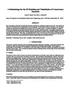
We propose a modeling methodology for designing embedded systems. In this methodology, we start from a “customer’s” requirement document that is then mapped to an activity diagram, a swimlane diagram, class diagrams, and use-case diagrams. To evolve a concurrency compliant design, we used the Message Sequence Chart plug-in for the Label Transition State Analyzer (LTSA). Later, we use MLDesigner to model and simulate our system [14].
Fig. 1: Overview of our modeling methodology.
Our modeling methodology shown in Fig. 1 has three steps. In the first step, we used UML (Unified Modeling Language) diagrams in developing our design for an RTOS. We researched into the current RTOS and its characteristics. These backgrounds help us think of an RTOS as a service provider for arriving processes. Basically, all the RTOS activities that occur while a process is being serviced were depicted in the UML activity diagram. Next, the relationship between the activities and the components of the RTOS were shown using a swimlane diagram. We further considered the relationship of a component of an RTOS with other components of the RTOS that it needed to carry out its functionalities. We displayed this information using UML
class diagrams. Each of the operations of a class in a class diagram is a scenario for a use case diagram in which a component participates with the other components as actors. In the second step of our methodology, we performed concurrency modeling. We checked our RTOS model for deadlock, safety and liveness properties. Deadlock occurs when every process is blocked in a system and the system, as a result, can make no additional progress. A safety property confirms that no error occurs while a program runs and a liveness property confirms that a progress eventually occurs. We used our UML diagrams from step 1 to help us draw MSCs using LTSA-MSC. The MSC shows the interaction between components that occur in a scenario. After creating the MSCs (hMSC and bMSC), these diagrams were synthesized to FSP code, compiled, and composed in LTSAMSC. Next, we checked for deadlock, and if there was any deadlock we modified our MSC until deadlock was resolved. After deadlock, we checked for safety property by pressing the implied scenario detection button, and this shows us if there is any property violation. Our model did not have any property violation, so we did not have any implied scenario. If there is a property violation, then a bMSC will show that implied scenario. In that case, we will decide if it is a positive (e.g., desirable scenario) or negative scenario (e.g., undesirable scenario). Also note that the MSC was not fully exploited to identify all concurrency issues across use cases, due to MSC tool constraints (memory requirements). In the third and last step, we modeled our components in MLDesigner (Mission Level Design modeling tool) to show our methodology. When moving to MLDesigner, the previous concurrency work was used as a starting point and reference for the MLDesigner model. The concurrency modeling defined what components made up the design, and what the functionality of each component was, allowing us to skip this when using MLDesigner and go straight to modeling. We were able to start off knowing exactly what we were modeling, what each component was to do, and how everything was connected. For instance, when creating the Scheduler, the fact that it needed two queues, would schedule based on priority, and was connected to the Memory Manager was known. MLDesigner was simply an implementation of that design. The only real challenge at this point was the actual translation to MLDesigner, i.e. moving the functionality from UML to MLDesigner graphical design tool. We decided to base our model on the CPU demo, since it already incorporated many of the functionalities that we needed such as the creation and consumption of a process. To this we added the extra parameters we needed. Because of this and because of the way our RTOS works, we chose to use the DE (Discrete Event) domain in MLDesigner. This models the RTOS as a system of discrete, time-stamped events. This was necessary since time is a big part of the RTOS. One of the helpful aspects about using MLDesigner was that we were able to use a number of pre-built components in our model, to directly modify our Process data structure. This shortened our development time and made it easier to get our model up and running quickly [15].
3.1. Requirements We developed our activity diagram as depicted in Fig. 2 from the point of view of a process. When a process arrives, it sends a request for memory and if the memory is unavailable, it waits in the priority queue. If the memory is available and the processor is unavailable, it waits in the ready queue for the processor to be available [15]. While the process is running on the processor and an interrupt occurs then interrupt handling takes place. If cooperation is needed from another process, the synchronizer coordinates the communication between processes. Once the process stops running, the resources are returned and the processor is once again available for other processes. The Monitor gathers information mainly from two queues, which are part of processor and Memory Manager. The Monitor provides information to the OS Manager, which in turn optimizes data flow. Next, we developed the swimlane diagram that associates the components’ names with their activities that were provided in the activity diagram. After the swimlane diagram, we move on to the class diagram that depicts the relationship of a component of the RTOS with other components to carry out certain functionalities. Master_CPU
OS_Manager 1
1
runs_on optimize_by
Scheduler Process_list:int Queue_list:int _manages
schedules
Schedules():void Assigns():void Manages():void Runs_on_Master():void
manages
assign_schedule 1
1 Process
Salve_CPU
1 Priority_Queue
1 Ready_Queue
Fig. 2: The class diagram for the scheduler.
For example, Fig. 2 shows a Scheduler which runs on the Master CPU, schedules processes, assigns scheduling policies to the Slave CPU and manages two queues. The OS Manager interacts with the Scheduler to optimize the Scheduler’s activities. The Scheduler component has two attributes, the process list and the queue list. It also has four operations: schedules, assigns, manages, and run on master, to perform its duties. Once we are done with refining the class diagram, we create use cases.
Scheduler
Schedules
Master_CPU
Runs_On_Master_CP U
Assigns
Process
Slave_CPU
Manages
Fig. 5: The bMSC for a Scheduler process.
Fig. 3: The use case diagram for the scheduler.
In the case of the Scheduler as shown in Fig. 3, components that interact with the Scheduler components are the actors that interact to perform scenarios, which are operations of the scheduler class. The Scheduler components run on Master CPU, and the Slave CPU gets the process assigned from the scheduling policy. The Scheduler maintains the scheduling policy and manages processes. If there is no interaction between an actor and the scenario, it means interaction is within the internal components and is not shown in the use case since it does not involve any actor. 3.2.
Fig. 6: The bMSC for a Ready process.
Concurrency Model for an RTOS
Scheduler: In Fig. 4, the hMSC for the Scheduler connects three bMSCs. They are the Schedule Process, Ready Process, and No Ready Process. The Schedule Process in Fig. 5 shows that the scheduler assigns schedules to Ready Queue and Priority Queue. Then the Scheduler assigns a process to the Slave CPU and starts the process. The Ready Process in Fig. 6 shows that once the process stops running, the Scheduler checks if there is another process ready to run. If there is more than one process in the Ready Queue, the scheduler selects the next process according to the assigned scheduling policy. The Scheduler assigns the selected process to run on the Slave CPU. In Fig. 7, it is shown that if there is no more ready process then the Ready Queue signals “noReadyProcess” to the Scheduler.
Fig. 7: The bMSC for a Process not Ready.
Once MSC specifications were completed, by pressing the synthesis button we generated the FSP code. The FSP code has a corresponding state machine (LTS) description. Fig. 8 illustrates the LTS (Labeled Transition System) state machine description for the interactions between Scheduler and Ready Queue.
Fig. 8: Ready Queue LTS
Fig. 4: The hMSC for the scheduler.
Fig. 9: LTSA analyzer for Scheduler
Fig. 12: The bMSC for the unavailable memory.
We can instruct the LTSA analyzer tool to find deadlock states and to produce a sample trace of how these states that can engage in no further actions can be reached from the start state. By performing a breadth-first search of the LTS graph, the LTSA tool guarantees that the sample trace is the shortest trace to the deadlock state. Fig. 9 shows the output produced by LTSA analyzer for the Scheduler model. Memory Manager: In Fig. 10, the hMSC for the Memory Manager connects bMSCs called Memory Allocation, Memory Unavailable, and Deallocates. In Fig. 11, when a process arrives, it requests memory from the Memory Manager; if memory is available, the Memory Manager assigns the memory address to the process.
Fig. 13. The bMSC to deallocate memory.
Fig. 14 illustrates the LTS state machine description for the interactions between Memory Manager and Memory. Fig. 15 shows the output when the Memory Manager model is checked using the analyzer tool LTSA and find that it reports that there is no deadlock.
Fig. 10: The hMSC for the Memory Manager.
Fig. 14: Memory LTSA.
Fig 11: The bMSC for the available memory.
In Fig. 12, if the memory is unavailable then the Memory Manager signals “outOfMemory” to the Process. In Fig. 13, once the process is done using the memory, the Memory Manager frees the memory.
Fig 15: LTSA analyzer for Memory Manager.
3.3.
MLDesigner Modeling
MLDesigner models can be used to measure different performance and quality of service characteristics, such as system performance, throughput, and delay. The RTOS will be modeled in MLDesigner in the Discrete Event domain and will use a consumer/producer model. We currently have four components modeled: the Process, the Slave CPU, the Scheduler, and the Memory Manager as shown in Fig. 16.
Fig. 18: The Slave CPU model.
Fig. 16: The RTOS system.
Consumer/Producer: The design for the RTOS in MLDesigner is based upon the “CPU Demo” example included in the software [14]. This demo models the production and consumption of packets by a single virtual CPU. The RTOS model uses a modified version of the CPU Demo’s packet creation to model software processes that “run” in the RTOS.
Scheduler: The Scheduler shown in Fig. 19 consists of a Priority Queue, its Controller, a Ready Queue, and a CPU “Manager”. The Priority Queue contains processes that are waiting for memory and sorts them based on priority. Its Controller receives memory information from the Memory Manager, and releases the next item in the queue when enough memory is available. Items in the Ready Queue are also sorted based on priority. The CPU “Manager” also functions as a manager for the Ready Queue. It keeps track of which CPUs are busy or available, releases the next item in the Ready Queue when a CPU is available and routes it to the appropriate CPU.
Fig. 17: The Process model.
Fig. 17 shows that processes are modeled as data structures that contain relevant information about the process, such as memory requirement and the amount of CPU time required. The Slave CPU component of the RTOS incorporates elements of the CPU element from this demo model. Fig. 18 shows that the Slave CPU is modeled in a basic way as a resource that is held by a process for a period of time and then freed.
Fig. 19: The Scheduler model.
Memory Manager: The Memory Manager module depicted in Fig. 20 allocates and keeps track of the memory used by the system. The Memory is modeled as a Quantity Resource that contains a certain number of units that can be allocated to a process.
Fig. 20: The Memory Manager model.
The Allocator unit attempts to assign memory to incoming processes based on priority and available memory. Processes that get their memory are sent to the Ready Queue and processes that don’t are sent to the Priority Queue. The Deallocator takes in a process that has been completed and frees the memory associated with it. The Memory Tracker keeps track of how much memory is currently available. 4.
SIMULATION RESULTS
Fig. 22: The display for completed processes.
Fig. 22 shows the resulting output of the RTOS. The first process, having a clear path through the system, is the first one completed. The rest of the processes are finished first in order of priority, then by when the system has enough free memory to run them.
Fig. 21 shows the values for the data structure fields: process ID number, priority, CPU time required, Memory needed, start time, and end time. Processes are numbered in the order they are created. The CPU time required and Memory needed are randomly generated. As the processes go through the RTOS, they are re-ordered by priority and the amount of memory needed. In MLDesigner, one is the lowest priority.
Fig. 23: The display for the Memory Manager module.
As processes are completed, their memory is freed and added back to the system pool as shown in Fig. 23. If the system has enough memory to run the next process in the queue as shown in Fig. 24, it runs it; otherwise it waits as shown in Fig. 25. These results agree with the initial UML design of the RTOS. Fig. 21: The display for created processes.
REFERENCES [1] [2] [3] [4]
[5]
[6] Fig. 24: The display for Ready Queue.
[7] [8] [9]
[10] [11] [12] Fig. 25: The display for Priority Queue.
5.
CONCLUSION
There are many advantages of using the proposed methodology. It gives customers feedback of their requirements with visual UML diagrams, performs concurrency analysis, and simulates the system model with inputs. We show that we can clearly understand the customer’s requirements by mapping it to an activity diagram and other UML diagrams, which the customer can verify. We can check our design for concurrency failures such as deadlock, safety, and livelock violation. We can simulate our model in MLDesigner, measure performance, and select components based on performance. Flexibility is another key advantage of this methodology and it can be used at different stages of the system development. We proposed that the components must be developed in an object-oriented manner. This will enable us to develop reusable and scalable components. For example, we can scale our RTOS model for different numbers of processors. The proposed methodology has the potential to enhance system design productivity as it helps in reducing design iterations from the specification and requirements phase to the design and development phase.
[13] [14] [15]
Semiconductor Industry Association, The International Technology Roadmap for Semiconductors (ITRS), 2001. http://public.itrs.net/Files/2001ITRS/Home.htm H. Sutter, “The free lunch is over: A fundamental turn toward concurrency in software”, Dr. Dobb’s Journal, 30(3), 2005. D. R. Butenhof, Programming with POSIX Threads, AdditionWesley, 1997. M. Guler, S. Clements, N. Kejriwal, L. Wills, B. Heck, and B. G. Vachtsevanos, “Rapid prototyping of transition management code for reconfigurable control systems”, 13th IEEE International Workshop on Rapid System Prototyping, 2002, pp. 76 – 83. J. Burch, R. Passerone, and A.L. Sangiovanni-Vincentelli, Overcoming Heterophobia: modelling concurrency in heterogeneous systems”, IEEE International Conference on Application of Concurrency to System Design, 2001, pp. 13 – 32. G. H. Hilderink, “Graphical modeling language for specifying concurrency based on CSP”, IEEE Proceedings on Software Engineering, 150(2), 2003, pp. 108 – 120. S. Chrobot, “Modeling communication in distributed systems”, IEEE International Proceeding in Parallel Computing in Electrical Engineering, 2002, pp. 55 – 60. T. Murphy, K. Crary, R. Harper, and F. Pfenning, “A symmetric modal lambda calculus for distributed computing”, 19th Annual IEEE Symposium on Logic in Computer Science, 2004, pp. 286 – 295 A. Girault, B. Lee, and E. A. Lee, “Hierarchical finite state machines with multiple concurrency models”, IEEE Transactions on Computer Aided Design of Integrated Circuits and Systems, 18(6), 1999, pp. 742-760. M. Barrio and P. De La Fuente, “A formal model of concurrency for distributed object-oriented systems”, IEEE International Computer Science Conference on Software Engineering, 1997, pp. 466-474. D. Sangiorgi., Expressing Mobility in Process Algebras: First-Order and Higher-Order Paradigms, PhD Dissertation, Computer Science Dept., University of Edinburgh, May 1993. J. Magee and J. Kramer, Concurrency - State Models and Java Programming, 2nd edition, Wiley, 2006. F. Hessel et al., “Abstract RTOS modeling for embedded systems”, Proceedings of the 15th IEEE International Workshop on Rapid System Prototyping, 2004. http://www.mldesigner.com/application_notes.html S. Islam, A Modeling Methodology for an RTOS, M.S. Thesis, Florida Atlantic University, May 2007.