CONCURRENT MULTIPATH TRANSFER USING TRANSPORT LAYER MULTIHOMING: PERFORMANCE UNDER NETWORK FAILURES Preethi Natarajan1, Janardhan R. Iyengar2, Paul. D. Amer1 and Randall Stewart3 1
Protocol Engineering Lab, CIS Dept University of Delaware {nataraja, amer}@cis.udel.edu
2
Dept of Math & Computer Science Connecticut College
[email protected]
3
Internet Technologies Division Cisco Systems
[email protected]
Additionally, SCTP supports fault tolerance through transport layer multihoming. An SCTP association (SCTP’s term for a transport layer connection) binds multiple interfaces at each end of the association. For example, a single SCTP association between hosts A and B in Figure 1 can bind both IP addresses at each end host: ({A1, A2}, {B1, B2}). Such an association allows data transmission from host A to be sent to either B1 or B2. The current SCTP specification designates one interface at each destination host as the primary interface, and all new data is transmitted to the primary interface. If ever the primary interface fails, new data transmission fails over to an alternate reachable destination interface.
ABSTRACT Recent research on Concurrent Multipath Transfer using SCTP multihoming (CMT) proposed various retransmission policies to minimize the negative impacts of receiver buffer (rbuf) blocking that occur during congestion. Here we investigate CMT’s throughput degradation caused by rbuf blocking during complete and/or short-term network failures. To improve CMT’s performance during failure, we introduce a new state for each destination called the “Potentially Failed” (PF) state and propose a retransmission policy that takes the PF state into account. Using simulation, we evaluate our solution (called CMT-PF), and demonstrate its improved throughput over CMT in failure-prone networks such as FCS battlefield networks.
An SCTP sender infers reachability of the receiver’s interfaces in two ways: (i) through acks of data, and (ii) through acks of heartbeats, which are periodic probes sent specifically to check a destination interface’s status. A sender detects path failures using a tunable threshold called Path Maximum Retransmit (PMR). While trying to reach a destination interface (via data or probes, or a combination thereof), the sender marks the interface as failed after (PMR + 1) consecutive timeouts. RFC2960 proposes a default PMR value of 5, which translates to 63 seconds (6 consecutive timeouts) for failure detection [9].
1. INTRODUCTION Multihoming provides added fault-tolerance at the network layer [3]. This network level fault-tolerance is crucial for mission critical systems such as Future Combat Systems (FCS) networks, where interrupted communication may be a matter of life or death. Consider for example the multihomed battlefield nodes in Figure 1. Host A or B can remain accessible even when one of their IP addresses becomes unreachable; perhaps due to intermediate routing failure on the path to the interface, failure of the interface itself, radio channel interference, or moving out-of-range. Additionally, hosts A and B may be simultaneously connected through multiple access technologies, and even multiple end-to-end paths to increase resilience to path failures.
Concurrent multipath transfer (CMT) proposes to achieve higher throughput in an SCTP association by concurrently using all independent paths between a sender and receiver for data transfer [6]. Reference [5] explores the receive buffer (rbuf) blocking problem in CMT, where TPDU losses halt the sender because the SCTP receiver’s buffer is filled with out-of-order data. Even though the congestion window would allow new data to be transmitted, rbuf blocking (i.e., flow control) stalls the sender, thus resulting in throughput degradation.
TCP does not support multihoming between two endpoints. When an end point’s IP address becomes unreachable, existing TCP connections will timeout and abort, forcing the application to recover. This recovery overhead and associated delay can be unacceptable during critical battlefield communications, where responsiveness is vital.
To alleviate rbuf blocking due to congestion loss, [5] proposes different retransmission policies that reduce the amount of outof-order data in the receive buffer. These policies consider different path properties such as loss rate and delay, and send retransmissions on a path with lower loss or delay. In practice, the loss rate of a path can only be estimated, so [5] proposes the RTX-SSTHRESH retransmission policy, where retransmissions are sent on the path with the highest slow-start threshold (a.k.a. ssthresh). However, [5] does not consider the impact of rbuf blocking on throughput during network failures, which is the focus of this paper.
The Stream Control Transmission Protocol (SCTP) [RFC2960] is an IETF (Internet Engineering Task Force) standards track transport layer protocol that provides TCP-like reliability, congestion, and flow-controlled data transfer to applications.
2. PROBLEM DESCRIPTION The following are relevant SCTP [RFC2960] facts to understand the rbuf blocking problem in SCTP with CMT (herein simply referred to as CMT) during failures:
Figure 1. Example Multihoming topology
• SCTP is message-oriented and transmits user data in chunks. Each data chunk is assigned a Transmission Sequence Number (TSN) to track order of delivery to the receiving application.
• Prepared through collaborative participation in the Communication and Networks Consortium sponsored by the US Army Research Lab under Collaborative Tech Alliance Program, Coop Agreement DAAD19-01-20011. The US Gov’t is authorized to reproduce and distribute reprints for Gov’t purposes notwithstanding any copyright notation thereon. • Supported by the University Research Program, Cisco Systems, Inc.
1 of 7
• SCTP uses delayed selective acks (SACK). The cumulative TSN in a SACK reports the highest in-sequence TSN, and the gap blocks report all the TSNs received between the cumulative TSN and the highest TSN.
the sender uses CUC and increments C2 to 3 and decrements O1 and O2 to 1. The sender now estimates available space in the rbuf for new data as the advertised window (4) – total outstanding TPDUs in the association (2). This allows the sender to send two TSNs, 5 and 6, on path 2. On path 1, even though the congestion window allows transmission of 1 TPDU, the sender cannot send data since the sender is limited by available rbuf space. This scenario depicts the receiver buffer blocking problem in CMT, where out of order data at the receive buffer prevents the sender from transmitting new data on all paths.
• Gap blocks are considered missing reports for all TSNs that have not arrived at the receiver. When a TSN is reported missing dupackthresh times (default = 3), the sender marks it for fast retransmit. • An SCTP receiver uses a single receive buffer to store outof-order TPDUs from the sender. Every SACK from the receiver advertises the current available receiver window space. On receiving a SACK, the SCTP sender subtracts the size of outstanding data from the advertised receiver window, and estimates the amount of new data that can be sent without overflowing the receive buffer.
When the SACK triggered by TSN 4 arrives, C2 increases to 4, and O2 decreases to 2. The sender calculates the peer’s available receive buffer space to be 0 (advertised receiver window – total number of outstanding TPDUs). Again, rbuf blocking prevents the sender from sending data on path 1.
• An SCTP sender has less than a full congestion window of outstanding data if the application has limited data to transfer. During such scenarios, RFC2960 dictates that a SACK with a new cumulative TSN should not increment the congestion window, since doing so is both unnecessary and might result in bursty traffic in the future. In the later part of this section, we will see how rbuf blocking can also trigger this rule.
The SACKs triggered by TSNs 5 and 6 do not increment C2 since the amount of outstanding data on path 2 is less than C2. But these SACKs decrement O2. Note that even though O2 is less than C2, the sender cannot transmit new data on path 2 due to rbuf blocking. The loss of TSN 2 on path 1 is detected by a timeout on path 1. This timeout is the first of the 6 (PMR = 5) consecutive timeouts needed to detect the failure. After the timeout, C1 is set to 1 and O1 is set to 0. RTO on path 1 is exponentially increased. CMT uses RTX-SSTHRESH policy and retransmits TSN 2 on path 2. Even though O1 is less than C1, rbuf blocking prevents data transmission on path 1.
Figure 2 is a timeline diagram of a CMT sender with two interfaces A1 and A2, transmitting data to a receiver with two interfaces B1 and B2, i.e., the configuration shown in Figure 1. The following are our assumptions for easier illustration of the problem: • In Figure 2, both the forward and reverse paths between A1 and B1 fail just after TSN 2 enters the network. For example, the wireless radio link to interface B1 goes down.
The SACK triggered by TSN 2’s retransmission advertises a receiver window of 5 to the sender, ending the current episode of rbuf blocking. The sender now transmits TSN 7 on path 1 and TSNs 8-11 on path 2. Due to failure on path 1, TSN 7 is also lost. So TSNs 8-11 arrive out-of-order and are stored in the receiver’s buffer. The SACK triggered by TSN 8 increments C2 to 5 and decrements O2 to 3. Another episode of rbuf blocking kicks in and prevents new data transmission on path 2. This new episode can end only after retransmission of TSN 7 succeeds, which happens after an RTO on path 2 (two times the initial RTO period).
• Delayed SACKs are turned off. Hence every received TPDU triggers a SACK back to the sender. • If TPDUs arrive in-order, data is immediately delivered to the receiving application. • The transport layer rbuf for this example can hold a maximum of 5 TPDUs. The contents of this buffer are listed after the reception of every TPDU.
To generalize, the CMT sender transmits new data on path 1 until (PMR + 1) number of consecutive timeouts mark path 1 as failed. Every time new data is transmitted on the failed path, data sent on non-failed paths arrive out-of-order and cause rbuf blocking. After a timeout on the failed path, CMT sender infers loss on the path. The CMT association comes out of the latest rbuf blocking instance after a successful retransmission of the lost TPDUs.
• CMT uses the RTX-SSTHRESH retransmission policy, which, in this illustration, always chooses path 2 for retransmissions. • Each TSN denotes an MTU-sized data chunk, resulting in a one-to-one correspondence between a TPDU and a TSN. • A SACK labeled denotes a cumulative TSN value of a, in-order arrival of TSNs b through c (missing report for TSNs a+1 through b-1), and an advertised receiver window of d TPDUs.
The length of an rbuf blocking instance is proportional to the timeout value on the failed path. Note that successive rbuf blocking episodes become longer due to the exponentially increased timeout value on the failed path. Rbuf blocking results in the following side-effects that degrade CMT’s throughput:
• The initial congestion window for each path is 2 MTUs. Ci denotes the congestion window in number of MTUs on path i (between Ai – Bi) and Oi denotes the number of outstanding TPDUs on path i. In Figure 2, when path 1 fails, both TSN 2 and the SACK for TSN 1 are lost. On path 2, TSNs 3 and 4 arrive out of order at the receiver, and are stored in the rbuf. Both TSNs 3 and 4 trigger a SACK to the sender. CMT uses the CUC algorithm [6] to decouple a path’s congestion window evolution and TSN order of delivery. On receiving the SACK triggered by TSN 3,
Preventing congestion window growth: Rbuf blocking prevents a CMT sender from transmitting new data, resulting in lesser outstanding data than is allowed by the congestion window. In such cases, RFC2960 prevents the sender from increasing the congestion window for future SACKs. For example, in Figure
2 of 7
2, when SACKs for TSNs 5, 6, 9, 10, 11 arrive at the sender, the sender cannot increment C2.
PMR > 0. Also, a tradeoff exists on deciding the value of PMR--a lower value reduces rbuf blocking, whereas a higher value is more robust for failure detection in a wide range of environments.
Figure 3. CMT-PF during failure: Less Rbuf blocking In CMT, rbuf blocking cannot be eliminated [5]. RTXSSTHRESH and other retransmission policies use heuristics that alleviate its effects during congestion losses. However, these policies do not consider path failures.
Figure 2. CMT during failure: Rbuf blocking Reducing congestion window: An SCTP sender avoids bursts by using a Congestion Window Validation algorithm similar to [10]. Whenever a sender has new data to send, it uses the MaxBurst parameter (recommended value of 4) as follows:
Figure 4 is a finite state machine specifying the failure detection process in CMT. As shown, a path is in one of the two states – active or failed (inactive). A path is active as long as acks arrive for data or heartbeats sent on the path. When an active path experiences (PMR + 1) consecutive timeouts, it transitions to the failed state, where only heartbeats are sent. The failed path returns to the active state once the sender receives an ack for a heartbeat.
If ((outstanding + MaxBurst * MTU) < Cwnd) Cwnd = outstanding + MaxBurst * MTU This algorithm reduces the congestion window during idle periods so that at the next sending opportunity, the sender cannot transmit more than (MaxBurst * MTU) bytes of data in a burst. During an instance of rbuf blocking, the amount of outstanding data can go well below the congestion window. In such cases, the above rule gets triggered, further reducing the congestion window. In Figure 2, when the SACK triggered by TSN 11 arrives at the sender, O2 decrements to 0. The window validation algorithm causes C2 to be reduced to 4 (O2 (0) + MaxBurst (4)).
To mitigate the recurring instances of rbuf blocking, we introduce a path state called “potentially failed”. Loss detected by a timeout implies either severe congestion or failure on the path. After a single timeout on the path, a sender is unsure, and marks the path as “potentially failed” (Figure 5). A “potentially failed” path is not used for data transmission (or retransmission) since transferring data on a failed path results in recurring episodes of rbuf blocking.
3. PROPOSED RETRANSMISSION POLICY Reference [9] recommends lowering the value of PMR for SCTP flows in Internet-like environments. Correspondingly, lowering the PMR for CMT flows reduces the number of rbuf blocking episodes, and thus CMT’s throughput degradation during failures. However, lowering the PMR is an incomplete solution to the problem since rbuf blocking happens for any
We augment CMT’s RTX_SSTHRESH policy---one of the recommended loss rate based retransmission schemes [5]---to include the “potentially failed” (PF) state, and call it CMT-PF. The details of CMT-PF are: •
3 of 7
If a TPDU loss on a path is detected by dupackthresh missing reports, use the RTX_SSTHRESH retransmission policy to select any of the active paths for retransmission.
•
If a TPDU loss on a path is detected by timeout, the path transitions to the PF state (Figure 5). A path in the PF state is not used for transmitting any data. (Exception: if all paths in an association are in the PF state, data is still sent on the path with the least errorcount, i.e., the path with the lowest number of consecutive timeouts. If errorcounts of all paths are the same, data is sent on the last active path. This exception ensures that CMT-PF does not perform worse than CMT when all paths have possibly failed.
•
After the initial timeout, heartbeats are sent on the PF path, with exponential backoff of RTO when timeout occurs, until (i) an ack for a heartbeat transitions the path back to the active state, or (ii) an additional PMR consecutive timeouts on heartbeats confirm the path as failed, after which the path transits to failed, and heartbeats are sent with the frequency described in RFC2960.
•
Once a heartbeat ack indicates the PF path is alive, its congestion window is set to either 1 MTU (CMT-PF1), or 2 MTUs (CMT-PF2), and data transmission follows slow start phase. (A discussion of CMT-PF1 vs. CMT-PF2 occurs at the end of this section.)
•
Arrival of acks for retransmissions of timed-out data, do not transition a PF path to the active state, since there is ambiguity in deciding whether the ack was for the original transmission or the retransmission(s).
Fig ure 4. CMT failure detection
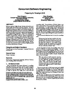
Figure 3 depicts the CMT-PF timeline diagram for the scenario described in Figure 2. All events are identical up to the first RTO for TSN 2 on path 1. After this timeout, path 1 transitions to the PF state. TSN 2 is retransmitted on path 2. On path 1, RTO exponentially backs off and a heartbeat is sent. Due to failure on path 1, this heartbeat is lost. The loss is detected by a timeout which will be the second of the (PMR + 1) number of consecutive timeouts required to mark path 1 as failed. Meanwhile, receiver buffer space is released once TSN 2 reaches the destination on path 2. From this point onwards, data is transmitted on path 2 alone, preventing further rbuf blocking. Since rbuf blocking is reduced, we expect CMT-PF to provide higher throughput than CMT during path failures.
Figure 5. CMT-PF failure detection Sender is not limited by rbuf before and after the timeout: With CMT, the congestion window on p allows the sender to send 1 MTU worth of retransmission or new data. The SACK triggered by this data will increment p’s congestion window by 1 MTU. Therefore, at the end of 1 RTT after the timeout, (i) the congestion window on p will be 2 MTUs, and (ii) 1 MTU worth of new data has been successfully sent on p (Figure 6).
We now consider the case when timeout on a path, say p, is due to congestion rather than failure. For our analysis, we assume that congestion clears just before the sender experiences timeout, so that data or heartbeats sent on p after the timeout reach the receiver. Depending on rbuf size and the different paths’ characteristics, the sender may or may not be rbuf blocked before the timeout, leading to the following two scenarios:
In CMT-PF, no data is sent on the PF path, p, after the timeout. CMT-PF sends a heartbeat on p and retransmits lost TPDUs along with new data on other active paths. Path p is marked active when the heartbeat ack arrives at the sender. Therefore, at the end of 1 RTT after the timeout, (i) congestion window on p is 1 MTU (CMT-PF1) and (ii) no new data has been sent on p (Figure 7). Thus, CMT has a 1 RTT “lead” in its congestion window evolution. Assuming no further losses on p, at the end of n RTTs in slow-start after the timeout, congestion window on p will be 2n with CMT, and 2n-1 with CMT-PF1.
Sender is limited by rbuf before the timeout: This scenario is similar to the failure scenario described in Sections 2 and 3 for CMT and CMT-PF, respectively. Both CMT and CMT-PF senders cannot send new data on any path until the rbuf blocking is cleared. The senders try to retransmit the lost TPDUs, which are no longer outstanding. The only difference is that CMT considers p for retransmissions, (similar to Figure 2), whereas CMT-PF will not (Figure 3), since a CMT-PF sender will transmit only heartbeats on p. Both CMT and CMT-PF can send new data only when a SACK advertising enough receiver window space arrives.
To avoid the 1 RTT lag in CMT-PF1’s congestion window evolution, we propose CMT-PF2 (see Figure 8) which initializes the congestion window to 2 MTUs after a heartbeat ack arrives. Assuming that today’s Internet router queues deal with packets rather than bytes, the successful routing of a heartbeat PDU is equivalent to the successful routing of a data
4 of 7
PDU. Hence, a heartbeat ack can be used to clock the transport layer sender in the same way as a data ack. We hypothesize that CMT-PF2 will perform on par with CMT in case of timeouts due to congestion.
When path 2 fails, all TPDUs and acks transmitted over the path are lost, causing the sender to experience back-to-back timeouts. Both CMT and CMT-PF experience the first timeout on path 2 at around 6.03 seconds, and detect path 2 failure after 6 back-to-back timeouts (PMR = 5), at around 69 seconds.
Figure 6. CMT data transfer when no rbuf blocking
Figure 8. CMT-PF2 data transfer when no rbuf blocking
Figure 9. Simulation Topology After the first timeout, CMT-PF transitions path 2 to the PF state and transmits only heartbeats on the path and avoids further rbuf blocking due to the failure. The reduction in rbuf blocking helps CMT-PF to complete the file transfer (~ 15 seconds) using path 1 alone, even before path 2 failure is detected (Figure 10). On the other hand, CMT transmits data on path 2 after each timeout during failure detection, causing recurring rbuf blocking instances. Thus, CMT experiences throughput degradation until 69 seconds, after which CMT uses path 1 alone and completes the 8MB transfer at around 80 seconds.
Figure 7. CMT-PF1 data transfer when no rbuf blocking 4. EVALUATION OF CMT-PF vs. CMT We implemented CMT-PF in the University of Delaware’s SCTP/CMT module for the ns-2 network simulator [7,8]. The simulation topology is shown in Figure 9. A multihomed sender, A, has two independent paths to a multihomed receiver, B. The edge links between A or B to the routers represent lasthop link characteristics. The end-to-end one-way delay is 45ms on both paths, representing typical coast-to-coast delays experienced by significant fraction of the flows in the Internet [11]. We believe that the conclusions in this paper are independent of the actual bandwidth and delay configurations, as long as these configurations are the same on both paths.
4.2 During Short-term Failure We perform two experiments where path 2 fails for a brief period (from 5 to 10 seconds) after start of an 8MB file transfer between hosts A and B. In the first short-term failure experiment, no losses occur on either path. Path 2 failure from 5 to 10 seconds causes three back-to-back timeouts on the path. As in the failure case, CMT tries to send data after each of these timeouts on path 2. The resulting rbuf blocking in CMT, prevents the efficient use of path 1 for data transfer, and lowers CMT throughput when compared to CMT-PF (Figure 11). Once path 2 recovers at 10 seconds, CMT’s data and CMT-PF’s heartbeat transmissions on the path (after the 3rd timeout ~12.5 seconds) are successful, and both CMT and CMT-PF complete the file transfer without
4.1 During Permanent Failure We perform a simple experiment to understand the elementary differences between CMT and CMT-PF during permanent path failures. In this experiment, path 2 fails after 5 seconds from the start of an 8MB file transfer from A to B. We simulate path 2 failure by bringing down the link between routers R20 and R21. The receiver buffer is set to 64KB and there are no congestion losses on either path.
5 of 7
further rbuf blocking. In Figure 11, CMT-PF2 performs slightly better than CMT-PF1 just after path 2 is marked active, since CMT-PF2 has a 1 RTT lead in congestion window evolution. This fine difference between the two PF variations becomes visible upon closer inspection.
As explained in Section 3, after experiencing a timeout on a path, CMT and CMT-PF behave differently. While CMT considers the path for data transmission, CMT-PF transitions the path to the PF state and does not send data on the path until marked active. With losses occurring due to congestion, we expected CMT to outperform CMT-PF since CMT is able to transmit more data than CMT-PF after a timeout occurs.
In the second short-term failure experiment, we study the performance differences between CMT and CMT-PF under varying rbuf constraints. The goal is to observe how CMT-PF’s gains over CMT are related to the rbuf size. In this experiment, both paths experience a low 1% loss rate, and host A transfers an 8MB file to host B. Figure 12 plots the average throughput with a 5% error margin, measured during the 5 second shortterm failure for various rbuf values. Since rbuf blocking increases as the rbuf size decreases [5], CMT-PF’s throughput improvement over CMT increases as rbuf size decreases. Again, the differences between CMT-PF1 and CMT-PF2 are very negligible in this experiment.
Figure 12. Throughput during short-term failure
Figure 10. Throughput during failure detection
Figure 13. Transfer time during congestion When a path’s loss rate is low, most of the TPDU losses on the path can be recovered through fast retransmits, resulting in very few timeout recoveries. Hence, in Figure 13, when path 2 loss rates are lower, the number of timeout recoveries on path 2 are low, and no substantial performance difference between CMT and CMT-PF can be observed.
Figure 11. Throughput during short-term failure
With increase in path 2 loss rates, the number of timeouts on path 2 increases. Counter to our expectation, Figure 13 shows that both CMT-PF1 and CMT-PF2 perform slightly better than CMT when the paths’ loss rates are asymmetric! The reason is as follows. High loss rates on path 2 induce back-to-back timeouts on the path. During loss recovery via timeout, if the sender is rbuf blocked, the length of this rbuf blocking period is
4.3 During Congestion We perform a final set of experiments to study CMT-PF performance when timeouts on a path are due to congestion rather than failure. Path 1 has a fixed loss rate (1%) and path 2’s loss rate varies from 1-10%. The receive buffer is set to 64KB and Figure 13 plots CMT and CMT-PF’s transfer times with a 5% margin of error, for an 8MB file.
6 of 7
proportional to the timeout recovery (RTO) period. Back-toback timeouts result in exponentially increasing RTO values. Hence, consecutive timeouts on data result in exponentially increasing rbuf blocking periods that increase the overall file transfer time.
5. CONCLUSION AND FUTURE WORK We investigated rbuf blocking and the associated throughput degradation in CMT, caused by complete and short-term failures. To improve CMT performance during failures, we proposed CMT-PF. CMT-PF includes a new destination state called the “Potentially Failed” (PF) state, and enhances CMT’s retransmission policies to include the PF state.
Figure 14 tabulates the number of retransmission timeouts on data for CMT, CMT-PF1 and CMT-PF2, observed in our simulation runs when path 2 loss rate = 10%. Timeout recovery periods of 2, 4 and 8 seconds are due to the exponentially backed off RTO values at the end of 2, 3 and 4 consecutive timeouts respectively. The table shows that while CMT experiences some 2, 4 and 8 second timeout recovery periods, both CMT-PF1 and CMT-PF2 do not experience any, implying that CMT-PF does not suffer back-to-back timeouts on data in these simulation runs. CMT-PF marks a path as PF after a single timeout and only heartbeats are transmitted on the PF path. Hence, at high loss rates on path 2, the subsequent timeouts on the path are for heartbeats and not for data.
Using simulations, we evaluated CMT-PF under different failure scenarios that are characteristic of battlefield FCS networks, and demonstrated CMT-PF’s throughput gains over CMT during those failure scenarios. We also demonstrated how CMT-PF’s ability to avoid back-to-back timeouts on data improves its performance over CMT when the paths have asymmetric loss rates. In the future, we will identify congestion scenarios as discussed in Section 4.4 and evaluate CMT-PF under those scenarios. We will also evaluate CMT-PF vs. CMT during asymmetric path delays and during congestion created by cross-traffic as opposed to random losses.
During back-to-back timeout periods for heartbeats on path 2, CMT-PF (re)transmits data on the lower loss rate path 1 alone, and thus avoids any extended or recurring rbuf blocking periods. Thus, CMT-PF performs better than CMT when paths have asymmetric loss rates.
6. DISCLAIMER The views and conclusions contained in this document are those of the authors and should not be interpreted as representing the official policies, either expressed or implied, of the Army Research Laboratory or the U. S. Government. 7. REFERENCES [1] R. Stewart, Q. Xie, K. Morneault, C. Sharp, H. Schwarzbauer, T. Taylor, I. Rytina, M. Kalla, L. Zhang, V. Paxson, “Stream Control Transmission Protocol,” RFC 2960, 10/00 [2] R. Stewart, Q. Xie, “Stream Control Transmission Protocol (SCTP): A Reference Guide,” Addison Wesley, 2001, ISBN: 0-201-72186-4 [3] R. Braden, “Requirements for Internet hosts – communication layers,” RFC1122, 10/89
Figure 14. Distribution of timeout recovery periods for data (path 2 loss rate = 10%)
[4] Stream Control Transmission Protocol, www.sctp.org/ [5] J. Iyengar, P. Amer, R. Stewart, “Receive buffer blocking in concurrent multipath transfer,” GLOBECOM 2005, St. Louis, 11/05
4.4 Discussion In Section 4.3 we demonstrated how CMT-PF’s ability to avoid back-to-back data timeouts on a highly congested path, improves its performance over CMT, when the other path(s) experience lower loss rates. To be more precise, let x be CMTPF’s total gain in transfer time when it avoids back-to-back data timeouts during a bulk transfer. Let y be the time CMT-PF wastes by not using a PF path during the data transfer. CMTPF’s improvement over CMT in Section 4.3 was because x was greater than y. Hence, we now hypothesize that CMT-PF could perform worse than CMT in the following congestion scenarios: •
•
[6] J. Iyengar, P. Amer, R. Stewart, “Concurrent multipath transfer using SCTP multihoming over independent end-toend paths,” IEEE/ACM Trans on Networking, 12/06 [7] ns-2 documentation and software, Version 2.1b8, 2001, www.isi.edu/nsnam/ns. [8] A. Caro and J. Iyengar, “ns-2 SCTP module,” Version 3.6, June 2006, http://pel.cis.udel.edu. [9] A. Caro. End-to-end Fault Tolerance using Transport Layer Multihoming. PhD Dissertation, CIS Dept. U of Delaware.
(x = 0) and (y > 0): During the complete file transfer, congestion on a path is such that there are no back-to-back timeouts on the path. All timeouts are singleton and CMTPF wastes time by not using a PF path for data transfer (y > 0) after every timeout.
[10] M. Handley, J. Padhye, S. Floyd, “TCP Congestion Window Validation,” RFC2861, 06/00 [11] S. Shakkottai, R. Srikant, A. Broido, k. claffy, “The RTT distribution of TCP Flows in the Internet and its Impact on TCP-based flow control,” Tech. Rep., Cooperative Association for Internet Data Analysis (CAIDA), 02/04
Generally, (x < y): At the end of the data transfer, CMTPF’s gain in transfer time is smaller than the time CMT-PF lost by not using a PF path for data transfer.
We are currently investigating the plausibility of such congestion scenarios.
7 of 7