This replication scheme is then used as the core of an online concurrent test ...... could also be used to rearrange the implementation of currently executing ...
Concurrent replication of active logic blocks: A core solution for online testing and logic space defragmentation in reconfigurable systems Manuel G. Gericota1, Gustavo R. Alves1, Miguel L. Silva2, José M. Ferreira2,3 1
Department of Electrical Engineering – DEE/ISEP Rua Dr. António Bernardino de Almeida, 4200-072 Porto – PORTUGAL {mgg, galves}@dee.isep.ipp.pt 2
Dep. of Electrical and Computers Engineering – DEEC/FEUP Rua Dr. Roberto Frias, 4200-465 Porto – PORTUGAL {mlms, jmf}@fe.up.pt 3
Institutt for datateknikk - Høgskolen i Buskerud Frogsvei 41 - 3601 Kongsberg – NORWAY ABSTRACT
Partial and dynamically reconfigurable SRAM-based FPGAs (Field Programmable Gate Arrays) enable the implementation of reconfigurable systems hosting several applications simultaneously, which share the available resources according to the functional requirements that are present at any given moment. Time and space sharing strategies enabled the concept of virtual hardware, supporting the concurrent implementation of applications which would otherwise require far more complex resources. However, the performance of these applications (e.g. execution speed and reliability, activation delay) is directly influenced by the efficiency of the management strategies that allocate the logic space to the various functions that are waiting to be activated (each function requiring a specific amount of logic resources). Because the activation requests are in most cases not predictable, all resource allocation decisions have to be made online. The consequences of such working contexts are twofold:
All FPGA resources must be tested regularly, to exclude malfunctioning due to the allocation of faulty elements. Since the process of launching / halting active functions takes place asynchronously at any given moment, an online concurrent test scheme is the only way of ensuring reliable system operation and predictable fault detection latency;
As the resources are allocated to functions and later released, many small “islands” of free resources are created. If these areas become too small, they will be left unused due to routing restrictions. The defragmentation of the FPGA logic space must therefore be carried out regularly, to avoid the wasting of logic resources. This paper presents a non-intrusive solution for the concurrent replication of active logic blocks (i.e. logic blocks that are being used to implement part of an active function), transferring their functionality to fault-free resources that are available in the FPGA logic space. This replication scheme is then used as the core of an online concurrent test strategy that scans the complete FPGA, reusing the available 1149.1 test infrastructure to carry out a structural test of each logic block that has just been released. The overhead of the proposed solution, in terms of the number of configurable logic resources required for its implementation, as well as its performance (e.g. the resulting fault detection latency), are quantified. Further to the test aspects, an online concurrent defragmentation strategy based on the same replication scheme is also proposed. A rearrangement of the available logic space is carried out by selectively releasing active logic blocks, with the objective of enforcing the adjacency of those blocks that share the implementation of a common function, and the creation of wider pools of logic resources that may be used to implement new functions.
1. INTRODUCTION Reconfigurable logic devices, namely Field Programmable Gate Arrays (FPGAs), experienced a considerable expansion in the last few years due in part to an increase in their size and complexity, with advantages in terms of board space and flexibility. The availability of SRAM-based FPGAs supporting fast run-time partial reconfiguration (e. g. the Virtex family from Xilinx used to validate this work) considerably reinforced these advantages, wide-spreading their usage as a base for reconfigurable computing platforms. Partial and dynamically reconfigurable FPGAs enable the implementation of virtual hardware as defined in [1] ten years ago, by using temporal partitioning to implement those applications whose area requirements exceed the reconfigurable logic space available (i.e. to assume the availability of unlimited hardware resources). The static implementation of a circuit is separated in two or more independent hardware contexts, which may be swapped during runtime [2]. Extensive work was done to improve the multi-context handling capability of these devices, by storing several configurations and enabling quick context switching [3, 4]. The main goal was to improve the execution time by minimising external memory transfers, assuming that some amount of on-chip data storage was available in the reconfigurable architecture. However, this solution was only feasible if the functions implemented on hardware were mutually exclusive on the temporal domain, e. g. contextswitching between coding/decoding schemes in communication, video or audio systems; otherwise, the length of the reconfiguration intervals would lead to unacceptable delays in most applications. Smaller submicron scales contributed significantly to eliminate these restrictions, by enabling higher levels of integration and higher frequencies of operation. The increasing amount of logic available in FPGAs and the reduction of the reconfiguration time, partly due to the possibility of partial reconfiguration, extended the concept of virtual hardware to the implementation of multiple applications sharing the same logic resources in the spatial and temporal domains. However, smaller submicron scales also have disadvantages: they increase the threat of electromigration, due to higher electronic current density in metal traces. After large periods of operation, some manufacturing imperfections that are not large enough to influence initial testing, become exposed, emerging as permanent faults [5]. On the other hand, lower threshold voltages make these components more susceptible to gamma particle radiation and to the appearance of transient faults. Interference from such radiation is much more likely with larger FPGA dies, increasing the probability of failure modes that are seen by the system as permanent faults [6, 7]. To increase the reliability of reconfigurable systems, transparent online FPGAs test methodologies, able to cover both permanent and transient faults, must be made available. In the case of permanent faults, and after the faulty elements are located – either CLBs (Configurable Logic Blocks) or routing resources –, they must be excluded and replaced by previously unused fault-free FPGA resources. For transient faults, online partial reconfiguration enables the recovery of errors in the on-chip configuration memory cells that modify the logic functionality, namely Single Event Upsets (SEUs). Such errors manifest themselves as permanent faults because of the change in functionality, and cannot be recovered by traditional transient fault recovery techniques, such as rollback or roll-forward. However, the cause of the failure is actually transient [8]. A higher level of dependability for reconfigurable systems can therefore only be achieved through the continuous testing of all FPGA resources, and by the introduction of error correction / fault tolerance features. Using the same partial Run-Time Reconfigurable (RTR) features of new FPGA devices that originated this test challenge, a novel online testing approach, based on a rotation strategy of the resources under test, is presented in this paper, with the following main characteristics: 1) it is the first truly non-intrusive CLB test method proposed in the literature; 2) it is able to detect any permanent structural fault in the CLB emerging during system lifetime; 3) it is able to correct transient faults affecting the CLB functionality; 4) no FPGA I/O pins are occupied with test functions since its complete implementation is based on the IEEE 1149.1 Boundary Scan (BS) infrastructure [9]. There is, however, another problem that may degrade the performance of reconfigurable systems. The availability of free logic space to implement new incoming functions, when needed by those applications that are currently running, is crucial to avoid execution delays. If the sequence of functions to be activated is unpredictable, a proper implementation schedule cannot be established beforehand, and will inevitably lead to a fragmentation of the logic space. As a consequence, the lack of enough contiguous free resources will delay the implementation of new functions, even when the total amount of free resources spread across the FPGA is sufficient. A relocation of the functions that are currently implemented is therefore necessary, in order to defragment the FPGA logic space, and to create areas of contiguous free resources that are large enough to receive the new functions.
This paper proposes an innovative solution that releases occupied resources by replicating their functionality in a nonintrusive way, enabling online concurrent test and logic space defragmentation without disturbing the operation of the system. 2. TEST METHODOLOGIES FOR FPGAS BASED SYSTEMS Several off-line and online strategies have been proposed to test and diagnose FPGA faults. An off-line Built-In Self-Test (BIST) technique that exploits the FPGA reprogrammability features in order to set up the BIST logic is presented in [10-12]. Some of the logic blocks are configured as pattern generators or response analyzers, while testing the other blocks, and vice-versa. Since the test sequences are a function of the FPGA architecture and independent of its functionality, this approach is applicable at all levels (wafer, packaged device, board, and system). This technique requires a fixed number of reconfiguration sessions and presents no area overhead or performance penalty, since the BIST logic is eliminated when the circuit is reconfigured for normal operation. A slightly different BIST technique, which implies a structural modification of the original configuration memory, is proposed in [13]. When compared to similar BIST techniques, this method reduces test time and the required off-chip memory, while enabling the automation of the test process. However, the modification required at the internal hardware level of the FPGA is a major disadvantage, implying the non-universality of the solution. An off-line test methodology based on a non-BIST approach, targeted to test the FPGA CLBs, is presented in [14, 15]. After a specific test configuration is set up, the FPGA Input/Output Blocks (IOBs) are used to support the external application of test vectors and to capture the test responses. In order to achieve 100% fault coverage at CLB level, and due to the configurable features of the FPGAs, different test configurations must be programmed and specific sets of test vectors applied in each case. Based on the same principles, a fault diagnosis method is presented in [16]. Extensive work on the structural testing of FPGA Look-Up Tables (LUT) and interconnections are also presented in [17, 18]. The previous approaches are restricted to manufacturing test, since they require the device to be off-line, increasing faultdetection latency, which may not be admissible in highly fault-sensitive, mission-critical applications. In order to overcome these limitations, online testing and diagnosis methods based on a scanning strategy were presented in [5, 19]. The idea underlying these methods is to have only a relatively small portion of the chip being tested off-line (instead of the whole chip, as considered in previous proposals), while the rest continues its normal online operation. Testing is accomplished by sweeping the test functions across the entire FPGA. If the functionality of a small number of FPGA elements can be relocated on another portion of the device, then those elements may be taken off-line and tested in a completely transparent way. This fault scanning procedure then moves on to copy and test another set of elements, sweeping through the whole FPGA, systematically testing for faults. However, in the first approach [5], a modification in the structure of the FPGA cells is required to implement the replication procedure. On the other hand, in the second approach [19], known as Roving STARs (Self-Testing Areas), the whole system must be stopped in order to relocate an entire CLB column. Since reconfiguration is performed through the BS infrastructure, reconfiguration time is long, and it seems likely that halting the system will disturb its operation. The design for test features proposed in [20] are essentially concerned with error detection, instead of carrying out any structural or functional test functions (the FPGA logic structure is not taken into account). Their main goal consists of detecting the presence of faults in the current application, and therefore a given defect may escape detection, according to the application that is presently running. A new application-oriented method that generates a functional test for the configured circuit, while considering the logic structure of the FPGA where it is implemented, was proposed in [21]. This method corresponds to an off-line field-oriented test to be used with a given application, thus presenting the same drawbacks of the method that was previously referred. The online test approach proposed in this paper reuses some of the previous ideas, but eliminates their drawbacks by using a new concept – active replication – which enables the relocation of the functionality attributed to each CLB, without halting the system. This approach is feasible even when the CLB is active, i.e. when it is part of an implemented function that is actually being used by the system [22]. A dynamic rotation mechanism ensures that all FPGA CLBs are released and tested within a given latency. The exclusive (re)use of the BS test infrastructure to release and test the CLBs brings the additional benefit of reduced overhead at board level, since no other resources (other than those of the FPGA itself) are used. Being applicationindependent, and oriented to test the FPGA structure, the proposed strategy guarantees FPGA reliability after many reconfigurations, thus helping to ensure correct operation throughout the system lifetime.
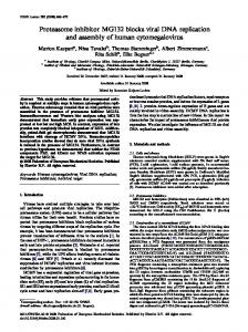
Conceptually, an FPGA may be visualized as an array of uncommitted CLBs, surrounded by a periphery of IOBs, which are interconnectable by configurable routing resources. A set of memory cells that lies beneath controls the configuration of the whole structure, as shown in figure 1.
CLB
CLB
CLB
CLB
CLB
CLB
CLB
CLB
CLB
CLB
CLB
CLB
CLB
CLB
CLB
CLB
CLB
CLB
CLB
CLB
CLB
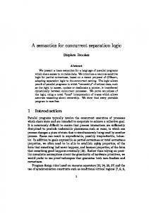
Figure 1: Schematic representation of an FPGA On a given application, total (100%) usage of the FPGA resources is hardly ever achieved, even when independent hardware blocks dynamically share the same device (in the case of a dynamically reconfigurable hardware system). As such, a few blocks will always be free. Therefore, it is possible to test temporarily unused blocks, without disturbing system operation, by taking advantage of the dynamic and partially reconfigurable features that are offered by newer FPGAs. After being tested, unused defect-free CLBs remain available as spare blocks, ready to replace others that are eventually found defective. Through a dynamic rotation mechanism the CLBs currently being used are released for testing, after their current functionality is relocated into other CLBs already tested. For simplicity of analysis the proposed approach is divided in three parts: 1. the replication procedure; 2. the dynamic rotation mechanism; 3. the testing strategy. Each of these phases will be presented in detail in the following sections. 3. CONCURRENT REPLICATION OF ACTIVE LOGIC BLOCKS The release for testing of active CLBs requires their replication into CLBs already tested and available, in such a way as to be completely transparent to the application(s) that are currently running. This task is not trivial due to two major issues: i) configuration memory organization, and ii) internal state information. The configuration memory may be visualized as a rectangular array of bits, which are grouped into one-bit wide vertical frames, extending from the top to the bottom of the array. The atomic unit of configuration is one frame — it is the smallest portion of the configuration memory that can be written to or read from. These frames are grouped together into larger units called columns. Each CLB column has an associated configuration column, with multiple frames, which mixes internal CLB configuration and state information, and column routing and interconnect information. The organization of the entire configuration memory into frames enables the online concurrent partial reconfiguration of the FPGA. A representation of the configuration memory frame partitioning is shown in figure 2.
Centre Column (8 frames)
CLB column (48 frames)
CLB column (48 frames)
2 2 2 IOBs GCLK IOBs
2 IOBs
Cn
C2
C0
C1
Cn-1
Right IOB column (54 frames)
CLB column (48 frames)
2 IOBs
Block SelectRAM content (64 frames)
2 IOBs
Block SelectRAM interconnect (27 frames)
2 2 2 IOBs GCLK IOBs
CLB column (48 frames)
Block SelectRAM interconnect (27 frames)
Block SelectRAM content (64 frames)
Left IOB column (54 frames)
Cn+2 RAM0 Cn+4
2 IOBs
Cn+3 RAM1 Cn+1
n - number of CLB columns in the FPGA
Figure 2: Configuration memory organization The configuration process is a sequential mechanism that spans through some (or eventually all) CLB configuration columns. More than one column may be affected during the replication of an active CLB, since its input and output signals (as well as those in its replica) may cross several columns before reaching its source or destination. Any partial reconfiguration procedure must ensure that the signals from the replicated CLB are not broken before being totally reestablished from its replica. It is also important to ensure that the functionality of the CLB replica must be perfectly stable before its outputs are connected to the system, so as to avoid output glitches. A set of experiments performed with a Virtex FPGA from Xilinx demonstrated that the replication process must be divided into two phases, as illustrated in figure 3. In
In
replicated Out CLB
In
Out
In
CLB replica
1st phase
replicated Out CLB CLB replica
Out
2nd phase - Routing array
Figure 3: Two-phase CLB replication process In the first phase, the internal configuration of the CLB is copied and the inputs of both CLBs are placed in parallel. Due to the low-speed characteristics of the configuration interface used (the BS interface), the reconfiguration time is relatively long when compared with the system speed of operation. Therefore, the outputs of the CLB replica will be perfectly stable before being connected to the circuit, in the second phase. Both CLBs must remain in parallel for at least one system clock cycle, to avoid output glitches. Notice that rewriting the same configuration data does not generate any transient signals, so the remaining resources covered during this process by the rewritten configuration frames are not affected. Another major requirement for the success of the replication process is the correct transferal of state information. If the current CLB function is purely combinational, a simple read-modify-write procedure will suffice to accomplish the replication process. However, in the case of a sequential function, the internal state information must be preserved and no write-operations may be lost while this process goes on. In the Virtex FPGA family, each CLB comprises four logic cells with one register each, which can be configured as a latch or flip-flop. Although it is possible to read the value of a register, it is not possible to perform a direct write operation. Moreover, when dealing with active CLBs, if state information changes, between read and write operations, a coherency problem will result. By this reason, no time gap between the two operations may exist. The solution to this problem depends on the type of implementation. In this paper three implementation cases are considered: 1. synchronous free-running clock circuits; 2. synchronous gated-clock circuits, and; 3. asynchronous circuits. When dealing with synchronous free-running clock circuits, the two-phase replication process that was previously described solves this problem. Between the first and the second phase, the CLB replica has the same inputs as the replicated CLB and all its four flip-flops acquire the state information, even if the system clock frequency is an order of magnitude lower than the clock frequency of the BS infrastructure, which is used for reconfiguration purposes. Several experiments made using this class of circuits have shown the effectiveness of this method in the replication of active CLBs. No loss of state information or the presence of output glitches was observed. Notice that this procedure is valid even when
dealing with asynchronous circuits, like the ripple counter illustrated in figure 4, if the slowest “clock” period (CLKn) is higher than the time interval between the first and the second phases.
D
Q
D
Q
D
CLK1
CLK0
Q
CLKn A0
A1
An
Figure 4: Ripple counter Despite the effectiveness of this solution, its usefulness is very restricted. A broad range of applications use synchronous gated-clock circuits, instead of free-running clocks, where input acquisition by the flip-flop is controlled by a clock enable signal. In such cases, it is not possible to ensure that this signal will be active during the replication process, and that the value at the input of the replica flip-flops will be captured. On the other hand, it is not feasible to set this signal as part of the replication process, because the value present at the input of the replica flip-flops might differ from the one captured by the replicated flip-flops, in which case a coherency problem will occur. Furthermore, the state of the flip-flops could be updated during the replication process. A replication aid block is used to solve this problem. This block manages the transferal of state information from the replicated flip-flops to the replica flip-flops, while enabling its update by the circuit, at any moment, without losing new state information or delaying the replication process. The whole replication scheme is represented in figure 5 for a single CLB cell (for this purpose each of the four logic cells of a CLB in a Virtex FPGA can be considered individually), while figure 6 represents the flow diagram of the replication process. Replica cell LOGIC_OUT
Logic
Replication aid block 1 0
CC
0 1
D
Q
CE BY_C
R
D Q
Replicated cell A1...A4
FF_OUT
Logic
0 1
D
Q
to the circuit
CE
from the circuit
R CE CLK RESET
Figure 5: Implementation of the synchronous gated-clock flip-flop replication scheme The inputs of the 2:1 multiplexer present in the replication aid block receive one temporary transfer path from the output of the replicated flip-flop (FF_OUT), and another one from the output of the combinational logic block configured in the replica cell (LOGIC_OUT), which is normally applied to the input of the flip-flop. If the clock enable (CE) signal – controlling the multiplexer – is not active, the output of the replicated flip-flop (FF_OUT) is applied to the input of the replica flip-flop. A clock enable signal, generated by the replication aid block (capture control signal - CC), forces the replica flip-flop to store the transferred value. The replica flip-flop acquires the state information present in the replicated flip-flop. If the CE signal is active or is activated during this process, the multiplexer selects the LOGIC_OUT signal and applies it to the input of the replica flip-flop, which is updated at the same time and with the same value as the replicated flip-flop, therefore guaranteeing state coherency. Figure 7 shows the simulation of state transfer and update operations during the replication process. No loss of information is observed during this process. The control signals CC and BY_C are driven by configuration memory bits. BY_C directs the state signal to the input of the replica flip-flop, while CC enables its acquisition. It is therefore possible to control the whole replication process through the BS infrastructure, and as such no extra pins are required. Figure 8 shows the implementation of the replication aid block in a CLB slice. Four of these blocks are required to replicate the four logic cells of a CLB, so two extra CLBs will be needed to implement this process. Since all signals are controlled through the configuration memory, the CC net includes the flip-flop shown in figures 5 and 8. However, it is there simply as a consequence of the structure of the CLB slice, and does not play any role in this process.
Begin Connect CEs and the temporary transfer signals FF_OUT and LOGIC_OUT to the replication aid block, and place the remaining input signals in parallel BY_C="1" CC="1"
> 2 CLK pulse
N
Y CC="0" BY_C="0" Connect the CE inputs of both logic cells Disconnect all signals from the replication aid block Place the outputs of both logic cells in parallel
>1CLK pulse
N
Y Disconnect all signals from the replicated logic cell End
Figure 6: Replication process flow
state of the replicated FF state of the replica FF
The state is acquired by the replica FF
The state is updated by the circuit
State transferring
Figure 7: Simulation of state transfer and update operations during the replication process When state information has been transferred, the input signals involved in the process are placed in parallel, all the signals to/from the replication aid block are disconnected, and the outputs are also placed in parallel. After at least one clock cycle, the replicated block is disconnected and may be tested. Each of these steps (corresponding to a square in the flow diagram shown in figure 6) implies a new reconfiguration file. A total of 7 files are therefore needed to complete the replication process, instead of two, as would only be necessary when dealing with synchronous free-running clock circuits. However, in most cases, their size is much smaller. To change the value of CC and/or BY_C, only one configuration frame is needed, which corresponds to a length of less than one Kbit (50 µs for a 20 MHz BS test frequency).
CE CCr
G1 G2 G3 G4
Y
A1 O A2 LUT A3 A4 O=A1+A2 D
BY
CLK
CE FF_OUT LOGIC_OUT
CLK
F1 F2 F3 F4
Q
YQ
CCr
CC
X
A1 O A2 LUT A3 A4 O=A1.A2+A1.A3 D
BX
Q
XQ
CLK
Figure 8: Implementation of the replication aid block on a CLB slice Practical experiments performed using a Virtex XCV200 over the ITC’99 Benchmark Circuits from the Politécnico di Torino [23], demonstrated the effectiveness of the proposed approach. These circuits are purely synchronous with only one single-phase clock signal present. However, the procedures presented are also applicable to multiple clock / multiple phase circuits, since only one clock signal is involved in the replication process at each time, provided that the slowest “clock” period is higher than the duration of the replication process. The proposed method is also effective when dealing with asynchronous circuits, where D latches are used instead of flipflops. In this case, the CE signal is replaced by an input control signal. Data present in the D input is stored in the gated D latch when the control input signal changes from ‘1’ to ‘0’. The same replication aid block and the same replication sequence are used. The register present in the replication aid block may be configured as a latch, instead as a flip-flop, if this is preferred or if no adequate clock signal is available. Due to the scarcity of routing resources, it might also be necessary to perform a rearrangement of the existing interconnections, to optimise their occupancy after the relocation of one or more CLBs, and to increase the availability of routing paths to incoming functions. The relocation of routing resources does not pose any special problems, since the same two-phase relocation procedure is effective on the relocation of local and global interconnections. The interconnections involved are first duplicated in order to establish an alternative path, and then disconnected, becoming available to be reused, as illustrated in figure 9. CLB
CLB
CLB
CLB
CLB1
CLB
CLB
CLB
CLB
CLB
CLB2
CLB
- Original path - Replica path
Figure 9: Relocation of routing resources A last remark must be made about the relocation of routing resources. Since different paths are used while paralleling the original and replica interconnections, each of them will have a different propagation delay. This means that if the signal level at the output of the CLB source changes, the signal at the input of the CLB destination will show an interval of fuzziness, as shown in figure 10. However, the impedance of the routing switches will limit the current flow in the interconnection, and hence this behaviour does not damage the FPGA. Nevertheless, and for transient analysis, the propagation delay associated to the parallel interconnections, shall be the longer of the two paths [24]. The LUTs in the CLB can also be configured as memory modules (RAMs) for user applications. However, the extension of this concept to the replication of LUT/RAMs is not feasible. The content of the LUT/RAMs may be read and written
through the configuration memory, but there is no mechanism, other than to stop the system, capable of ensuring the coherency of the values, if there is a write attempt during the replication interval, as stated in [8]. Furthermore, since frames span an entire column of CLB slices, a given bit in all slices is written with the same command. Therefore, it is necessary to ensure that either all the remaining data in the slice is constant, or it is also changed externally through partial reconfiguration. Even not being replicated, LUT/RAMs should not lie in any column that could be affected by the replication process. V CLB1 output
- Signal propagation through the original path
CLB2 input
- Signal propagation through the replica path time
Figure 10: Propagation delay during the relocation of routing resources According to the overall test strategy, this method could be used to replicate more than one CLB at each time, improving the scalability of the process, which is important when dealing with large FPGAs. However, the limited number of interconnections restricts the number of CLBs that can be replicated at each time. 4. FAULT DETECTION AND ERROR RECOVERY Since the replication procedure used with synchronous free-running clock circuits did not execute a true state transfer operation, but rather an acquisition of the values present at the inputs of the replica CLB FFs, the acquired state information is correct, despite any fault that may affect the replicated CLB FFs. As a consequence, and after the replication process, the outputs of the CLB replica always display the correct values, automatically correcting any faulty behavior. On the other hand, when replicating synchronous gated-clock circuits (or asynchronous circuits), a true state transfer operation is executed, so if a permanent fault in the replicated CLB affects the value held by the FF(s) (or latches), this fault is propagated to the replica CLB, and will remain active until an update occurs. The fault in the replicated CLB will be detected during the subsequent test phase and it will be flagged as defective, meaning that it will not be used again in a later reconfiguration. Depending on the method used to create the reconfiguration files, the replication procedure can also recover from errors caused by transient faults in the on-chip configuration memory cells. A typical example of such errors are SEUs in space environments, which modify the logic function originally implemented in the FPGA. Since Virtex FPGAs enable readback operations, a completely automatic read-modify-write procedure could be implemented to replicate the CLBs using local processing resources. In this case, any transient fault in the configuration memory is propagated and will affect the functionality of the CLB replica. On the other hand, if the reconfiguration files are generated from the initial configuration file stored in an external memory, any error due to SEUs is corrected when the affected blocks are replicated. 5. INTERCONNECTION RESOURCES AND I/O BLOCKS The successful testing of the CLB replica ensures its good functionality, but the replicated CLB could be faulty. When the inputs and outputs of both CLBs are placed in parallel, nodes with different voltage levels may be interconnected. Due to the impedance of the routing switches, this apparent “short-circuit” behaves as a voltage divider, limiting the current flow in the interconnection. Therefore, no damage results to the FPGA, as proved by extensive experimental essays. Since we are dealing with digital circuits, the analogue value resulting from the voltage divider leads to a well defined value (logic ‘0’ or logic ‘1’) when it goes through a buffer along the routing, or at the input of the next CLB or IOB. No logic value instability was reported during the essays [25]. Each CLB comprises, in addition to its logic resources, three associated routing arrays: two local arrays (input and output) and one global array. The routing resources in these arrays may be unidirectional or bidirectional, as indicated in figure 11. Besides a pair of dedicated paths that provide high-speed connections between vertically adjacent CLBs (to propagate carry signals), no routing resources are available in the local arrays to establish direct interconnections with other CLBs. As such, the interconnections required by the replication process can only be done through the global routing array. Between local and global routing arrays only unidirectional routing resources are available, as seen in figure 11. To place the inputs in parallel, interconnection segments between global arrays may be unidirectional (from the replicated CLB inputs towards the CLB replica inputs), or bidirectional. Concerning the outputs, interconnection segments between global arrays may also be unidirectional (from the CLB replica outputs towards the replicated CLB output), or bidirectional, as
illustrated in figure 12. Otherwise, since signals do not propagate backwards, no signals will exist at the inputs of the CLB replica, and the outputs of both CLBs will not be placed in parallel. As a result, when the outputs of the replicated CLB are disconnected from the system, no signals will be propagated to the rest of the circuit. Output routing array
Slice 1
CLB
Slice 0
Input routing array
Global routing array
Figure 11: CLB routing resources In replicated Out CLB - Local routing array - Global routing array - Mandatory directionality - Optional bi-directionality In
CLB replica Out
Figure 12: Replication CLB interconnection Since no fault at any of the replicated CLB inputs may propagate backwards, the logic values present at the inputs of the replica CLB will not be affected by the interconnection, even if the replicated CLB is faulty. As such, all CLB replica inputs will always reflect the correct values. This is also true when replicating active interconnections, where faults in the replicated net are automatically corrected when the replication takes place. Depending on the position of the fault in the replicated interconnection, it may be corrected while the path is duplicated, or only after it is disconnected. As a configurable component, any FPGA pin could be used as an input, an output, a tristate output or a bidirectional pin. The output and tristate signals may or may not be registered. The IOB circuitry provides a flip-flop for each of these signals and two multiplexers, whose selection line is controlled through the configuration memory, to bypass them. The input is available to the internal logic simultaneously as a registered and as a not-registered input. A generic implementation of an IOB is illustrated in figure 13. In spite of the configuration of each IOB or of its use (or not) to implement a system function, the number of BS cells of the BS register remains constant. All IOBs are considered as independent tristate bidirectional pins, placed in a single BS chain. For this reason, BS cells are provided on the input, output and tristate signal paths, as required by the IEEE 1149.1 standard [9]. Notice that, even when a bidirectional pin is used only as an input, its tristate and output BS cells are still part of the BS register, as well as the three BS cells of unused bidirectional pins. All IOBs have a pad, as seen in figure 13, but not all of them have an associated output pin. IOBs without a bond wire connecting the pad to a pin on the package are called unbonded IOBs. These IOBs may be used on register intensive applications or as tristate buffers in internal bus implementations, with the bus signals being returned to the internal logic through the input path. Usually, design tools offer an option that enables the user to pack registers into IOBs. Despite not being true input/outputs, these IOBs have BS cells and, therefore, are part of the BS register. Test vector application to the IOBs and response capturing should take into account the following factors: 1. the BS register enables controllability of the input signal path and observability of the output and tristate signal paths; 2. observability of the input signal paths and controllability of the output and tristate signal paths are not possible through the BS register;
3. observability and controllability of the control and clock signals are not possible through the BS register; 4. not all IOBs have an attached pin; therefore, the external access to improve the controllability/ observability of the IOB can not be assumed; however, since they all have BS cells, this limitation is not a problem; 5. FPGAs compliant with the IEEE 1149.1 standard [9] also enable the implementation of user defined registers, controlled through the BS infrastructure. TDO
Tristate TEC
BS cell D
Q
CE INIT
Output OEC
BS cell D
Q
PAD PIN
CE INIT
Input Reg. Input IEC
Q
D
BS cell
CE INIT
CLK
SR
TDI
Figure 13: Internal architecture of an IOB and of its associated BS cells The preceding analysis leads to the conclusion that a feasible and reliable online test of the IOBs is not possible. The observability and controllability of all the paths in the IOB implies the direct access through the external pin (if it exists), or the execution of intrusive operations through the BS register. As such, the online test of IOBs is not possible. An off-line test method for the IOB structure and its interconnections at board level, which presents no area overhead or performance penalty (since the logic functionality required to implement it is eliminated when the circuit is reconfigured for its normal operation), is presented in [26]. 6. ONLINE CONCURRENT TEST The configurable structure of the CLB requires the use of a minimum number of test configurations to perform a complete test of its structure, with a specific set of test vectors applied to each test configuration. Since the implementation structure of the CLB primitives (LUTs, multiplexers, flip-flops) is not known, a hybrid fault model was considered [14] (see also [17, 18] for an extensive study concerning FPGA fault models). To test the SRAM elements of the LUT, each bit is set to both ‘0’ and ‘1’. By programming the LUTs (four in each CLB) to implement XOR and XNOR functions – which requires at least two test phases –, it is easy to propagate any activated faults to a primary CLB output. Due to the XOR/XNOR functions, all LUT input stuck-at faults, together with their respective addressing faults, are also detected. For test purposes, Virtex CLB multiplexers have to be divided in two types: conventional and programmable multiplexers (those where selection lines are controlled through configuration memory bits). At least four test configurations are needed to test each programmable multiplexer. A chain of three configurable primitives is presented in the CLB structure, which implies a minimum of six test configurations to completely test the combinational part of the CLB (notice that the test of primitives in a chain could not take place simultaneously, because the controllability and observability of a primitive under test depends on the configuration of its immediate neighbours in the propagation path, except in the case of primitives with primary inputs and/or outputs). All flip-flops are tested during these six phases for data input and hold, clock enable, initialise and reverse, and stuck-at faults. Since reconfiguration is slower than vector test application, the small number of test phases is a good measure of our reduced test time. Notice also that test reconfiguration time is not constant through all six phases. In the first test phase, the initial test configuration has to be set up. In the five subsequent test phases, only a few configuration bits related to the LUT function, to the programmable multiplexers and to the flip-flops configuration, are changed. Therefore, test reconfiguration time is smaller. Table 1 details the content of each CLB structural test session.
Table 1 Test session 1st test phase
16 test applications
nd
16 test applications
rd
3 test phase
2 test applications
4th test phase
2 test applications
2 test phase
th
5 test phase
2 test applications
6th test phase
2 test applications
7. TEST APPLICATION VIA 1149.1 The BS infrastructure is also reused to apply the test vectors and to capture the test responses, with the outputs of the CLB(s) under test being routed to unused BS register cells associated to the IOBs. However, the application of test vectors by means of the BS register would be intrusive, so an alternative User Test Register must be used (the Virtex family enables the definition of two user registers controlled through the BS infrastructure). The User Test Register created for this purpose comprises 13 cells, corresponding to the maximum number of CLB inputs, and is fully compliant with the IEEE 1149.1 standard. The schematic representation of a User Test Register cell is illustrated in figure 14. TDO
TDI
D
Q
D
Q
Data_out
CE
ClockDR
Select1 UpdateDR
Figure 14: User Test Register cell The seven CLBs occupied by this register and the two CLBs occupied by the replication aid block, associated to the CLB needed to perform the replication, are the only FPGA hardware overhead that is implied by our test methodology. In total it accounts for less than 1% of the CLB resources of the Xilinx Virtex XCV200 device (array size = 28x42 CLBs). Figure 15 illustrates the test infrastructure setup that is required to implement this procedure. Notice that more than one CLB may be under test at a time. Each Virtex CLB comprises two slices that are exactly equal. In total, each CLB has 13 inputs (test vectors are applied to both slices of all CLBs under test simultaneously) and 12 outputs (6 from each slice). Since the outputs of each slice are captured independently, fault location can be resolved to a single slice. 8. ROTATION STRATEGIES The dynamic rotation mechanism used in order to establish a rule for releasing all the CLBs to be tested should have a minimum influence (preferably none) in the system operation, as well as a reduced overhead in terms of reconfiguration cost. This cost depends on the number of reconfiguration frames needed to replicate and release each CLB, since a great number of frames would imply a longer test time. The impact of this process in the overall system operation is mainly related to the delays imposed by re-routed paths, since the rotation process might imply a longer path (thus diminishing the maximum frequency of operation). Assuming that there is only one free CLB, three possibilities were considered to define the rotation rule among the entire CLB array: random, horizontal and vertical.
IN
CLB under test
OUT
CLB under test CLB under test
User Test Register Bypass register Instruction register Configuration register
TDI
...
M TDO U X
Figure 15: Test of CLBs through the BS infrastructure The random strategy was rejected for several reasons. If the placement algorithm (in an attempt to reduce path delays) gathers in the same area the logic needed to implement the components of a given function, it would be unwise to disperse the blocks: firstly, it would generate longer paths (and hence, an increase in path delays); secondly, it would put too much stress in the limited routing resources. Furthermore, a random rotation strategy would imply an unpredictable defect coverage latency, which it is not acceptable. In the horizontal rotation strategy, illustrated in figure 16-a, the free CLB rotates along an horizontal path covering all the CLBs in the array, and the replication is performed between neighbouring CLBs, due to scarcity of routing resources, and to avoid higher path delays. The same principle applies to the vertical rotation strategy, illustrated in figure 16-b, where the free CLB is rotated along a vertical path. CLB
CLB
CLB
CLB
CLB
CLB
CLB
CLB
CLB
CLB
CLB
CLB
CLB
CLB
CLB
CLB
CLB
CLB
CLB
CLB
CLB
CLB
CLB
CLB
CLB
CLB
CLB
CLB
CLB
CLB
CLB
CLB
a) Horizontal strategy
b) Vertical strategy
Figure 16: Dynamic rotation of the free CLB Practical experiments performed over a subset of the ITC’99 benchmarks using the last two strategies, whose results are presented in table 2, have shown that the size of the reconfiguration files obtained by the application of the horizontal strategy was approximately 20% higher than what would result if the vertical strategy was used instead. However, the influence over the maximum frequency of operation was substantially different, mainly due to the pair of dedicated paths per CLB that propagate carry signals vertically between adjacent CLBs. When the rotation process breaks a dedicated carry path, due to the insertion of the free CLB, the propagation of this carry signal between the nearest adjacent CLBs (above and below the free CLB) is re-established through generic routing resources, increasing the path delay. If the implemented circuit has one or more of these carry signals, the horizontal rotation would break all the carry nets, increasing path delays, but the vertical rotation would break only one of them at a time. As such, in this case, the vertical strategy becomes preferable. When no carry signals are used, two other factors must be considered: i) the number of signals with high fanout, and ii) the placement shape (rectangular, square, circular, etc.) and orientation (horizontal, vertical) of the circuits implemented inside the FPGA. In rectangular / horizontal implementations, and when many high fanout signals are present, the horizontal
strategy becomes preferable, since the maximum frequency of operation is less degraded (this could be a more important factor than the size of reconfiguration files, when dealing with high-speed applications). Generally, on the 14 circuits that were considered, the vertical strategy performs better, with an average reduction in the maximum frequency of approximately 7% of its initial value, against 18% found for the horizontal strategy. The back and forth dynamic free-CLB rotation across the chip implies a variable test latency. The time to again reach a given CLB alternates, according to the rotation direction, between a maximum and a minimum value, depending on the device size (number of CLB columns and rows). The maximum fault detection latency is given by
τ scan
MAX
= ((# CLBrows × # CLBcolumns ) − 1) × 2 × (t reconf + t test )
The minimum fault detection latency is in turn given by
τ scanmin = 2 ×( t reconf + t test ) where: treconf: time needed to complete a CLB replication ttest: time needed to test a free CLB Table 2
Ref.
Total reconf. files size (bytes)
∆ freq. (%) Vertical
Horizontal
Vertical
Ref.
Horizontal
Total reconf. files size (bytes)
∆ freq. (%) Vertical
Horizontal
Vertical
Horizontal
B01
-5.5
0.0
48,350
56,102
B08
-5.8
-5.8
150,093
178,339
B02
0.0
0.0
7,016
10,623
B09
-1.8
-4.9
112,107
129,855
B03
-1.9
-4.9
120,705
138,484
B10
-7.5
-7.6
195,571
245,455
B04
-6.1
-29.3
548,595
665,419
B11
-10.5
-36.0
500,261
614,093
B05
-17.3
-36.9 1,130,985
1,286,031
B12
0.0
-1.2 1,275,804
1,631,953
B06
-2.7
0.0
45,291
53,503
B13
-4.3
B07
-23.6
-37.8
354,367
425,214
B14
-13.5
-42.8
258,827
332,954
-47.8 5,195,444
6,070,485
When this back and forth rotation process is complete, the initial routing is restored. The whole process may then be repeated or paused, depending on the overall test strategy. 9. LOGIC SPACE DEFRAGMENTATION The test of all FPGA resources ensures that the functionality of current and incoming functions will not be affected by structural faults. However, the absence of such faults is by no means able to guarantee a sustainable performance of the reconfigurable system as a whole. The occupancy of logic resources plays a fundamental role with this respect, since it determines whether or not an incoming function may be immediately implemented. A good management of logic resources is therefore necessary to avoid delays due to the temporary unavailability of the resources needed to implement any function required at a given moment. Many applications comprise a set of functions that are predominantly executed sequentially, or with a low degree of parallelism, in which case their simultaneous availability is not required. On the other hand, the reconfiguration intervals offered by new FPGAs are sufficiently small to enable functions to be swapped in real time. If a proper floorplanning schedule is devised, it becomes feasible to use a single device to run a set of applications, which in total might require more than 100% of the FPGA resources, by swapping functions in and out of the FPGA as needed. Partial reconfiguration times are in the order of a few milliseconds, depending on the configuration interface and on the complexity (and thus on the size) of the function being implemented. However, the reconfiguration time overhead may be
virtually zero, if new functions are swapped in advance with those already out of use, as illustrated in figure 17 (where a number of applications share the same available reconfigurable logic space in both the temporal and spatial domains) [27]. After the execution of a given function, its logic resources may be reused to implement a new function during the interval rt, so that it will already be available when required by the application flow (rt should not be mistaken by the reconfiguration time). Notice that an increase in the degree of parallelism may retard the reconfiguration of incoming functions, due to lack of space in the FPGA. Consequently, delays will be introduced in the application execution, systematically or not, depending on the application flow. Available resource space Appl.A Applications running in the FPGA
Appl. B Appl.C Initial configuration
Function A2 Function A1
Function B2
rt
Function B1 Function C1
tion C2 Fun c rt
rt
Function C4
Function C3
Time rt - reconfiguration interval - data transfer between different functions
Figure 17: Temporal scheduling of applications in the temporal and spatial domains The main goal behind temporal and spatial partitioning of reconfigurable logic resources is to achieve maximum system efficiency, pushing up resource usage and taking the maximum advantage of the FPGA flexibility. However, an incoming function may require the relocation of other functions that are already implemented and running, in order to release enough contiguous space for its implementation (see function C2 in figure 17). The implementation of incoming functions is further complicated by the fragmentation of the logic space. Since each function sharing the same FPGA logic space has different logic requirements, many small pools of resources are created as those functions are released. These unallocated areas tend to become so small that they fail to satisfy any request and for that reason remain unused, leading to a fragmentation of the logic space [28]. This problem is illustrated in figure 18 in the form of a 3-D floorplan and function schedule [27], where each shadow area corresponds to the optimal space occupied by the implementation of a single function. Suitable arrangements can be designed if the requirements of each function and their sequence are known in advance, but an increase in the available resources will in most cases be necessary to cope with the allocation problem [29]. However, when placement decisions have to be made online, or when the need for extra space is only temporary, an increase on the available resources is a poor solution, since it decreases the efficiency of the system. The problem described may be solved by a proper online management of the available resources, to avoid the lack of contiguous free resources, and consequently the difficulty in implementing new functions (provided that the total number of resources available is sufficient). Notice that scattering the components of an incoming function would degrade its performance, delaying tasks and reducing the utilisation of the FPGA. If a new function cannot be allocated immediately due to lack of contiguous free resources, a suitable rearrangement of a subset of the functions currently running may solve the problem. Three methods are proposed in [27] to find such (partial) rearrangements, in order to increase the rate at which waiting functions are allocated, while minimising disruptions to running functions that are to be relocated. However, no physical execution of these rearrangements is proposed other than halting those functions, stopping the normal system operation. The same method used to replicate the functionality of a given CLB or interconnection, in order to release them for test, could also be used to rearrange the implementation of currently executing functions, defragmenting the FPGA logic space online (i. e. concurrently with all functions currently running), without introducing any time overheads. Due to the scarcity of routing resources, it might also be necessary to perform a rearrangement of the interconnections, so as to optimise their occupancy, after the relocation of one or more CLBs, and to increase the availability of routing paths to incoming functions. The dynamic relocation of CLBs and interconnections should have a minimum influence (preferably none) in the system operation, as well as reduced overhead in terms of reconfiguration cost. As seen before, this cost depends on the number of reconfiguration frames needed to relocate each CLB, since a large number of frames would imply a longer rearrangement time. The impact of the relocation procedure in those functions currently running is mainly related to the delays imposed by rerouted paths, since the relocation procedure might imply a longer path, therefore decreasing the maximum frequency of
operation. Time Reconfiguration (temporal) nth reconfig.
2nd reconfig.
y
1st reconfig. Initial config.
x
Resource allocation (spatial)
Figure 18: 3-D representation of the fragmentation problem
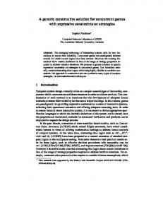
The placement algorithms (in an attempt to reduce path delays) gather in the same area the logic that is needed to implement the components of a given function. It is unwise to disperse it, since it would generate longer paths (and hence, an increase in path delays). On the other hand, it would also put too much stress upon the limited routing resources. Therefore, the relocation process should take place between neighbouring CLBs. If necessary, the relocation of a complete function may occur in several stages, to avoid an excessive increase in path delays during the relocation interval. 10. THE FPGA REARRANGEMENT AND PROGRAMMING TOOL To support the implementation of the test and management process, a tool based on the JBits software — a set of Java classes that provide an Application Programming Interface (API) to access the Xilinx FPGA bitstream [30] — was developed. With the user interface shown in figure 19, this tool produces the partial configuration files and carries out the partial and dynamic reconfiguration of the FPGA through the Boundary Scan interface.
Figure 19: Interface of the FPGA rearrangement and programming tool The partial configuration files that implement the rearrangements defined by the relocation procedure are generated automatically, greatly simplifying the task of the designer. The input information may be provided in the form of a complete configuration file (generated by the Xilinx design environment), or by providing the co-ordinates (source and
destination) of the CLB to be relocated. The tool also keeps a complete copy of the current configuration, enabling system recovery in case of failure. 11. CONCLUSION This paper proposed an active replication method that enables the reconfiguration of partial and dynamically reconfigurable FPGAs, without interfering with any function currently running. The proposed method enables: 1. the release for test of currently occupied resources, allowing the implementation of a truly online structural test of the FPGA, able to correct any errors that are caused by transient faults; 2. the online management of the FPGA resources, supporting the rearrangement of those functions that are currently running, defragmenting the logic space in order to facilitate the implementation of incoming functions (allowing a true implementation of the concept of virtual hardware). The tool that was developed to support the implementation of the relocation procedure enables the complete automation of the whole process and an optimised management of the available resources. Further work is under way to increase the functionality and flexibility of this tool. REFERENCES [1] X. P. Long, H. Amano, “WASMII: a Data Driven Computer on a Virtual Hardware”, Proc. of the 1st IEEE Workshop on FPGAs for Custom Computing Machines, 1993, pp. 33-42. [2] J. M. P. Cardoso, H. C. Neto, “An Enhanced Static-List Scheduling Algorithm for Temporal Partitioning onto RPUs”, Proc. of the 10th Intl. Conf. on VLSI, 1999, pp. 485-496. [3] R. Maestre, F. J. Kurdahi, R. Hermida, N. Bagherzadeh, H. Singh, “A Formal Approach to Context Scheduling for Multicontext Reconfigurable Architectures”, IEEE Trans. on VLSI Systems, Vol. 9, No. 1, Feb. 2001, pp. 173-185. [4] M. Sanchez-Elez, M. Fernandez, R. Maestre, R. Hermida, N. Bagherzadeh, F. J. Kurdahi, “A Complete Data Scheduler for Multi-Context Reconfigurable Architectures”, Proc. of the IEEE Intl. Conference on Design, Automation and Test in Europe, 2002, pp. 547-552. [5] N. R. Shnidman, H. Mangione-Smith, M. Potkonjak, “On-Line Fault Detection for Bus-Based Field Programmable Gate Arrays”, IEEE Trans. on VLSI Systems, Vol. 6, No. 4, pp. 656-666, December 1998. [6] F. Hanchek, S. Dutt, “Methodologies for Tolerating Cell and Interconnect Faults in FPGAs”, IEEE Trans. on Computers, Vol. 47, No. 1, pp. 15-33, Jan. 1998. [7] J. Lach, H. W. Mangione-Smith, M. Potkonjak, “Low Overhead Fault-Tolerant FPGA Systems”, IEEE Trans. on VLSI Systems, Vol. 6, No. 2, pp. 212-221, June 1998. [8] W. Huang, E. J. McCluskey, “A Memory Coherence Technique for Online Transient Error Recovery of FPGA Configurations”, Proc. of the 9th ACM Int. Symposium on Field-Programmable Gate Arrays, pp. 183-192, February 2001. [9] IEEE Standard Test Access Port and Boundary Scan Architecture (IEEE Std 1149.1), IEEE Std. Board, July, 2001, 208 p. ISBN 0-7381-2945-3. [10] C. Stroud., S. Konala, P. Chen, M. Abramovici, “Built-In Self-Test of Logic Blocks in FPGAs (Finally, A Free Lunch: BIST Without Overhead!)”, Proc. of the 14th IEEE VLSI Test Symposium, pp. 387-392, April 1996. [11] C. Stroud, E. Lee, M. Abramovici, “BIST-Based Diagnostic of FPGA Logic Blocks”, Proc. of the International Test Conference, pp. 539-547, Nov. 1997. [12] C. Stroud, S. Wijesuriya, C. Hamilton, M. Abramovici, “Built-In Self-Test of FPGA Interconnect”, Proc. of the International Test Conference, pp. 404-411, Nov. 1998. [13] A. Doumar, T. Ohmameuda, H. Ito, “Design of an automatic testing for FPGAs”, IEEE European Test Workshop Compendium of Papers, May 1999. [14] W. K. Huang, F. J. Meyer, X. Chen, F. Lombardi, “Testing Configurable LUT-Based FPGA's”, IEEE Trans. on VLSI Systems, Vol. 6, No. 2, pp. 276-283, June 1998. [15] W. K. Huang, F. J. Meyer, F. Lombardi, “An approach for detecting multiple faulty FPGA logic blocks”, IEEE Trans. on Computers, Vol. 49, No. 1, pp. 48-54, Jan. 2000.
[16] T. Inoue, S. Miyazaki, H. Fujiwara, “Universal Fault Diagnosis for Look-up Table FPGAs”, IEEE Design and Test of Computers, Vol. 15, No. 1, pp. 39-44, January-March 1998. [17] M. Renovell, J. M. Portal, J. Figueras, Y. Zorian, “RAM-Based FPGA's: A Test Approach for the Configurable Logic”, Proc. of the IEEE Int. Conference on Design, Automation and Test in Europe, pp. 82-88, February 1998. [18] M. Renovell, J. M. Portal, J. Figueras, Y. Zorian, “Testing the interconnect of RAM-based FPGAs”, IEEE Design and Test of Computers, Vol. 15, No. 1, pp. 45-50, January-March 1998. [19] M. Abramovici, C. Stroud, S. Wijesuriya, C. Hamilton, V. Verma, “On-Line Testing and Diagnosis of FPGAs with Roving STARs”, Proc. of the 5th IEEE Int. On-Line Testing Workshop, pp. 2-7, July 1999. [20] A. L. Burress, P. K. Lala, “On-Line Testable Logic Design for FPGA Implementation”, Proc. of the International Test Conference, pp. 471-478, November 1997. [21] M. Renovell, J. M. Portal, P. Faure, J. Figueras, Y. Zorian, “Test Generation Optimization for a FPGA Application-Oriented Test Procedure”, Proc. of the 15th Design of Circuits and Integrated Systems Conference, pp. 330-336, November 2000. [22] M. G. Gericota, G. R. Alves, M. L. Silva, J. M. Ferreira, “Active Replication: Towards a Truly SRAM-based FPGA On-Line Concurrent Testing”, Proc. of the 8th IEEE On-Line Testing Workshop, pp. 165-169, July 2002. [23] Politécnico di Torino ITC’99 benchmarks, available at http://www.cad.polito.it/tools/itc99.html [24] Manuel G. Gericota, Gustavo R. Alves, Miguel L. Silva, José M. Ferreira, “Run-Time Management of Logic Resources on Reconfigurable Systems”, Proc. of the IEEE Intl. Conference on Design, Automation and Test in Europe 2003, pp. 974-979, March 2003. [25] Manuel G. Gericota, Gustavo R. Alves, Miguel L. Silva, José M. Ferreira, “On-line Defragmentation for Run-Time Partially Reconfigurable FPGAs”, Proc. of the 12th International Conference on Field Programmable Logic and Applications : Reconfigurable Computing is Going Mainstream, pp. 302-311, September 2002, edited by Manfred Glesner, Peter Zipf and Michel Renovell. 1st edition, Berlim : Springer, 2002. Series: Lecture Notes in Computer Science 2438. ISBN 3-540-44108-5. [26] Manuel G. Gericota, Gustavo R. Alves, Miguel L. Silva, José M. Ferreira, “Programmable Logic Devices: A Test Approach for the Input/Output Blocks and Pad-to-Pin Interconnections”, 4th IEEE Latin-American Test Workshop Digest of Papers, pp. 72-77, February 2003. [27] O. Diessel, H. El Gindy, M. Middendorf, H. Schmeck, B. Schmidt, “Dynamic scheduling of tasks on partially reconfigurable FPGAs”, IEE Proc.-Computer Digital Technology, Vol. 147, No. 3, May 2000, pp. 181-188. [28] M. Vasilko, “DYNASTY: A Temporal Floorplanning Based CAD Framework for Dynamically Reconfigurable Logic Systems”, Proc. 9th Intl. Workshop on Field-Programmable Logic and Applications, 1999, pp.124-133. [29] M. Teich, S. Fekete, J. Schepers, “Compile-time optimization of dynamic hardware reconfigurations”, Proc. Intl. Conf. on Parallel and Distributed Processing Techniques and Applications, 1999, pp. 1097-1103. [30] S. A. Guccione, D. Levi, P. Sundararajan, “JBits Java based interface for reconfigurable computing”, Proc. 2nd Military and Aerospace Appl. of Prog. Devices and Technologies Conf., 1999.