Indonesian Journal of Electrical Engineering and Computer Science Vol. 5, No. 3, March 2017, pp. 656 ~ 660 DOI: 10.11591/ijeecs.v5.i3.pp656-660
656
Conductive and Inductive Coupling between Faulted Power Lines and Buried Pipeline by Considering the Effect of Soil Structure 1
2
3
4
Ali I. El Gayar , Zulkurnain Abdul-Malek* , Mohammed Imran M , Chin-Leong Wooi , 5 Ibtihal Fawzi Elshami 1,2,3,4,5
Institute of High Voltage and High Current, Faculty of Electrical Engineering, Universiti Teknologi Malaysia, 81310 Johor Bahru, Johor, Malaysia , telp +60-7-5535615, fax +60-7-5578150 1,5 College of Electrical and Electronics Technology-Benghazi-Libya *Corresponding author, e-mail:
[email protected]
Abstract The AC total interference of faulted power lines to gas pipelines sharing the same right of way, which may pose a threat to operating personnel and equipment, was studied. The main advantage of this work is to determine the effects of different soil structures on the induced voltage for various soil resistivities. Two main approaches were used to compute the induced voltages, namely the method of moment (MOM), which is based on electromagnetic field theory, and the circuit based method, which uses the circuit grounding analysis to compute the conductive interference and the circuit based models to compute the inductive interference. A 10-km-long parallel pipeline-transmission line model was developed. The soil resistivity was varied, and the induced voltages obtained from both approaches were compared. Soil resistivity and soil structure are important parameters that affect the AC interference level. The results of the study show that the earth potentials and the metal GPRS are independent. Higher soil resistivity causes the tower ground resistance to increase, thus making the shield wire’s attractiveness as a fault current return path to increase, which in turn forces the induced net EMF and the cumulative GPR in the pipeline to reduce. Keywords: AC interference, Gas pipeline, Transmission line, Inductive and conductive, Non-uniform soil Copyright © 2017 Institute of Advanced Engineering and Science. All rights reserved.
1. Introduction Damage of high voltage equipment and electrical shocks to personnels due to lightning and fault currents are still a major concern. The protection of high voltage equipment from lightning related damages had been extensively studied. Many studies on lightning related topics such as lightning characteristics [1-10] show the importance of providing sufficient protection from the damages it can potentially cause. Many work had also been published to improve lightning surge protection [11, 12] and monitoring of lightning protection devices using various techniques [8], [13-18]. Suitable earthing designs are also vital to ensure safe level of potential rise in the event of lightning strikes on various systems such as transmission lines [19-21]. Phase to ground fault current is dispersed into the earth through the tower and soil structure. This current may induce voltages in a metallic structure, such as a pipeline, located nearby the faulted transmission line (TL). The magnitude of induced voltage is dependent on many factors such as soil structure, soil resistivity, distance between the TL and the metallic structure, current, and earth electrode dimensions. The soil structure effect itself is influenced by several parameters, namely, soil resistivity, number of horizontal layers, number of vertical layers, and thickness of each soil layer [20]. The pipeline or any metallic structure near a faulted TL absorbs part of the energy due to the AC total interference which consists of conductive and inductive couplings. The capacitive coupling maybe neglected for buried pipelines. The AC total interference may result in electrical hazard for people touching or standing near the exposed lines and any connected metallic structure. Furthermore, extreme stress voltages across the pipeline coating can result in the infraction of pipeline coating, leading to the pipeline corrosion as well as degradation of the insulating edge and the pipeline cathodic Received November 30, 2016; Revised February 3, 2017; Accepted February 21, 2017
IJEECS
ISSN: 2502-4752
657
protection. The Current Distribution Electromagnetic interference Grounding and Soil structure analysis software (CDEGS) which was based on the method of moment (MOM), was used to study the AC total interference between high voltage transmission lines and pipelines.
2. Research Method A specific configuration illustrated in Figure 1 considers the complete electromagnetic interference network. The model consists of 115 kV three phase overhead transmission line (OHTL) with single shield wire. Two substations at the end terminals feed the OHTL with 830 A current under normal operation. The power line total length is 30 km and it shares a common 10-km corridor with a 24” gas pipeline. The pipeline is located at the center of the right-of-way and is 50 m away from the center of the power line. The pipeline changes its direction perpendicularly at each end and continues for 1000 m before being terminated. The outer pipe diameter and wall thickness are 0.610 m and 0.9527 cm, respectively. The pipe is buried at a depth of 1 m. The pipe type is 24” STD and is made of steel. It has a resistivity of 10 p.u. (with respect to anneal copper) and permeability of 300 p.u. (with respect to free space). The pipeline coating resistivity and thickness are 40,898,000 ohm-m and 1 mm, respectively when new (no defective in coating).
Figure 1. Top view of the modeled transmission line and pipeline system showing the relevant cross section of the common corridor
Figure 2. Cross-section of 115 kV OHTL tower Conductive and Inductive Coupling between Faulted Power Lines and Buried… (Ali I. El Gayar)
658
ISSN: 2502-4752
The average span length of the OHTL is 200 m. The 477 ACSS type conductors with a radius of 1.074 cm were used. The permeability and resistivity of the conductor were set at 1 p.u and 1.6 p.u, respectively. The location of the phase conductors are 24 m, 22.5 m and 21 m above the ground as shown in Figure 2. The shield wire has inner and outer radii of 0.255 cm and 0.771 cm, respectively. It was located at 27 m above the ground. The OHTL tower grounding is accomplished using a 6.1 m single grounding rod. The tower footing grounding resistance was calculated based on corresponding soil resistivity value. For the default soil resistivity of 100 ohm-m, the tower grounding resistance is 10.7 ohm. To demonstrate the multilayer soil effects of total AC interference under local fault conditions (midway of the corridor), various computer simulations were made; corresponding to two soil layer structure. The effects of conductive and inductive interference were taken into consideration, since the fault occurred inside the parallel exposure. The transmission-line system of Figure 1 and 2 has been investigated for several different soil structures.
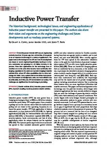
3. Results and Analysis Initially, the case of two horizontal layers was examined. The first layer had a resistivity ranging from 100 to 1000 Ω-m, while its thickness t1 varied from 10 to 1000 m. The second layer’s thickness t2 was infinite in depth. Figure 3 and 4 illustrate the induced voltage in the middle of the pipeline versus the thickness of the first layer. As shown in the first graph, the resistivity of the first layer had a constant value of ρ 1=100 Ω-m, with the resistivity of the second layer having values of ρ2=200, 500, and 1000 Ω-m. The opposite condition is shown in the second graph, so, the second layer was kept constant at value of ρ2=100 Ω-m and the resistivity of the first layer varied. In both graphs, the straight horizontal lines represent the cases of uniform earth having resistivity of 100, 300, 500, and 1000 Ω-m, respectively.
Figure 3. Induced voltage at the middle of pipeline, in case of first layer is constant, versus thickness of the first earth layer, as a function of the soil resistivity of the second earth layer. A single phase to ground fault was assumed in the nearby power line
It is clearly shown in Figure 3, when the thickness of first layer reached 600 m and above, the AC total interference level could be determined, with insignificant error, without taking into account the presence of the second layer. On the other hand, when the thickness of the first layer was small and the difference between the resistivity of the two layers was large, a significant error could be obtained, as expected. For instance, when the soil resistivity of two layers were ρ1=100 Ω-m and ρ2=1000 Ω-m, respectively, the thickness of the first layer was only 10 m, and there was an error of around 22% from the value calculated, by having a uniform soil resistivity of 100 Ω-m. Therefore, resistivity measurements should be made at adequate depths, in order to calculate the AC total interference with minimum error.
IJEECS Vol. 5, No. 3, March 2017 : 656 – 660
IJEECS
ISSN: 2502-4752
659
Figure 4. Induced voltage at the middle of pipeline, in case of second layer is constant, versus the thickness of the first earth layer, as a function of the resistivity of the second earth layers. A single phase-to-ground fault was assumed in the nearby power line.
The difference between results in Figure 3 and 4 is that, in Figure 4, the effect of the existence of the second layer continued until the first layer thickness reached 1500m. From Figure 4, it could be generalized that, if the first layer exceeded an approximately 1500-m thickness, the total interference could be determined with insignificant error, without taking into account the presence of the second layer. The error reached the maximum of 25%, when the thickness of first layer was small (10 m), and the difference between the resistivity of the two layers was large.
4. Conclusion Based on the MOM and the circuit based methods used for the determination of the inductive and conductive interference between a power line and a neighboring pipeline, the influence of the soil structure on conductive and inductive interference levels has been demonstrated. Cases of two horizontal soil layers are investigated in the paper. Resistivity measurements at adequate depths should be made if an accurate calculation of the induced parameters on the pipeline is needed. Moreover, the importance of measuring the soil resistivity at locations up to several hundred meters away from the rights-of-way has been illustrated. Situations when a multilayer soil may be replaced with an equivalent homogeneous earth soil have also been discussed concerning inductive interference predictions. These approximations may be useful for the design of effective mitigation systems, with minimum computational effort and less soil resistivity measurements.
References [1]
[2] [3] [4]
[5] [6]
NA Ahmad, M Fernando, ZA Baharudin, V Cooray, H Ahmad, ZA Malek. Characteristics of narrow bipolar pulses observed in Malaysia. Journal of Atmospheric and Solar-Terrestrial Physics. 2010; 72: 534-540. B Salimi, K Mehranzamir, Z Abdul-Malek. Statistical analysis of lightning electric field measured under Malaysian condition. Asia-Pacific Journal of Atmospheric Sciences. 2014; 50: 133-137. S Vahabi-Mashak, Z Abdul-Malek, K Mehranzamir, H Nabipour-Afrouzi, B Salimi, CL Wooi. Modeling of Time of Arrival Method for Lightning Locating Systems. Advances in Meteorology. 2015. CL Wooi, Z Abdul-Malek, B Salimi, NA Ahmad, K Mehranzamir, S Vahabi-Mashak. A Comparative Study on the Positive Lightning Return Stroke Electric Fields in Different Meteorological Conditions. Advances in Meteorolog. 2015. B Salimi, Z Abdul-Malek, K Mehranzamir, SV Mashak, HN Afrouzi. Localised single-station lightning detection by using TOA method. Jurnal Teknologi. 2013; 64. K Mehranzamir, Z Abdul-Malek, B Salimi, NA Ahmad. Return Strokes Measurements of Electric Field Produced by Lightning Discharges in Malaysia. Applied Mechanics & Materials. 2014.
Conductive and Inductive Coupling between Faulted Power Lines and Buried… (Ali I. El Gayar)
660 [7] [8] [9]
[10]
[11] [12] [13] [14] [15]
[16]
[17] [18] [19]
[20]
[21]
ISSN: 2502-4752
K Mehranzamir, Z Abdul-Malek, B Salimi, NA Ahmad. Observation of Isolated Breakdown Lightning Flashes in a Tropical Region. Applied Mechanics & Materials. 2014. B Salimi, Z Abdul-Malek, K Mehranzamir, NA Ahmad. Study on the Vertical Component of Lightning Electric Field During Monsoon Period in Malaysia. Applied Mechanics & Materials. 2014. CL Wooi, Z Abdul-Malek, NA Ahmad, M Mokhtari, B Salimi. Statistical Analysis on Preliminary Breakdown Pulses of Positive Cloud-to-Ground Lightning in Malaysia. International Journal of Electrical and Computer Engineering (IJECE). 2016; 6: 844-850. CL Wooi, Z Abdul-Malek, NA Ahmad, AI El Gayar. Statistical analysis of electric field parameters for negative lightning in Malaysia. Journal of Atmospheric and Solar-Terrestrial Physics. 2016; 146: 6980. A Haddad, D German, RT Waters, Z Abdul-Malek. Co-ordination of spark-gap protection with zincoxide surge arresters. IEE Proceedings-Generation, Transmission and Distribution. 2001; 148: 21-28. A Haddad, RT Waters, D German, Z Abdul-Malek. Current disparity in multi-column surge arresters. IEE Proceedings-Generation, Transmission and Distribution. 2005; 152: 945-951. C Wooi, Z Abdul-Malek, SV Mashak. Effect of Ambient Temperature on Leakage Current of Gapless Metal Oxide Surge Arrester. Jurnal Teknologi. 2013; 64. N Novizon, ZA Malek, N Bashir, N Asilah. Thermal Image and Leakage Current Diagnostic as a Tool for Testing and Condition Monitoring of ZnO Surge Arrester. Jurnal Teknologi. 2013; 64. Z Abdul-Malek, AH Khavari, H. Nabipour-Afrouzi, and S. Vahabi-Mashak. Effect of Ambient Temperature Zinc Oxide Surge Arrester Condition Monitoring. Applied Mechanics and Materials. 2014; 554: 573. Z Abdul-Malek. Correlation between Third Harmonic Leakage Current and Thermography Image of Zinc Oxide Surge Arrester for Fault Monitoring Using Artificial Neural Network. Applied Mechanics & Materials. 2014. VM Saeed, Z Abdul-Malek, NA Hadi, CL Wooi, AH Khavari. Surge Arrester Leakage Current Analysis by Using Particle Swarm Optimization Technique. Applied Mechanics and Materials. 2014: 608-612. CL Wooi, Z Abdul-Malek, SV Mashak. Implementation of Wireless Thermal Camera Remote Control System. Applied Mechanics and Materials. 2014; 554: 561. D Caulker, H Ahmad, Z Abdul-Malek. Evaluation of Lightning Performance of Overhead Transmission Line Based on 132 kV Double Circuit Tower Structures. International Review on Modelling and Simulations. 2010; 3. AI El Gayar, Z Abdul-Malek. AC interference on gas pipelines due to phase to ground faults in overhead transmission lines. International Journal of Electrical and Computer Engineering. 2016; 6: 1363-1370. AI El Gayar, Z Abdul-Malek. Induced voltages on a gas pipeline due to lightning strikes on nearby overhead transmission line. International Journal of Electrical and Computer Engineering. 2016; 6: 495-503.
IJEECS Vol. 5, No. 3, March 2017 : 656 – 660