This is done by having controls in place that ensure consistent software via the creation of a baseline product. ⢠Status Accounting. Records and reports the ...
Configuration Management Concept for Lyee Software ¨ Volker GRUHN, Raschid IJIOUI, Dirk PETERS, Clemens SCHAFER Fachbereich Informatik Lehrstuhl 10, Universit¨at Dortmund, D-44221 Dortmund, Germany
Abstract. A configuration management concept is presented for software projects using Lyee methodology. To show this concept an introduction in configuration management is given. Then, the structure of Lyee programs is redefined by sets and their dependencies. From this redefined structure, the actual configuration management concept is derivated and discussed.
1
Introduction
Software configuration management has been defined as the discipline of controlling the evolution of complex software systems [12]. As a vital task for professional software development, it also has to be provided for software projects carried out using Lyee methodology. In this paper we discuss a software configuration management concept for Lyee. First, we give a short introduction into configuration management in general and software configuration management in particular. Additionally, we describe an already existing software configuration management testbed as base for our implementation. Then, we re-define the structure of Lyee programs using mathematical definitions, in order to provide a sound basis for further discussions. These definitions make it possible to map the entities of Lyee programs onto configuration items introduced before. Next, we depict the architecture of a system using the testbed. Finally, we discuss the concept and how its realization and evaluation will take place. 2
Configuration Management and Software Configuration Management
2.1
Configuration Management
A standard definition of configuration management can be found at [7, 8, 4]. It describes the following configuration management procedures: • Identification. Reflects the structure of the product, identifies components and their type, making them unique and accessible in some form1 . 1 The
IEEE software configuration management standards [7, 8] denote components by configuration items; the synonyms configuration object or simply object are also found.
• Control. Controls the release of a product and the changes to it throughout its life cycle. This is done by having controls in place that ensure consistent software via the creation of a baseline product. • Status Accounting. Records and reports the status of components and change requests, and gathers vital statistics about components in the product. • Audit and Review. Validates the completeness of a product and maintains consistency among the components, ensuring that the product is a well-defined collection of components. Further surveys on software configuration management [4] extend this definition to include procedures like construction management, process management, and team work control: • Manufacture. Manages the construction and building of the product in an optimal manner. • Process Management. Ensures the carrying out of the organization’s procedures, policies and life cycle model. • Team Work. Controls the work and interactions between multiple developers. 2.2
Software Configuration Management
In [5] an approach to classify software configuration management functionality is made. According to this examination the following two major software configuration management approaches can be identified: 2 • Checkin/Checkout Model. The basic software configuration management model introduces the concept of a repository holding multiple versions of a product component. Developers can copy versions from (check out) and to (check in) the repository. • Change-Oriented Model. As its name says, the change-oriented model focuses on changes rather than on versions. In this model, versions are the product of change set applied to a baseline. This model is useful for propagating and combining changes across users and sites. To discuss the software configuration management concept for Lyee properly we introduce some more definitions to make the key role players in the software configuration management game explicit (cited from [2]): • A (software) object (item) is any kind of identifiable entity put under software configuration management control. An object may be either atomic, i.e. it is not decomposed any further (internals are irrelevant to software configuration management), or composite. A composite object is related to its components by composition relationships. Furthermore there may be dependency relationships between dependant and master objects. 2 In
[5] the Composition Model and the Long Transaction Model are also mentioned. These two are left out here due to their minor relevance.
windows
source
a.c
b.c
text
includes
c.h
d.h
source
e.c
f.c
g.c
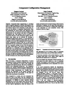
Figure 1: Sample NUCM Repository
• A version is an implicit or explicit instance of a versioned object which groups “similar” objects sharing same properties. We distinguish between revisions (historical versioning) and variants (parallel versions). • A configuration is a consistent and complete version of a composite object, i.e. a set of component versions and their relationships. A configurations is called bound if it exclusively contains versions as its components. Coversively, an unbound configuration exclusively consists of versioned objects. A partly bound configuration lies in between. According to [3] a last definition has to be set up: • A delta is the difference between two versions and serves to identify the changes and to save space in the repository. 3
The NUCM System
Many research activities have been performed on the topic of software configuration management. Thus, many configuration management tools have evolved from these efforts. For this reason we tried to find an existing software configuration management tool that is suitable for our software configuration management concept for Lyee software. After the comparison of different software configuration management systems 3 where we examined their flexibility, the availablity of source code, and the suitability for being adapted we came to the conclusion to use the Network-Unified Configuration Management (NUCM) introduced in [6]. NUCMs storage model allows the user to store and to version artifacts. Artifacts refer to the software objects mentioned above. As for software objects, artifacts can be atomic or composite. Atomic software objects are called atoms within NUCM. Composite software objects are called collections within the terminology of NUCM. 3 In
particular, we compared the Unified Software Versioning Model (USVM, see [14]), the Uniform Version Model (UVM, see [13]), the Concurrent Versions System (CVS, see [1]), the Resource Control System (RCS, see [11]) and NUCM.
An atom can be shared among mutliple collections. Collections can be used recursively; they can be part of or larger, higher-level collections. A repository consists of one or more top-level collections which serve as the entry points to the contents of the repository. Figure 1 presents an example to illustrate the basic concepts of NUCM (see [6]). The figure shows a portion of a repository for the C code of a hypothetical software. However, NUCM is not restricted to C code software. This example has been chosen to show the storage of dependent objects in the NUCM storage. Collections are shown as ovals, atoms as rectangles. Containment relationships are indicated as arrows. Two top level collections, windows and text contain separate collections called source and a shared collection called includes. Both the collections source and includes only contain atoms that are files in this example. Versioning is indicated by the use of shades. A darker shade represents an older version of an artifact. Dashed lines indicate containment relationships for older versions of collections. For example, the older version of collection includes contains an older version of atom c.h. Both the older and newer versions contain the same version of atom d.h. NUCM provides functions that allow the creation of views of repository contents. That means, the contents of the repository are extracted to a file system. This file system will have the same structure as the data in the repository. Other functions that read the contents of a file system and store the data in the repository are provided as well. 4
Static Structure of Lyee Software
The definitions of the key role players of a software configuration management system depicted above introduced entites as software objects or composition relationships. For setting up a software configuration management concept for Lyee, the elements of Lyee programs need to be mapped onto these configuration items. This implies, that the relationships between the Lyee program items are clearly defined. One problem we were faced with is the fact that it is hard to get a formal view of the structure of Lyee software from other publications. Thus, we decided to generate mathematical definitions to illustrate the relations between the entities of Lyee software. For these considerations we modeled the parts of Lyee programs that are of structural interest. The aim of these definitions is to capture the static structure of Lyee programs. It is not intended to provide a dynamic model that could represent a Lyee program at runtime. The definitions have been derived from the description of the Lyee structure in [9, 10] and from the study of the database structure of the LyeeALL tool in combination with information from the Institute of Computer Based Software Methodology and Technology, Tokyo. The study of the database structure of the LyeeALL tool enhanced our understanding of the Lyee program structure and inspired the definitions below. As we tried to emphasize the parts of Lyee structures that are of structural relevance for our software configuration management purpose, the definitions are incomplete to a certain extent: in all cases there are additional attributes. We left out these attributes to keep the definitions simple. This is possible as the attributes are not necessary for the understanding of the program structure. All these attributes have been subsumed in the Xν that can be found in the definitions.We begin with the topmost entity that can be found, the project.
Definition 1 (Project) A Lyee project is a tuple j = (nj , S, Xj ) consisting of the name of the project nj and a set of systems S = {s1 , ..., sx } with x ∈ N. Regarding the information gathered from the examination of the LyeeALL tool, a project can be decomposed into one or multiple systems. Definition 2 (System) A Lyee system is a tuple s = (ns , D, F, Xs ) with ns as the name of the system. D = {d1 , ..., dx } is a set of process route diagrams, F = {f1 , ..., fy } is a set of defineds with x, y ∈ N. The process route diagrams in the system are discussed later. We continue with the definition of the defineds. Definition 3 (Defined) A defined in terms of Lyee theory can be specified as a tuple f = (nf , tf , Xf ), where nf is the name of the defined, tf is the type of the defined. Typically, the type of the defined tf will be one of {screen, database, ...}. A defined refers to entities as database tables or dialog windows. The names of these entities will be reflected by nf . Xf stands for additional technical information that has to be stored software configuration management system but that has no structural information in it. The type of the defined tf was left separate in the definition as for configuration management purposes this type indicates which additional data not covered by the LyeeALL tool has to be processed. For example, in case of tf = screen the definition of the related dialog window has to be put under software configuration management control, too. We continue with the definition of the items in a defined. Definition 4 (Item in Defined) An item in a defined can be specified as tuple i = (ni , f , Xi ) where ni is the name of the item in the defined, f the defined. The items of a defined are e.g. field names within a database table or dialog fields within a dialog window. As mentioned above, the second major element of systems besides the defineds are the process route diagrams. We continue with their definition. Definition 5 (Process Route Diagram) A process route diagram is defined as tuple d = (nd , B, b0 , p0 , Xd ) where nd is the name of the process route diagram. B = {b1 , ..., bx }, x ∈ N is a set of base structures. b0 ∈ B is an initial base structure, p0 an initial pallet. Closely related to the definition of the process route diagram is the base structure. Definition 6 (Base Structure) A base structure is a tuple b = (nb , bp , p4 , p2 , p3 , Xb ) where nb is the name of the base structure, bp is the parent base structure. p4 , p2 and p3 are pallets. If a base structure has no parent, we write bp = ∅. Here as well, additional information as e.g. the interaction type can be subsumed in Xb . If we continue with the refinement of our definitions, we have to define the pallets.
Definition 7 (Pallet) A pallet is a tuple p = (np , L, R, Xp ) consisting of a set of logical units L = {l1 , ..., lx } and a set of routing vectors R = {r1 , ..., ry } with x, y ∈ N. np is the name of the pallet. The next items to be defined are the logical units. Definition 8 (Logical Unit) A logical unit is a tuple l = (nl , f , tl , S, A, Xl ) where nl is the name of the logical unit. tl ∈ {input, output} is the type of the logical unit. f is the defined the logical unit is assigned to. S = {s1 , ..., sx } is a set of signification vectors, A = {a1 , ..., ay } is a set of action vectors with x, y ∈ N. The logical units lead to the definitions of the signification vectors and the action vectors. Definition 9 (Signification Vector) A signification vector in terms of Lyee methodology is a tuple vs = (nvs , w, Wdom , Q, Xvs ). nvs is the name of the signification vector. w is the word that is calculated by the signification vector. Q is a set of functions that are executed to calculate w. This refers to the contents of the up to seven boxes of a signification vector. Let ϕ be the second element of Q so that ϕ represents the program code stored in the second box of the signification vector. Wdom are all words in the domain of ϕ, this means all words that are necessary to execute ϕ. When signification is established according to Lyee terminology, ϕ(Wdom ) is calculated and the result is stored in the word w.
Definition 10 (Action Vector) An action vector is a tuple va = (nva , w, l, tva , Q, Xva ) with a word w and a logical unit l. nva is the name of the action vector. Q contains the contents of the seven boxes and thus represents the requirements in Lyee terminiology. tva ∈ {input, output, structural} is the type of the action vector. This definition of the action vector captures the input vectors, the output vectors and the structural vectors in terms of Lyee methodology. The remaining vector type not covered yet is the routing vector. We define: Definition 11 (Routing Vector) A routing vector is a tuple vr = (nvr , w, tvr , p, Xvr ) with the name of the vector nvr , the word w, the type tvr ∈ {duplex, continuous, multiplex, recursive}, and the pallet p. Although the type of the routing vector has no implications on the static structure of the routing vector within the Lyee program and thus could be subsumed in the Xvr , we modeled this information separately in the tvr . This is due to the reason that the type of routing has implications on the structure of the software as whole and has to be regarded when a component oriented view on Lyee software is established. Definition 12 (Word) A word in terms of Lyee theory is a tuple w = (nw , X) with nw as the name of the word.
Words are used by different vectors. Due to the definition of these vectors, words are always related to a pallet. Words can also be related to a logical unit, which is not necessary. This leads to the consequence that one word representing a certain data entity will be reflected by multiple words of the type defined here. However, these multiple words will have the same name, the same logical unit but differ in the pallet. Definition 13 (Boundary Word) A boundary word in terms of Lyee theory is a tuple wb = (nwb , w, Xwb ) with nwb as the name of the boundary word and the word w. The boundary word wb can be regarded as a reference to the word w.
The definition of the boundary word is shown here for completeness. With these definitions we redefined the static structure of Lyee programs in a way to formulate the actual configuration management concept. 5
Lyee Configuration Management Concept
The configuration management concept for Lyee software can be split up into two tasks: first, a mapping has to be defined that associates the elements of the static structure of Lyee programs with software objects in the NUCM system. Then, the operations to put a Lyee program under software configuration management control or to retrieve a version of the program from the repository have to be specified. 5.1
Mapping the Lyee Program Structure onto Software Objects
Based on the definitions of the Lyee program structure, the following mapping rules can be set up: • A tuple always becomes a collection in the NUCM repository. • Any item of a tuple in a definition that is neither a set nor a tuple will become an atom in the NUCM repository. • Any Xν in a definition will become a collection in the NUCM repository. In this collection, all items forming the Xν will become atoms. • All sets within tuples become collections in the NUCM repository. Figure 2 shows the NUCM notation of a pallet and a logical unit. The tuple of the pallet is transformed into the top-level collection p. Its element correspond to the definition of the pallet p = (np , L, R, Xp ): the name np is stored as atom. L is the set of logical units and thus stored as collection. According to the rules, The set of routing vectors R and Xp are stored as collection, too. L consists of three logical units {l1 , l2 , l3 } in this example. The refinement is shown for l2 . The elements of the collection l2 are set up according to the definition of the logical unit l = (nl , f , tl , S, A, Xl ). The name nl and the type tl are stored as atoms, the defined f , the sets S and A, and the additional data Xf are stored as collections. Note that the elements of some collections are not drawn in this example.
p
l1
nl
R
L
np
l2
f
Xp
l3
S
tl
A
Xl
Figure 2: Pallet and Logical Unit as NUCM Artifacts LyeeALL Database
Transformation
SCM Repository
Checkin
Software Objects
LyeeALL Database
Checkout
Re-Transformation
Software Objects
Figure 3: SCM Information Flow
5.2 Configuration Management Structure With the rules set up in the previous section it is possible to transform any Lyee project in a way that it can be put under the control of a NUCM system. In detail, the following steps are necessary to achive this goal. First, we concentrate on moving information into the configuration management system. This can be the creation of a new repository when a project is put under configuration management control the first time or it can be the update of the repository contents after changes have been applied to the program. Two steps are to be performed: • Transformation. This initial step scans the LyeeALL database and the additional files used by the LyeeALL tool to store the data of the Lyee project. This also includes additional files as e.g. the dialog screen definition files. After scanning, the transformation groups the gathered information together according to the definitions of the Lyee program structure. Then, the data will be written to a file system that acts as workspace for the NUCM system. • Checkin. During this step the NUCM system performs its built-in checkin operation. So the contents of the workspace are stored in the NUCM repository.
Other steps are required to retrieve the data from the repository. To get a working copy from the SCM repository into the LyeeALL database, a reverse process takes place: • Checkout. First, the data from the repository has to be checked out into a file system. The data stored in this file system will have the well-defined structure based on the definitions of the Lyee program structure. • Re-Transformation. Then, the re-transformation can scan the file system and store the data in the LyeeALL database or create additional files for the LyeeALL tool. As mentioned at the beginning of this paper, there are two major approaches for software configuration management: the state-based approach, realized in the checkin/checkout model, and the change-based approach, realized in the change-oriented model. Generally speaking, state based configuration management systems store differences between two versions of a component in a repository, change-based configuration managmenet systems are generalizations of conditional compiling. One characteristic of Lyee programs is that they do neither consist of multiple source files nor does the LyeeALL tool provide a functionality similar to conditional compiling. This leads to monolithic applications; it is almost impossible e.g. to build different variants of an existing program. To enhance the flexibility of Lyee programs it is possible to provide a configuration management system offering both, the state-based approach as well as the change-based approach. In [6] it is described how the NUCM system can be used to build a state-based or a changebased configuration management tool. One aspect of state-based configuration management is that a system can allow to check out one or multiple writeable copies of a software object. This rises the need for a merge operation that ensures consistency when these files are checked back into the system. Using one of the merging approaches mentioned in [14], it is possible to extend the Checkin-step of our proposed system to provide this functionality for Lyee software projects as well. 6
Discussion and Further Work
In section 4 we formulated definitions to represent the structure of Lyee programs. However, these definitions are generalizations of the structure that can be found in Lyee software. They can represent every Lyee program, but not every constuct composed using the definitions would be a valid Lyee program (despite the fact that this is impossible due to the ambiguity of the Xν ). One example: in Lyee programs, the initial pallet of a base structure is always a W04 pallet, thus ∀d ∈ D : w0 ∈ W04 with d(3) = w0 . Our definition does not necessarily require this. However, the structural restriction of Lyee programs is no problem for our system. The definitions provide another benefit than formulating a configuration management concept. Based on the definitions it is possible to set up propositions that indicate whether configurations of Lyee software can be made or how a larger project should be split up into parts and how they depend on each other. An example: assume that we have to process route diagrams p1 and p2 in a program. Using the definitions, the defineds ‘used’ by a process route diagram can be expressed as set. Let d1 be the set of defineds used in p1 , d2 the set of defineds used in p2 . Now we can suggest
that splitting the program into two configurations e.g. to establish team work will cause no problems if the intersection of the defineds used by the p1 and the defined used by p2 is the empty set. In other words: p1 and p2 can be developed by different persons, if d1 ∩ d2 = ∅. Please note that the intersection will not be empty if p1 and p2 refer to e.g. the same database. In this case, splitting can make sense as well, if the data base structure is left untouched. These considerations show how it is possible to introduce a component-oriented view on Lyee software. In our opinion, this is vital for Lyee methodology. If larger systems are to be developed using Lyee methodology, the possibility of cutting software into handsome parts has to exist. Furthermore, software configuration management only can make sense if there is a component oriented approach in the design paradigm. The software configuration management concept we described above introduces a second storage of the contents of the LyeeALL database. We chose to duplicate the data in this way as it offers the rather simple possibility to create the software configuration management system as stand-alone part that can be used in combination with the LyeeALL tool. For use in real software production it would be suitable to integrate the software configuration management system into the LyeeALL tool or the LyeeMAX tool. As mentioned, we can provide a software configuration management system that offers state-based versioning as well as change-based versioning. As we cannot judge at which approach is the best to use as our knowledge about the Lyee software process is still limited, we decided to realize these multiple approaches within the prototype of the system. The implementation of the prototype of the system is the next part of work that has to be performed. This prototype will cooperate with the LyeeALL tool and be restricted to the use of Visual Basic as target language for the Lyee programs. This makes implementation easier and does not limitate the universality of the validation results. After building the prototype we will conduct several steps to validate this concept. We will use the building of a partner component for insurances to test the versioning features of our configuration management concept. Additionally, we will introduce variants into this component to especially test the change-based versioning functions. 7
Conclusion
We have redefined the program structure of Lyee software using sets and their relationships. Using these definitions, we were able to formulate a configuration management concept for Lyee software that covers state-based versioning as well as change-based versioning. The evaluation of the system will be performed next to validate the results in this paper. In parallel to the evaluation we will continue to set up rules how larger Lyee projects can be split up to achive a maximum of independency for the sub-projects. Using this configuration management concept, the software process using Lyee methodology will get another toolkit meeting the needs of large-scale system development. References [1] B. Berliner. CVS II: Parallelizing Software Development. In Proceedings of the USENIX Winter 1990 Technical Conference, pages 341–352, Berkeley, CA, 1990. USENIX Association. [2] R. Conradi and B. Westfechtel. Configuring Versioned Software Products. In I. Sommerville, editor, Software Configuration Management: ICSE’96 SCM-6 Workshop, LNCS 1167, pages 88–109, Berlin, Germany, March 1996. Springer-Verlag.
[3] R. Conradi and B. Westfechtel. Towards a Uniform Version Model for Software Configuration Management. In R. Conradi, editor, Software Configuration Management: ICSE’97 SCM-7 Workshop, LNCS 1235, pages 1–17, Boston, Massachusetts, May 1997. Springer-Verlag. [4] S. Dart. Concepts in configuration management systems. In P. H. Feiler, editor, Proceedings 3rd International Workshop on Software Configuration Management, pages 1–18, Trondheim, Norway, June 1991. [5] P. H. Feiler. Configuration Management Models in Commercial Environments. Technical Report CMU/SEI-91-TR-7, Software Engineering Institute, Carnegie Mellon University, Pittsburgh, PA, March 1991. [6] A. van der Hoek, D. Heimbigner, and A. L. Wolf. A Generic, Peer-to-Peer Repository for Distributed Configuration Management. In International Conference on Software Engineering, pages 308–317, 1996. [7] The Institute of Electrical and Electronics Engineers, New York. IEEE Guide to Software Configuration Management, 1988. ANSI/IEEE Standard 1042–1987. [8] The Institute of Electrical and Electronics Engineers, New York. IEEE Guide to Software Configuration Management Plans, 1990. ANSI/IEEE Standard 828–1990. [9] F. Negoro. Principle of Lyee Software. Proceedings of the International Conference on Information Society in the 21st Century, 2000. [10] F. Negoro. The Predicate Structure to Represent the Intention for Software. In Proceedings of the International Conference on Software Engineering, Artificial Intelligence, Networking and Parallel/Distributed Computing, 2001. [11] W. F. Tichy. RCS - A System for Version Control. Software - Practice and Experience, 15(7):637–654, July 1985. [12] W. F. Tichy. Tools for software configuration management. In J. F. H. Winkler, editor, Proceedings of the International Workshop on Software Version and Configuration Control, pages 1–20, Grassau, Germany, 1988. Teubner Verlag. [13] B. Westfechtel, B. P. Munch, and R. Conradi. A layered architecture for uniform version management. IEEE Transactions on Software Engineering, 27(12):1111–1133, December 2001. [14] A. Zeller. Configuration Management with Version Sets. PhD thesis, University of Braunschweig, 1997.