Conflict detection and resolution for semi-autonomous vessels 1
E. Theunissen1 en C.A. de Groot2
Netherlands Defence Academy, the Netherlands,
[email protected] Netherlands Defence Academy, the Netherlands,
[email protected]
2
Abstract: A concept of operation for an autonomously navigating unmanned vessel is assumed which still involves a human operator at the decision making level for functions aimed at maintaining safe separation with other traffic. To minimize the occurrence of situations in which collision avoidance manoeuvres must be performed, the operator must be timely aware of potentially conflicting traffic situations. Conflict detection is typically performed by testing whether the current course and speed will result in a future situation in which ownship is no longer ‘well clear’. Resolution is achieved by determining and executing a manoeuvre that will keep ownship well clear. To support the operator with automated conflict detection and resolution functions, ‘well clear’ has to be objectively defined and quantified. Options to be considered are the contours of the ship domain or a spatial/temporal separation criterion. This paper discusses how ‘well clear’ is related to the ship domain, identifies limitations of a spatial-only definition for well clear and illustrates how the addition of a temporal separation threshold compensates for these limitations.
BIOGRAPHIES Erik Theunissen has been active in the area of electronic navigation systems since 1991. He holds an M.Sc. in Aerospace Engineering and an M.Sc. and PhD in Electrical Engineering. He is the author of over 130 papers on the topics of airspace integration, enhanced and synthetic vision systems, airport surface navigation, display design and unmanned systems. Cees de Groot is currently working as an assistant professor at the Netherlands Defence Academy, location Den Helder. His interest and his theoretical and practical knowledge and experience lie in the field of maritime navigation. Apart from lecturing, he is a participant in NLDA navigation research projects.
1
INTRODUCTION
The introduction of unmanned ships raises the question how the COLREGS should be interpreted. Opinions vary significantly, and an excellent overview of the issues is provided in (Allen, 2012). It is for example indicated that if an autonomous unmanned vessel would be regarded as “a vessel which from the nature of her work is restricted in her ability to manoeuvre as required by these Rules and is therefore unable to keep out of the way of another vessel” it might have to be considered ‘privileged’ over most manned vessels. For the research underlying the current paper, it is assumed unlikely that future legislation will be this lenient for autonomous unmanned vessels. The difficulty to meet the extremely high reliability requirements of an autonomous collision avoidance function, the associated development and certification challenges and expected legislative issues, all favour a concept of operation for an autonomously navigating unmanned vessel which still involves a human operator at the decision making level for functions aimed at maintaining safe separation with other traffic. This raises the question on how to best support the human operator with this task.
1
For the task of maintaining safe separation, this question has been translated into the requirement to provide operators with timely awareness of potentially conflicting traffic situations, enabling them to anticipate, analyse, decide and act. A design question now becomes ‘what traffic geometries are likely enough to lead to a future collision hazard to warrant operator attention’. Clearly, if the distance that is predicted at the closest point of approach with another vessel is below the collision hazard threshold (the distance below which the probability of a collision has to be assumed equal to 1), this is an indication that action is needed before this situation occurs. However, several traffic geometries in which the predicted future spatial separation remains above the collision threshold may quickly turn into a collision hazard situation (due to speed and/or course changes of vessels in close proximity). To prevent the occurrence of such situations today, a certain minimum spatial separation is required. In the aerospace domain, an ownship referenced visualization of the area where spatial separation is predicted to be violated has been evaluated. Results indicated improved conflict detection and a vastly improved ability to distinguish situations that do not lead to a loss of separation from those that do (Tadema and Theunissen, 2008). However, whereas for aircraft a constant radius spatial separation buffer is used by Air Traffic Control (ATC), in the nautical domain it is recognized that the surrounding waters which the navigator of a ship wants to keep clear of other ships or fixed objects, the so-called ship-domain (Goodwin 1975), is not correctly represented by a circle around ownship. For a conflict detection function this implies that using a fixed-radius alerting threshold does not coincide with what is perceived as the currently implicitly defined boundary between safe and unsafe situations. The first part of this paper discusses separation and collision avoidance in more detail using examples from both the nautical and the aeronautical domain. In the second part it is described how the ideas underlying the concepts discussed in the first sections have been combined by illustrating how the concept of depicting Possible Point of Collision is used to visualize the area where the well-clear threshold or ship domain will be violated. The third part of the paper addresses the limitations of spatialonly threshold and based on the concept of the Traffic Alert and Collision Avoidance System (TCAS-II) proposes the use of a spatial-temporal threshold.
2
MAINTAINING SAFE SEPARATION AND AVOIDING COLLISIONS
To maintain a minimum predefined horizontal and vertical separation, ATC provides pilots with heading, speed and altitude instructions. In (Goodwin, 1975) the difference in separation concepts between the nautical and the aeronautical domain is described as follows: ‘In the air the corresponding idea is that of separation standards but here control is actually exercised over the movements of aircraft to maintain these standards, which are set to minimize the collision risk arising from flying errors. In contrast, nothing has been suggested for separations between ships’. This observation is followed by the hypothesis ‘but it is likely that ship domains do exist, maintained voluntarily and almost unconsciously by navigators’. Goodwin defined the ship domain as: ‘the surrounding effective waters which the navigator of a ship wants to keep clear of other ships or fixed objects’. The ship domain has also been suggested as a criterion to objectively assess the effectiveness of traffic schemes by considering encounter rates: ‘It is suggested that the ship domain should define the encounter area; an encounter can be said to have occurred if one ship would have entered the domain of another had no avoiding action been taken’ (Goodwin, 1975). 2.1
The ship domain
The concept of the ship domain has been the topic of research for over 40 years. Fujii and Tanaka (1971) define the ‘effective domain’ as ‘the domain around a vessel under way which most navigators of 2
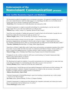
following vessels would avoid entering’. They state that the boundary ‘is more of a psychological barrier than a stone wall’ and use a comparison with particles with electrical charges of the same sign, i.e.: ‘the repulsive force increases as the separation decreases’. To quantify the domain boundary, Goodwin (1975) hypothesized that if a ship domain exists, up to a certain distance from each ship, the density of ships will be lower than the average density of ships in the particular area. She defined the range of the domain boundary (also referred to as ‘domange’) as the distance from the ship to the point where the actual density is equal to the average density. Using simulator experiments she illustrated that the domange varied as a function of bearing. Hansen et al. (2013) used a large amount of recorded AIS data to estimate the comfort ellipse which describes the minimum comfortable distance (referred to by the authors as the minimum ship domain) between two ships. Various shapes for the ship domain have been proposed, but they all have in common that they are represented by an asymmetrical spatial buffer around the ship (that should be kept clear of other vessels). When the size of the ship domain is determined by encounter-rate, one could argue that the size of the domain behind the ship is determined by a spatial requirement which is intended to protect against low-closure rate encounters, whereas the spatial part in front and to the sides is determined by a reaction/manoeuvre time assumption. Indeed several of the proposed asymmetrical shapes provides a larger buffer for traffic approaching ownship from ahead than traffic closing in from aside or astern. In (Goodwin, 1975) it is suggested that ‘an ellipse with major axis inclined to the direction of the ship’s head and this certainly provides the best approximation to the domain shape’. Figure 1 shows three proposed shapes for the ship domain.
Figure 1. Different shapes of the spatial boundaries proposed for the ship domain (A: Goodwin, 1975; B: Coldwell, 1983; C: Davis et al., 1980)
2.2
Collision avoidance in the nautical domain
The basis for the operator support concept described in this paper is the presentation developed for the Integration Collision Avoidance and Navigation System (INCAS - Chase and Tiblin, 1971) and the High Speed Ship Collision Avoidance and Navigation System (HICANS - Pucket, 1983). The INCAS system which was developed in the Seventies of the previous century added an important piece of information to the Plan Position Indicator (PPI). Rather than only providing numerical information about the closest point of approach that would result from maintaining current course and speed, it computed the required 3
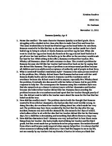
change in the course of ownship that would cause the relative velocity vector of the other vessel to intersect ownship position and depicted the area where the collision would take place, the Predicted Area of Danger (PAD). In (Pucket, 1983) this is described as follows: ‘The PAD is an ellipse drawn around the PPC representing an area in which the Closest Point of Approach (CPA) will be less than the value selected by the operator’. The Point of Possible Collision (PPC) is ‘a point along the target ship’s trackline where a collision would occur if the target maintained its course and speed, and if ownship steered towards that point at its present speed. More simply, the PPC is the visual display of a torpedo firing solution for a torpedo travelling at own ship’s speed’. The depiction of the PAD relative to ownship supports the operator in answering the ‘what-if’ manoeuvre question by shifting part of the mental effort required to answer the ‘what-if’ manoeuvre question from the officer of the watch to the system. Figure 2 illustrates the problem to be solved:
Figure 2. With the current course and speed, minimum distance to traffic 2 occurs in CPA. When turning δ degrees right, ownship will collide with traffic 2 in PPC
The situation is figure 2 is a track-up ownship-referenced planview in a relative coordinate system. Ownship is located in the origin (point 1), with velocity indicated by vector v 1. Another vessel is located at a distance d1 in point 2, with a velocity indicated by vector v2. The relative velocity vector (v2 – v1) lies along line l1. Since l1 does not intersect ownship position, the future positions will never coincide. The smallest future distance (d2) between ownship and the traffic is at the CPA point. A collision would occur if the relative velocity vector lies along line l2 (intersecting ownship position). To realize the relative velocity vector, ownship would need to turn δ degrees to the right. The collision would occur in the point labeled PPC.
4
2.3
Collision avoidance in the aeronautical domain
In the aeronautical domain, the Traffic Alert and Collision Avoidance System II (TCAS-II) provides pilots of manned aircraft with collision avoidance guidance. The collision detection function is performed by estimating the distance between ownship and other traffic at the closest point of approach (CPA), testing whether this distance is smaller than a specified collision distance threshold, and if so timely commanding a manoeuvre to prevent this from occurring. TCAS-II uses a constant range-rate test as part of a criterion to determine whether a collision risk exists. The amount of range-acceleration that is allowed in the test determines the horizontal miss distance. Note that passing the test does not imply that immediate action must be taken, also the time to CPA must be below a predefined (tau) threshold. With TCAS, the time to CPA is obtained from range (measured by using the time between an ownship transmitted interrogation and an intruder generated reply) divided by (computed) range-rate. To provide timely alerts in low closure-rate encounters where computed time to CPA can be above the alerting threshold for very small distances, a spatial alert threshold is defined (FAA, 2000), referred to as Dmod. In the actual algorithm, the tau and Dmod are combined into a single test referred to as modified tau (Munoz et al., 2013).
3
PROVIDING OPERATORS WITH AWARENESS OF CONFLICTING TRAFFIC SITUATIONS
A collision hazard situation is preceded by a geometry in which ownship is no longer ‘well clear’ of other traffic. To minimize the occurrence of situations in which collision avoidance manoeuvres must be performed, operators should have timely awareness of potentially conflicting traffic situations. Conflict detection is typically performed by testing whether the current course and speed will result in a future situation in which ownship is no longer ‘well clear’. Resolution is achieved by determining and executing a manoeuvre that will keep ownship well clear. To support the operator with automated conflict detection and resolution functions, ‘well clear’ has to be objectively defined and quantified. Options to be considered are the contours of the ship domain or a spatial/temporal separation criterion. 3.1
The need to anticipate
To make informed decisions, a human operator must be timely aware of the underlying issues and potential solutions. For the navigation task this implies that the human operator should not be surprised by the system asking for a manoeuvre decision and be aware of all constraints that impact the outcome of the choice. Based on the 3-level classification used for Situation Awareness (Endsley, 1989), the following more specific scheme has been proposed for conflict awareness (Suarez et al., 2012) (Table 1).
5
Table 1. The 3 levels of Conflict Awareness Conflict Awareness Level
Definition
Minimum Traffic Information & Quality
Information Processing
1. Perception
Awareness of conflict potential given proximity of traffic
Traffic relative position with low quality
None
2. Comprehension
Awareness of location and time of conflict
Traffic relative position and velocity with medium quality
Conflict Detection
3. Anticipation
Awareness of conflict sufficient to optimize avoidance manoeuvre or determine unsafe manoeuvres
Traffic relative position and velocity with high quality
Conflict Probing
With level 3 conflict awareness, an operator is able to anticipate manoeuvre requests from a support system or even take action before such a decision is requested. In order to ensure that the operator is timely aware of constraints that impact the manoeuvre decision, he/she must be aware of the proximity of all potential hazards. For static hazards this is typically achieved using an electronic chart display in which all obstacles are presented relative to ownship. However, although the location of other traffic can be depicted in real-time, unlike static hazards the areas to be avoided in order to remain well clear of other traffic are not directly visible. The real-time depiction of the computed hazard areas makes the invisible visible, yielding directly actionable information. Based on the INCAS and HICANS concept of presenting the PPC and PAD, the idea to provide operators of unmanned aircraft with a depiction of the three-dimensional conflict space was pursued (Tadema and Theunissen, 2008). Results from a simulation based evaluation showed that for the detection of conflicts, the missed detections reduced from 9% without conflict probe support to zero in case of depiction of the conflict space. Additionally, the amount of unwarranted manoeuvres was reduced by a factor of 26. This indicates that the use of conflict probes considerably increases the operator’s ability to distinguish conflicting traffic situations from conflict free ones. Given these promising findings it was decided to also implement a conflict probing function in the navigation support system that was being designed in the context of the Combined System for Harbor, Infrastructure and Littoral Domains (CSHIELD) project (Theunissen, 2012). Two important differences exist between the presentation of conflict areas and the PADs used in HICANS. 1. For a PAD it is assumed that when the future positions lie within the PAD the probability of a collision is assumed to be very high. The presentation of a conflict area is based on the concept that the conflict area is defined by a threshold that, when violated, results in a situation in which safety is impaired because there is a higher probability of a collision (e.g. 5% or 10%). The boundaries of a conflict area are more comparable to the contours of the ship domain. 2. Whereas a PAD only requires the computation of the PPC point (around which an ellipse is drawn), the computation of the conflict area requires the online computation of the locations where a t.b.d. threshold is crossed. As will be illustrated in the third part of this paper, such a threshold can comprise both a spatial and a temporal component. This approach also differs from a modified PAD as proposed in (Zhao-lin, 1988). 6
3.2
Defining and quantifying the domain boundary
To ensure sufficient manoeuvre margin in case the predicted distance at CPA decreases below the collision distance, a minimum spatial separation requirement can be defined. Such a separation requirement will need to consider assumptions regarding surveillance accuracy, response time and manoeuvring performance. ATC uses a horizontal separation of 5 NM and a vertical separation of 2000 ft (1000 ft in case of Reduced Vertical Separation Minima). Besides procedural separation, it is required that a pilot passes ‘well clear’ of other aircraft when an encounter occurs. In (Weibel et al., 2011) it is pointed out that to allow for pilot judgement the regulatory language concerning well clear is intentionally subjective, but that a technical implementation of an equivalent function requires an objective definition. In the context of the ship domain, already in 1975 Goodwin proposed to ‘take into account the accuracy of navigation’ and ‘set standards based on the domain boundaries such that the probability of collision was below a certain level’ (Goodwin, 1975). Similarly, Weibel et al. (2011) propose a risk-based approach to define an objective well clear boundary which they define as ‘a relative state between aircraft for which the risk of collision is acceptable’. Based on an analysis of millions of generated encounter, Weibel et al. (2011) conclude that ‘The horizontal contours of 5% collision risk suggest that a well clear boundary based on this threshold would extend approximately 8000 ft ahead of an aircraft, 3000 ft. laterally, and 3000 ft behind. A simplification of the complex shape would need to be derived that reflects the acorn-like shape ahead of the aircraft’. Figure 3 presents two different shapes that meet the size criteria. The shape in Fig. 3b more closely resembles the 5% contour of conditional Near Mid Air Collision (NMAC) risk in the horizontal plane presented in (Weibel et al, 2011).
Figure 3. Two different shapes of spatial buffers for P(NMAC)=0.05 based on the dimensions proposed in (Weibel et al., 2011)
7
Similar to the well-clear boundary proposed in (Weibel et al, 2011), the ship domain is specified using a spatial-only threshold. Already in 1975, Goodwin indicated that for the domain size ‘it is likely that there may well be an interaction with the speed of ships’ (Goodwin, 1975). Also, in (Zhao-Lin, 1993) it is concluded: ‘Fifthly, the size of a ship domain is affected by the relative speed of the two ships. The higher the relative speed, the larger will be the ship domain’. Colley et al. (1983) recognized this limitation and proposed a solution which was inspired by then recent developments for collision avoidance systems in the aerospace domain: the use of range over range-rate as a measure for temporal distance. 3.3
Limitations of spatial-only separation
Whereas from a surveillance perspective the buffer needed to account for surveillance inaccuracy is independent of the direction of travel, this is not the case for the buffer needed to manoeuvre. It is apparent that a ship or aircraft approaching ownship from the front will reach the Collision Hazard Zone (CHZ; the area around ownship where the probability of a collision is assumed to equal 1) much earlier after a violation of a constant distance separation threshold than an intruder approaching from behind. To establish the minimum size of a constant range spatial separation buffer that, when violated, will provide a timely warning, a worst-case assumption about the maximum relative velocity has to be made. For all other velocities, the buffer is basically too large (from a reaction time perspective). Whereas at present for ATC the surveillance inaccuracy may be the dominant factor, thus warranting a (horizontally) circular separation buffer, this may not be the best option for concepts of self-separation that benefit from much increased surveillance accuracy (as provided by ADS-B for aircraft and AIS for ships). Furthermore, although the shapes shown in Fig. 3 accounts for the effect that intruders approaching the CHZ from behind do not require as much spatial margin as intruders approaching from the front, it does not distinguish between the range of speeds with which an intruder could approach. This latter aspect can be taken into account when also using a temporal threshold.
4
USING SPATIAL AND TEMPORAL THRESHOLDS
As mentioned earlier, TCAS-II uses both a spatial and a temporal threshold. Figure 4 illustrates the issue that occurs when using a spatial-only alerting threshold for separation and a spatial-temporal alerting threshold for collision avoidance. For a high enough closure-rate, the range can still be larger than the spatial separation threshold, but the time to CPA is already smaller than the tau ALERT. The combinations of range and closure-rate for which this can occur are indicated by the upper-right triangle in Figure 4. The top-view in Figure 5 further illustrates this issue by showing where a spatial-only threshold will yield a separation warning (independent of traffic direction and velocity) and where a temporal alert threshold will yield an alert for three different speed ratios, VTRF = [0.5 ; 1.0 ; 1.5] VOWN, (only in case of traffic on a collision course).
8
Figure 4. Issue due to the use of a spatial separation threshold and a spatial/temporal collision avoidance threshold
Figure 5. Spatial threshold (solid) and temporal thresholds converted into spatial thresholds (dashed) based on relative velocity
9
At t0, ownship is in location 1. The solid red area around ownship represents the area within which the probability of a collision is assumed 1. Ownship travels with a velocity V OWN and is exactly tauALERT seconds away from location 2. In this example it is assumed that the velocities of other traffic lie within the range of 0.5 VOWN and 1.5 VOWN. The dashed circles represent the locations where the temporal alert threshold will be crossed for traffic on a collision course (traffic that will arrive in point 2 in tau ALERT seconds) with velocities of 0.5, 1 and 1.5 of ownship velocity. The large green circle around ownship represents the required spatial separation DCAUTION. The green area that is not covered by the yellow circles (Figure 5 and Figure 6a) represents the space within which a separation violation is declared, but the temporal distance is always larger than tau ALERT. The part of the yellow circle that is not covered by the green circle (see also Figure 6c) represents the locations where the temporal separation between ownship and an intruder on a collision course will already have decreased below tauALERT before the separation threshold specified by DCAUTION is violated. To prevent such situations from occurring, the spatial separation threshold has to be selected larger than the product of the alerting time constant (tauALERT) and the maximum possible closure rate (in this example 2.5 times VOWN). If a constant size spatial threshold is used to provide timely separation alerts in case of high closure rate encounter, the size of the green area will also increase. From Fig. 5 it can be seen that by changing the green circle into a shape similar to Fig. 3b, the forward spatial alerting threshold can be extended beyond the temporal threshold without affecting the size of the area shown in Figure 6a. However, this amount of extension is determined by the maximum closure-rate, and as indicated by Weibel et al. (2011) for the existing TCAS-II systems this implies: ‘If it becomes necessary to not issue TCAS Resolution Advisories within the well clear boundary, it will need to be extended far beyond a low collision risk threshold’. With Goodwin’s density-based definition of the domange, there will be traffic inside the ship domain. In the comments on (Jingsong et al.,1993) Goodwin points out that: ‘Some encounters cannot be avoided and are deliberate manoeuvres. They are only likely to turn to collision risk when human error is involved’.
Figure 6. (a) Area where spatial separation is violated but temporal separation is still met, (c) Area where temporal threshold is violated, and spatial threshold will not yet have provided a warning
10
The use of a combined temporal-spatial threshold in TCAS-II inspired the change from a spatially defined conflict boundary to a temporal-spatial one. The use of a temporal threshold allows the spatial separation criterion (DCAUTION) to be reduced and the too early/ unnecessary warnings caused by traffic traveling through the green zone depicted in Figure 5 can be eliminated. However, similar to the low closure rate issue with TCAS-II, a spatial separation criterion is still required. For a certain range of intruder velocities, low closure rate conflict geometries can result in a situation in which the spatial separation decreases to a value close the collision distance threshold before the temporal separation threshold is crossed (Figure 6b). To provide a timely separation warning, DCAUTION must be selected based on a margin relative to DALERT. In recent research into the integration of unmanned aircraft into controlled airspace, the concept of a hybrid spatial-temporal buffer has been proposed as the definition of a volume around ownship that should be maintained ‘well clear’ (Theunissen et al., 2013). Figure 7 presents the concept in terms of spatial and temporal thresholds.
Figure 7. Use of both a spatial/temporal separation threshold and a spatial/temporal collision avoidance threshold
To evaluate the concept, the algorithm used for the computation of a spatial threshold was replaced with an algorithm using both a spatial and a temporal threshold (as illustrated in Figure 7). To illustrate the additional margin obtained for higher closure-rates, Figure 8 shows the situation with a spatial only threshold of 0.2 NM, and Figure 9 the same situation with a spatial threshold of 0.2 NM and a temporal threshold of 60 seconds.
11
Figure 8. Example conflict area (solid yellow) when using spatial separation threshold of 0.2 NM From Figure 8 it can be observed that to prevent getting closer than 0.2 NM to target 05, ownship will have to manoeuver around the solid yellow area intersecting the current track of ownship. The read areas inside the yellow areas in Figure 8 indicate the Collision Hazard Zone. In the example in Figure 9 the depiction of these red areas has been disabled.
Figure 9. Same situation as in Fig. 8, but now with the addition of a temporal separation threshold of 60 seconds. Note how the areas extends towards ownship
12
From Figure 9 it can be observed that to prevent getting within 60 seconds and/or 0.2 NM of target 05, ownship will have to maneuver earlier as compared to the situation depicted in Figure 8. The addition of the temporal threshold results in an extension of the depicted conflict space towards ownship. This is equivalent to an increase of the ship domain in the forward direction of ownship. In case ownship would increase speed, the area would grow further towards ownship. Note that the 0.2 NM and 60 seconds have been selected for illustrative purposes only. Current research is addressing the development of a rationale for the systematic selection of values for the temporal and spatial alerting thresholds.
5
CONCLUSION
In the past 40 years, research into systems for collision avoidance and concepts to define the area that is needed for safe navigation have resulted in important innovations in the nautical and aeronautical domain that have significantly contributed to an increase in safety. In the current paper, the concept and underlying rationale for a system to provide the operator of an unmanned ship with level 3 conflict awareness has been described in the context of ideas and findings from several research projects, some of which date back to over 40 years ago. To support the operator with automated conflict detection and resolution functions, the PPC / PAD visualization concept has been used to visualize the area that should be kept clear of other traffic. An important difference between the concept described in the current paper and earlier work is that rather than only visualizing the area where a collision is predicted to occur, the area that has to be prevented in order to remain ‘well clear’ is computed and displayed. To achieve this, ‘well clear’ has to be objectively defined and quantified. Options to be considered are the contours of the ship domain or a spatial/temporal separation criterion. Based on an analysis of limitations of a spatial-only ‘well clear’ boundary, it has been illustrated why a temporal element must be included, which in turn means that besides current separation, relative velocities need to be taken into account in the algorithm. The basis for the modification to the original, spatial-based conflict probe algorithm and display is the collision detection algorithm used by the Airborne Collision Avoidance System (ACAS) and Traffic Alert and Collision Avoidance System (TCAS). The spatial/temporal concept has been integrated into an earlier developed navigation support system for unmanned vessels. Current research is addressing the development of a rationale for the systematic selection of values for the temporal and spatial alerting thresholds.
REFERENCES Allen, C.H. (2012). The Seabots are Here: Should they be Treated as ‘Vessels’? The Journal of Navigation, Vol. 65, pp. 749-752, Royal Institute of Navigation. Chase, K.H. and B.V. Tiblin (1971). INCAS Integrated Navigation and Collision Avoidance System, Journal of the Institute of Navigation, volume 18, No. 2. Coldwell, T.G. (1983). Marine Traffic Behaviour in Restricted Waters. The Journal of Navigation, Vol. 36, No. 3, pp. 430-444, Royal Institute of Navigation. Colley, B.A., R.G. Curtis and C.T. Stockel (1983). Manoeuvring Times, Domains and Arenas. The Journal of Navigation, Vol. 36, pp. 324-328, Royal Institute of Navigation. 13
Davis, P.V., M.J. Dove and C.T. Stockel (1980). A Computer Simulation of Marine Traffic Using Domains and Arenas. The Journal of Navigation, Vol. 33, pp. 215-222, Royal Institute of Navigation. Endsley, M.R. (1989). “A Methodology for the Objective Measurement of Pilot Situation Awareness,” in Proceedings of the 1989 AGARD symposium on Situational Awareness in Aerospace Operations, pp. 19. FAA (2000). Introduction to TCAS II Version 7. Fujii, Y. and K. Tanaka (1971). Traffic Capacity. Journal of the (Royal) Institute of Navigation, Vol. 24, pp. 543-552. Goodwin, E.M. (1975). A Statistical Study of Ship Domains. Journal of the (Royal) Institute of Navigation, Vol. 28 No.3, pp. 328-344. Jingsong, Z, W. Zhaolin and W. Fengchen (1993). Comments on Ship Domains. Journal of the (Royal) Institute of Navigation, Vol. 46, No.3, pp. 422-436. Munoz, C., A. Narkawicz and J. Chamberlain (2013). A TCAS-II Resolution Advisory Detection Algorithm. Proceedings of the AIAA Guidance, Navigation and Control Conference, August 19-22. Puckett, L. (1983). HICANS – Navigation for High Speed Ships. Journal of the Institute of Navigation, Vol. 30, No. 2, pp. 107-122. Suarez, B., K. Kirk and E. Theunissen (2012). Development, Integration and Testing of a Stand-Alone CDTI with Conflict Probing Support. Proceedings of the AIAA Infotech@Aerospace conference, June 1921, Garden Grove, CA. Tadema, J., & Theunissen, E. (2008). Design and Evaluation of a GUI for Operator Involvement in Airborne Conflict Detection and Resolution. Proceedings of the 27th Digital Avionics Systems Conference, pages 5A2.1-5A2.12, St. Paul, Minnesota. IEEE catalog number 978-1-4244-2208-1/08. Theunissen, E. (2012). Design and Evaluation of Operator Support Functions for the CSHIELD Platform. st Proceedings of the 31 Digital Avionics Systems Conference. Theunissen, E., B. Suarez and M. Uijt de Haag (2013). From Spatial Conflict Probes to Spatial/Temporal nd Conflict Probes: Why and How. Proceedings of the 32 Digital Avionics Systems Conference. Weibel, R.E., M.W.M. Edwards and C.S. Fernandes (2011). Establishing a Risk-Based Separation Standard for Unmanned Aircraft Self Separation. Proceedings of the Ninth USA/Europe Air Traffic Management Research & Development Seminar, 14-17 June, Berlin, Germany. Zhao-lin, W. (1988). Analysis of Radar PAD Information and Suggestion to Reshape the PAD. Journal of the (Royal) Institute of Navigation, Vol. 41, No.1, pp. 124-129.
14