developing RF identification (RFID) wireless technology. Two antennas, based on Koch and Hilbert fractal geometries, are designed and optimized for 0.953 ...
Conformal Fractal Loop Antennas for RFID Tag Applications Andrey S. Andrenko
Fujitsu Laboratories LTD. YRP R&D Center, 5-5, Hikarino-Oka, Yokosuka 239-0847, Japan E-mail: andrey@,labsfujitsu.com
Abstract This paper presents the design of novel conformal fractal loop antennas proposed for the rapidly developing RF identification (RFID) wireless technology. Two antennas, based on Koch and Hilbert fractal geometries, are designed and optimized for 0.953 GHz RFID band. Key design requirement has been maximizing the antenna gain and directivity that results in increasing the read range of RFID system. Full-wave EM simulation results illustrating the radiation characteristics ofthe proposed antennas are presented. Antenna layout has been defined to fit the specified size of RFID tags. The design trade-off between the space-filling properties ofthefractal geometry and required antenna gain performance is discussed. 1. INTRODUCTION
Radio frequency identification (RFID) technology relates to short-range wireless communications and uses the radio frequency to read certain information on a device known as a tag. Originally, basic ideas of RFID operation have been formulated a decade ago while the last several years have seen a renewed interest leading to various practical implementations and designs. In general, any RFID system consists of one or more tags and read/write (R/W) device incorporating, as its main part, a R/W antenna. Tags are devices that can come in many sizes and form, but are usually small and lightweight. They are commonly used for wireless data communication with R/W devices at distances ranging from a few millimeters to several meters. Because of its flexibility and convenience RFID technology is now used in a variety of applications including supply chain processing, security systems, inventory control, mail delivery, and counterfeit product prevention [1]. Most RFID tags contain integrated circuit (IC) chip, to store and process data, and also an integrated antenna, which is used as the communication interface with R/W antenna system. The IC chip requires power to operate, which in the initial designs was supplied by a battery. Recently, most applications require the tags to be small and inexpensive, so the so-called passive (no-battery) chips became common and widely used. Read-only tags are used when the data is to be programmed once, and tag in such a case only sends the stored information to the reader antenna. Readwrite tags can be reprogrammed when the information needs to be updated according to the needs of the application. Several frequency bands are used in RFID deployment, such as low frequency (LF) at 125 - 135 KHz, high frequency (HF) at 13.56 MHz known as International Scientific and Medical (ISM) band, ultra high frequency (UHF) band from
860 MHz to 960 MHz, and 2.45 GHz band. Much effort is currently being devoted to the development of various UHF applications and solutions. Standards organizations are working with governments to harmonize UHF frequencies. However, today the bandwidth of this frequency varies from region to region. The United States has specified 915 MHz while the EU has allocated 868 MHz for RFID applications. Recently, Japan has specified 950 to 956 MHz as UHF RFID band. Therefore, this variation of frequency allocation requires that RF manufacturers produce country-specific tags and R/W devices creating a potential disconnect in the attempts to come up with the truly seamless international supply chain. This paper presents the design and discusses the performance of the conformal fractal loop antennas optimized for RFID tag applications for Japanese market. There are several key performance requirements of all UHF RFID systems. The first critical performance characteristic of all RFID systems is read range. It depends on the antenna gain of both tags and R/W system. That is why high antenna gain is an important requirement of any RFID tag antenna design. Many applications demand small and conformal tag antennas, which are to be attached to compact packages of various forms. Taking into account the performance requirements noted above, minimizing the size of RFID tag antennas while maintaining reliable radiation characteristics presents unique design challenges. Finally, considering the commercial mass production of RFID systems, the tag antenna design and manufacturing have to be as cost effective as possible. Currently, the price demands for tags are in the range of 5 to 10 cents and this dictates certain requirements in choosing the manufacturing technology and materials used. In this paper, the design of two conformal loop antennas optimized for RFID tag applications is
presented. The antenna circuits are printed on a thin dielectric layer as such a technology is preferable for implementing conformal RFID tags in ID cards, mail delivery, and supply chain processing. The tag design should also permit the possibility of direct integration of antenna element and IC chip. In most cases, UHF RFID chips are characterized by high impedance so that a tag antenna has to possess similar input impedance. We begin our analysis with the discussion on the radiation characteristics of several known fractal geometries used in the loop antenna design. Next, the results of EM simulation illustrate the performance of the proposed fractal loop antennas in terms of design trade-off between the space-filling properties of the fractal geometries resulting in lowering the resonant frequencies and achieving high antenna gain and directivity. In this study, CST Microwave Studio has been used as a full-wave EM simulation tool. Finally, we discuss the possibilities of practical applications of the proposed loop antennas for the design of novel wireless communication devices. 2. FRACTAL LOOP ANTENNAS AS RFID TAG ELEMENTS
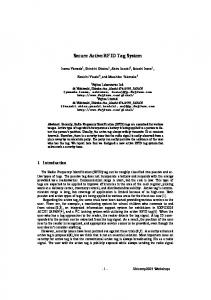
Fractal geometries have attracted considerable interest for the novel antenna designs in recent years [2-5]. The term fractal is used to define a class of complex shapes characterized by the so-called selfsimilarity of their structures, where small parts of the geometry duplicate the whole geometry but on a reduced scale. The iteration process is implemented to mathematically generate the fractal geometry. Fractal antennas thoroughly studied in the recent literature include Koch curve monopoles [3], Sierpinski gasket monopoles [2], Minkowski fractal loops [3], and Hilbert fractal monopole and dipole antennas [4,5]. Figs. 1 and 2 show some examples of fractal-antenna geometries. Mostly, the studies of fractal antennas performance have been centered on their space-filling properties leading to antenna miniaturization and multi-frequency behavior. Fractal antenna performance has also been compared with that of other non-conventional-geometry radiators [3].
{f
-J-1-
Fig. 1. Examples of Minkowski Island (left) and Koch fractal (right) loops based on square and circle geometry, respectively.
,.
n-i
n -O jii
a2 'D
= fed2
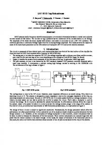
n- 3
Fig. 2. Generation of strip pattern of classical Hilbert fractal monopole antenna [4]. Let's now briefly consider the radiation properties of fractal loop antennas in comparison to those of conventional loops. In contrast to dipole and monopole, a loop antenna responds mostly to the magnetic field B of the incident EM wave. The 2terminal port voltage is thus proportional to time change of the magnetic flux (D through the loop, which is in turn proportional to the area S enclosed by the antenna. In simple form it can be expressed as
V oc
at
c, c BS
(1)
Therefore, if a loop antenna occupies the area a x b, the maximum voltage will be obtained when the antenna shape is a rectangular loop with sides a and b. In addition to this, maximum antenna gain and directivity are also produced by a rectangular loop. On the other hand, fractal geometry reduces the area enclosed by a loop antenna, which is designed to fit the same area a x b , and as a result it lowers antenna gain. For example, fractal loop antennas shown in Fig. 1 have smaller gain and directivity as compared to the conventional loops of the shapes on which they are based. Referring to the Hilbert fractal loop antenna, it should be noted that each next iteration in generating the fractal geometry reduces the area enclosed by the fractal loop. In some cases, fractal shape of a narrow strip loop antenna may increase its Ohmic resistance as compared to radiation resistance, which decreases the antenna efficiency [6]. Thus, in designing fractal loop antennas for the specific wireless applications, one has to consider an important design trade-off between antenna-size reduction and achieving good radiation
performance.
2.1. Modified Koch Fractal Loop Antenna
Taking into account the performance requirements noted above, fractal loop antenna has been designed for RFID tag application with 0.953 GHz operation frequency. Fig. 3 shows the layout of a proposed Koch fractal loop antenna, which is printed on a 38 ptm - thick lossy dielectric layer of e =3.2 and tan6=O.O1 with the size 75 mm X 75 mm. This antenna has been designed as a tag antenna occupying the area 65 mm X 65 mm. The antenna is composed of the straight strip elements 0.3 mm wide and 1 mm long. In Fig. 3, a fractal element, which is a 3rd iteration Koch fractal, is also indicated and connecting these elements forms the total antenna circuit. At the design frequency, resonant length of this antenna is L = 1.832. Two-port balanced feed is used in the simulation. The antenna layout has been optimized to increase the area enclosed by the loop so that according to (1) one can expect to obtain a significant level of antenna gain.
2-dimensional radiation pattern in the vertical xz plane is shown in Fig. 5. The pattern is almost omnidirectional and this result is very attractive for RFID tag applications.
Fig. 5. Antenna gain in the vertical x-z plane at 0.953 GHz.
Next, let's consider the current distribution
on
antenna circuit. Figs. 6-8 show vector surface current taken at 3 phase-instants with the step 45 degrees at GHz.~~~~~~~~~~~~~~~~~~A the resonant frequency. Zero-value current points are let'scurrent considertsegments he distribution on~~~~~~~~~~~~~~~~~~~~~~~~~~~~~~~~~~~14........ located at the middle of Next,side while the
maximum current is induced on the segments attached to the port and those on the opposite part.
Fig. 3. Layout of the proposed Koch fractal loop antenna printed on thin dielectric layer.
Fig. 4 depicts 3D pattern of antenna gain of the total E-field. Maximum gain is 2.53 dB, which is a good result considering a relatively small area 65 mm X 65 mm occupied by a loop operating at 0.953 GHz. 4.dS
Fig. 6. Vector surface current on the fractal antenna circuit at 30 degrees phase instant at 0.953 GHz. Si .i 3Xi M-
MIS
Fig. 4. 3D pattern of antenna gain of the total E-field at 0.953 GHz.
Fig. 7. The same as Fig. 6 but at 75 degrees phase instant.
Fig. 8. The same as Fig. 6 but at 120 degrees phase instant.
Fig. 9. Layout of a butterfly-like fractal loop antenna printed on thin dielectric layer.
Because of two-line symmetry of the proposed fractal loop the current distribution possesses the same symmetry. The radiation pattern depicted in Fig. 4 is a result of such current symmetry. 2.2. Butterfly-Like Fractal Antenna In this section, the results of EM simulation and optimization of a novel fractal loop antenna designed for RFID tag applications are presented. In the first stage, the antenna layout is generated by using a 2nd iteration (see Fig. 2, n=2) Hilbert fractal curve. Next, loop antenna layout is modified in order to fit the required antenna size. Finally, the straight strip segments of a 2nd iteration Hilbert curve are replaced by 2-strip corner elements, which leads to increasing the total length of the loop antenna and, as a result, lowers the antenna resonant frequency while maintaining the dimensions of antenna structure. The antenna has been designed to fit the ID card-size rectangular area with dimensions 45 mm X 75 mm. In the simulations, lossy metal with conductivity C = 2.7 x 10⁷ S / m has been used and the metal strips forming the loop structure are characterized by the width w = 0.3mm and the thickness tm = 9,m. The material parameters of the dielectric substrate layer are as follows: r=3.2, tan6=0.01 while its thickness is t = 3 81u . Total loop length has been optimized for RFID band operation to provide 0.953 GHz antenna resonant frequency. As a result, the layout of the proposed fractal antenna has been defined as shown in Fig. 9. The top view of fractal loop antenna layout is presented in Fig. 10. Because of the fractal geometry realized here this loop antenna can be called the butterfly-like fractal loop. In constructing the fractal curve an additional design requirement, besides space-filling properties, has been the minimization of parasitic mutual coupling between the fractal loop segments on which an induced currents substantially differ. At the design frequency, resonant length of butterfly-like fractal loop is L =1.552 that is shorter than the length of Koch fractal loop antenna presented in Section 2.1.
Feed Port
Fig. 10. Top view of the proposed fractal loop antenna based on Hilbert curve. Simulated return loss of the designed fractal loop antenna is shown in Fig. 11. It indicates that the bandwidth of this antenna obtained at -10 dB level makes possible two-band operation at 0.915 GHz and 0.953 GHz RFID frequencies. SaIrhvletr Magnitudie In d
0.6
07
0.
0.9
11
1.-
F"teiY I GHz
Fig. 1 1. Calculated return loss of butterfly-like fractal loop antenna. Smith chart of the antenna S- II parameter calculated for 100 Ohm reference port impedance is shown in Fig. 12. It is seen that the input impedance
of the proposed fractal loop antenna at the resonant frequency is close to 100 Ohm. o
S t
19.t B.e,
SI Xaofa@ti
.t53)gWj
O Si52 93634IM (t8&40 v -vi MA Mar
th
gI,,l
}
Fig. 15. Antenna gain in the vertical y-z plane at 0.953 GHz.
Fig. 12. Smith chart of S-Il parameter. Next, consider the radiation characteristics of the proposed butterfly-like fractal loop antenna. 3D radiation pattern of antenna gain is shown in Fig. 11. Simulated maximum gain is 1.75 dB and directivity is 1.91 dBi. The gain is somewhat smaller than for the previous antenna design, which is a result of a decreased area enclosed by the butterfly-like fractal loop.
Figs. 14, 15 present the radiation patterns in two vertical planes. It is seen that in x-z plane this antenna operates like omnidirectional radiator, which is again a welcome result for RFID tag operation. Figs. 16-18 depict the calculated vector surface current on the antenna circuit at 0.953 GHz. The antenna layout is symmetrical with respect to x-axis only so that one-line symmetry is observed. In terms of current distribution, the design of loop layout should be done to maintain large enough spacing between the segments of maximum and zero-value current. Ahm-
field at 0l953 G z-
_~~~~~~~~~~~ e
~ ~ ~ ~ ~ ~ ~ ~ ~ ~olf ~ ~ ~ ~ ~ ~th~ ~ ~ . . . .total BFig.~~~~ 13 3D patr of anen._~ ~ ~ ~ ~ gai _/~~~~~~~~~~~~~~~~~~~~~~~~~~~~~~~~~~~~~~........ .
antennaofpat3DF13.igain ergn. ofthe E-~ ~total ~ ~ ~ ~ ~ ~ ~ ~ ~ ~. . GHz.a~ 0~t.953~ ~ ~ ~ ~ ~ ~ ~ ~ ~ ~ ~ ~ ~ ~ ~ ~ ~ ~ ~ ~ ~ ~ ~ ~ ~ ~ ~ ~ ~ ~ ~ ~ ~ ~ . . . . field T ypi FJ ti It ir r.A
. m"L7 _{g
Far equeng phose
Sorface uurfomt (pook] k-fieli ff*O.SS31 III
go U4 ny w -At 13- 1 JIU
04353
Fig. 16. Vector surface current on the proposed antenna circuit at 30 degrees phase instant. ,.A .1
1l
M"a
Fig. 14. Antenna gain in the vertical x-z plane at 0.953 GHz.
t *,
M... Far equencv phose
.g,f"c.
9P..4k]
-fi.ld 4 f*o. gsA I
W. "04 A/. tiAM
I I
t 13.17q,
tju 9A.9
/X 0. 4!5
Fig. 17. The same as Fig. 16 but at 75 degrees phase instant.
5 36
[4]
25
u tl.a 7. 4.1
a,
[5]
[6] yp.
o
M".i to,. M..
o
- 3d ... o
F'reqmency phose
o -
-Ig , f .... ep..4k] f-f . Id 4 f*o. 9SIA I I I G4.98M A . t 13.17,91, ../I
041353 IZO dcgr-e-es
9A.9yu 0Xk 45
Fig. 18. The same as Fig. 16 but at 120 degrees phase instant. 2.3. Experimental Results
The performance of the proposed fractal antennas has also been verified by measurements. The measured radiation patterns are in very good agreement with the simulation results presented above. Maximum measured antenna gain of 2.51 dB for the modified Koch fractal antenna and 1.74 dB for the butterfly-like fractal antenna have been obtained. 3. CONCLUSIONS We have presented the design of conformal fractal loop antennas specifically optimized for the RFID tag applications. First design is based on the modified Koch fractal geometry while the second one is related to the modified 2nd iteration Hilbert curve. The antenna geometries have been defined towards maximizing the antenna gain and directivity. EM simulation results obtained describe the radiation characteristics as well as induced current density distributions on the antenna circuits. Simulation results are in good agreement with the measurement data. In should be noted that the proposed loop geometries are also attractive candidates for the design of various wireless communication components.
4. REFERENCES [1]
[2]
[3]
"Item-Level Visibility in the Pharmaceutical Supply Chain: A Comparison of HF and UHF RFID White Technologies", paper by Philips Semiconductors, TAGSYS, and Texas Instruments Inc., July 2004. D. H. Werner, and S. Ganguly, "An Overview of Fractal Antenna Engineering Research", IEEE Antennas and Propagation Magazine, Vol. 45, No. 1, pp. 38-57, February 2003. S. R. Best, "A Discussion on the Significance of Geometry in Determining the Resonant Behavior of Fractal and Other Non-Euclidean Wire Antennas",
IEEE Antennas and Propagation Magazine, Vol. 45, No. 3, pp. 9-28, June 2003. J. Anguera, C. Puente, E. Martinez, and E. Rozan, "The Fractal Hilbert Monopole: A Two-Dimensional Wire", Microwave and Optical Tech. Lett., Vol. 36, No. 2, pp. 102-104, January 2003. K. J. Vinoy, K. A. Jose, V. K. Varadan, and V. V. Varadan, "Hilbert Curve Fractal Antenna: A Small Resonant Antenna For VHF/UHF Applications", Microwave and Optical Tech. Lett., Vol. 29, No. 4, pp. 215-219, November 2000. J. D. Kraus and R. J. Marhefka, Antennas for All Applications, 3rd ed., McGraw-Hill, New York, 2002.