Intel and Pentium are registered trademarks of Intel Corporation. Expresscard is
a ..... defined BIOS modules such as boot logos, CMOS default or backup maps
and .... Protection' by passing the correct deactivation password to the system.
congatec System Utility Installation and usage of the congatec System Utility.
User's Guide Revision 1.4
Revision History Revision Date (dd.mm.yy) Author Changes 1.0
30.01.06
GWE
Official release
1.1
02.02.06
GWE
Changed installation description in section 2.1.
1.2
14.12.06
GWE
Updated for version 1.3.x of the congatec System Utility.
1.3
29.06.07
GWE
Updated for version 1.3.2 of the congatec System Utility.
1.4
29.05.09
GWE
Updated for version 1.4.0 of the congatec System Utility.
Copyright © 2006 congatec AG
CGUTILm14
2/48
Preface This user's guide provides information about the installation and usage of the congatec System Utility.
Disclaimer The information contained within this user's guide, including but not limited to any product specification, is subject to change without notice. congatec AG provides no warranty with regard to this user's guide or any other information contained herein and hereby expressly disclaims any implied warranties of merchantability or fitness for any particular purpose with regard to any of the foregoing. congatec AG assumes no liability for any damages incurred directly or indirectly from any technical or typographical errors or omissions contained herein or for discrepancies between the product and the user's guide. In no event shall congatec AG be liable for any incidental, consequential, special, or exemplary damages, whether based on tort, contract or otherwise, arising out of or in connection with this user's guide or any other information contained herein or the use thereof.
Intended Audience This user's guide is intended for technically qualified personnel. It is not intended for general audiences.
Symbols The following symbols are used in this user's guide: Warning Warnings indicate conditions that, if not observed, can cause personal injury. Caution Cautions warn the user about how to prevent damage to hardware or loss of data. Note Notes call attention to important information that should be observed.
Copyright © 2006 congatec AG
CGUTILm14
3/48
Terminology Term
Description
GUI
Graphical user interface
CGBC
congatec board controller
EPI
Embedded panel interface
EPI EEPROM
External EEPROM connected to the dedicated EPI I2C bus
COM
Computer on module
CGOS API
congatec operating system programming interface
POST
BIOS power on self test
N.A.
Not available
T.B.D.
To be determined
Copyright Notice Copyright © 2006, congatec AG. All rights reserved. All text, pictures and graphics are protected by copyrights. No copying is permitted without written permission from congatec AG. congatec AG has made every attempt to ensure that the information in this document is accurate yet the information contained within is supplied “as-is”.
Trademarks Intel and Pentium are registered trademarks of Intel Corporation. Expresscard is a registered trademark of Personal Computer Memory Card International Association (PCMCIA). PCI Express is a registered trademark of Peripheral Component Interconnect Special Interest Group (PCI-SIG). I²C is a registered trademark of Philips Corporation. CompactFlash is a registered trademark of CompactFlash Association. Winbond is a registered trademark of Winbond Electronics Corp. AVR is a registered trademark of Atmel Corporation. ETX is a registered trademark of Kontron AG. AMICORE8 is a registered trademark of American Megatrends Inc. XpressROM is a registered trademark of Insyde Technology, Inc. Microsoft®, Windows®, Windows NT®, Windows CE and Windows XP® are registered trademarks of Microsoft Corporation. VxWorks is a registered trademark of WindRiver. conga, congatec and XTX are registered trademark of congatec AG. All product names and logos are property of their owners.
Copyright © 2006 congatec AG
CGUTILm14
4/48
EXCLUSION OF SOFTWARE WARRANTIES The software described in this document is provided "AS IS" without any express or implied warranty of any kind, including warranties of merchantability, non-infringement, or fitness for a particular purpose. congatec AG does not warrant or assume responsibility for the accuracy or completeness of any information, text, graphics, links or other items contained within the Software.
LIMITATION OF LIABILITY In no event shall congatec AG or its suppliers be liable for any damages whatsoever (including, without limitation, lost profits, business interruption or lost information) arising out of the use of or inability to use the Software, even if congatec AG has been advised of the possibility of such damages. Some jurisdictions prohibit exclusion or limitation of liability for implied warranties or consequential or incidental damages, so the limitation may not apply to you. You may also have other legal rights that vary from jurisdiction to jurisdiction.
Certification congatec AG is certified to DIN EN ISO 9001:2000 standard.
Technical Support congatec AG technicians and engineers are committed to providing the best possible technical support for our customers so that our software can be easily used and implemented. We request that you first visit our website at www.congatec.com for the latest documentation, utilities and drivers, which have been made available to assist you. If you still require assistance after visiting our website then please contact our technical support department by email at
[email protected]
Lead-Free Designs (RoHS) All congatec AG designs are created from lead-free components and are completely RoHS compliant.
Copyright © 2006 congatec AG
CGUTILm14
5/48
Contents 1 Introduction..................................................................................................................................7 1.1 Related Documentation.............................................................................................................8 2 Installation....................................................................................................................................9 2.1 Windows XP/2000 Command Line and GUI Version................................................................9 2.2 DOS Command Line Version....................................................................................................9 2.3 Linux Command Line Version..................................................................................................10 3 Usage.........................................................................................................................................11 3.1 BIOS Update Module...............................................................................................................14 3.1.1 General Description..............................................................................................................14 3.1.2 Windows GUI Version..........................................................................................................14 3.1.3 Command Line Versions......................................................................................................15 3.2 Firmware Update Module........................................................................................................17 3.2.1 General Description..............................................................................................................17 3.2.2 Windows GUI Version..........................................................................................................18 3.2.3 Command Line Versions......................................................................................................19 3.3 Panel Configuration Module....................................................................................................20 3.3.1 General Description..............................................................................................................20 3.3.2 Windows GUI Version..........................................................................................................21 3.3.2.1 Panel Configuration Main Window.....................................................................................21 3.3.2.2 EPI Data Set Generator.....................................................................................................23 3.3.3 Command Line Versions......................................................................................................24 3.4 BIOS Module Modification Module ..........................................................................................26 3.4.1 General Description..............................................................................................................26 3.4.2 BIOS Module Types.............................................................................................................27 3.4.2.1 CMOS Backup Map BIOS Module.....................................................................................27 3.4.2.2 CMOS Default Map BIOS Module.....................................................................................27 3.4.2.3 OEM Setup BIOS Module..................................................................................................28 3.4.2.4 OEM String Table BIOS Module........................................................................................28 3.4.2.5 Fixed CMOS Map BIOS Module........................................................................................28 3.4.2.6 Boot Logo BIOS Module....................................................................................................29 3.4.2.7 EPI Panel Data BIOS Module............................................................................................30 3.4.2.8 OEM Code/Data BIOS Module..........................................................................................30 3.4.2.9 OEM Video Mode Module..................................................................................................33 3.4.2.10 OEM HDA Verb Table Module.........................................................................................34 3.4.3 Windows GUI Version..........................................................................................................35 3.4.4 Command Line Versions......................................................................................................40 3.5 Board And BIOS Information Module......................................................................................43 3.5.1 General Description..............................................................................................................43 3.5.2 Windows GUI Version..........................................................................................................44 3.5.3 Command Line Versions......................................................................................................44 3.6 BIOS Setup Configuration Module...........................................................................................46 3.6.1 General Description..............................................................................................................46 3.6.2 Windows GUI Version..........................................................................................................47
Copyright © 2006 congatec AG
CGUTILm14
6/48
1
Introduction The intention of the congatec System Utility is to provide a common tool for all congatec COM (Computer on Module) products, which allows you to perform various standard and congatec specific system or BIOS configuration and modification tasks. The utility consists of six main function modules: 1. BIOS Update Module Offers functions to update the system BIOS of a congatec board. 2. Firmware Update Module Offers functions to update the firmware of the congatec board controller. 3. Panel Configuration Module Offers functions to support or ease local flat panel configuration. 4. BIOS Module Modification Module Offers functions to customize a standard congatec system BIOS by adding OEM defined BIOS modules such as boot logos, CMOS default or backup maps and OEM code or data modules. 5. BIOS/Board Information Module Offers functions to easily gather congatec specific BIOS and hardware information. 6. BIOS Setup Configuration Module Offers functions to modify the standard BIOS setup menu (only supported for AMIBIOS based products). Two different operating modes or targets are supported: In 'Board' mode, the utility must be executed on a congatec target system. Using the congatec operating system API and driver set (CGOS API), that is common for all congatec boards, the utility is able to directly access the underlying hardware. Functions that perform BIOS modifications will directly access and modify the contents of the onboard BIOS Flash Memory chip. In 'ROM File' mode, all operations are performed on a BIOS ROM file only, which in turn can be flashed onto the respective target boards later on. In this mode, the congatec System Utility can also be executed on a standard host PC. However, functionality is limited to BIOS module modifications and those parts of the panel configuration functions that also modify the BIOS. The utility is currently available as a Microsoft® Windows® XP/2000 GUI application, a Microsoft® Windows® XP/2000 command line application, a Linux command line application and a DOS command line application. Other variants may be provided upon request.
Copyright © 2006 congatec AG
CGUTILm14
7/48
Caution Some of the functions offered by the congatec System Utility allow you to modify the system BIOS. Although integrated check routines try to verify whether a certain modification is safe or could lead to a malfunction, it might still be possible to create a corrupt BIOS that may not be able to boot the target board anymore. For this reason it is highly recommended to use a congatec evaluation baseboard with a backup copy of the original system BIOS stored in the external Flash Memory chip, which is located on this baseboard, to test the desired modifications. The utility offers all functions to create a copy of the target board's system BIOS and program it to the external Flash Memory chip. Thus, in case the onboard BIOS is corrupted, the BIOS in the external flash can still be used to boot the board and write back the original BIOS to the onboard Flash Memory chip.
1.1
Related Documentation This user's guide is only one of several documents that should be read to fully understand and make best use of the features offered by the congatec System Utility. At the time this user's guide was written, the following related congatec documents were available and should be referred to as well: AN1_BIOS_Update AN5_BIOS_Update_And_Write_Protection AN8_Create_OEM_Default_Map AN10_BIOS_Setup_Configuration AN11_Create_And_Add_Bootlogo AN12_Modify_EPI_Files The links to these documents can be found on the congatec AG website at www.congatec.com. congatec recommends that you check the website regularly for updates to these documents as well as additional documentation that may pertain to the congatec System Utility.
Copyright © 2006 congatec AG
CGUTILm14
8/48
2
Installation The congatec System Utility package includes the Windows XP/2000 GUI version, the Windows XP/2000 command line version, the Linux command line version and the DOS command line version of the utility in a single ZIP file. The Windows and Linux versions also require the CGOS driver set, which can be found in the driver section for each product on the congatec web page.
2.1
Windows XP/2000 Command Line and GUI Version The folder CGUTIL\WIN32 of the utility package contains the Windows XP/2000 command line (CGUTLCMD.EXE) and GUI version (CGUTLGUI.EXE) of the congatec System Utility. No installation is required for the utility executables themselves. They may be placed anywhere on the system. However, both versions need additional files from the CGOS driver package. In order to use the utility in 'ROM File' mode (modification of congatec BIOS ROM file only) on a host or target system, the Windows XP/2000 version of the file CGOS.DLL must be extracted from the CGOS driver package. This file must be copied into the same directory as the respective utility executable or into the WINDOWS\SYSTEM32 folder. No further installation is required. In order to use the utility in 'Board' mode (direct target system modification) on a congatec board, the Windows XP/2000 versions of the files CGOS.DLL and CGOS.SYS must be extracted from the CGOS driver package. Either put both of these files into the same directory as the respective utility executable, or copy both of these files into the WINDOWS\SYSTEM32 folder. The CGOS driver package also includes installation instructions and these should be referred to as well when installing CGOS.DLL and CGOS.SYS. If the instructions in the CGOS driver package differ from the ones outlined here then the installation instructions from the CGOS driver package should be used. The CGOS driver will automatically be installed the first time the congatec System Utility is executed. In order to do this, you must have 'Administrative Rights' on the system. Note The first time the congatec System Utility is executed in 'Board' mode on a target system, the CGOS driver is installed, i.e. the appropriate entries are added to the Windows registry. Since these entries include the path to the CGOS.SYS driver file, CGOS.SYS must not be moved to another location afterwards without manually removing or changing the respective CGOS entries in the registry.
2.2
DOS Command Line Version The file CGUTLCMD.EXE in the CGUTIL\DOSX folder of the Zip package is the DOS command line version of the congatec System Utility. This version does not require any additional software or special installation. The DOS version of the utility can only be run on a real DOS system. Windows XP/2000 or Windows 98 command window execution is not supported.
Copyright © 2006 congatec AG
CGUTILm14
9/48
2.3
Linux Command Line Version The file CGUTLCMD in the CGUTIL\LINUX folder of the Zip package is the Linux command line version of the congatec System Utility. No installation is required for the application itself. It may be placed in any directory. However, additional files from the CGOS driver package for Linux are required. In order to use the utility in 'ROM File' mode (modification of congatec BIOS ROM file only) on a host or target system, the Linux version of the CGOS interface library (libcgos.so) must be extracted from the CGOS driver package. This file must be copied into the same directory as the respective utility executable or into the standard system library directory. No further installation is required. In order to use the utility in 'Board' mode (direct target system modification) on a congatec board, the CGOS interface library and kernel driver must be installed on the system. For detailed information about CGOS driver setup on a Linux system, refer to the documentation included in the CGOS driver package.
3
Usage This section provides a detailed description of the functions offered by the congatec System Utility. Since the command line versions and the Windows GUI version basically offer the same functionality, this description will be organized by function modules with subsections for command line and GUI versions. Additionally, given that the available DOS, Linux and Windows XP/2000 command line versions of the congatec System Utility share the same syntax, they are commonly referred to as command line versions of the utility. The single function module sections may also include a short overview of the related congatec BIOS features. However, this is only done as far as required, or helpful, to understand the functions offered by the respective utility module. A detailed description of the congatec BIOS features is beyond the scope of this document. Refer to further congatec documentation or contact the congatec technical support team for detailed information if required. As mentioned before, the congatec System Utility supports two different main operating modes, or targets, and consists of several function modules. Certain sub functions or whole function modules are only available in 'Board' mode on a target system due to the fact that they require a real system to operate on. They will not be available in 'ROM File' mode. In addition to the two main operating modes that are supported by both the GUI and the command line applications, the GUI version also supports the special 'EPI File Only' mode option. In this 'mode' neither a congatec target board nor a congatec BIOS ROM file is required. Functionality of the tool is limited to generating or modifying EPI panel data set files. When using the Windows GUI version (CGUTLGUI), the main window allows you to select the desired operating target and provides access to the single function modules. Functions not available in 'ROM File' or 'EPI File Only' mode are simply grayed out and not selectable. When 'ROM File' is chosen as the operating target, the 'Select Input BIOS ROM File' button allows you to load a congatec system BIOS that will be used as a base for all following operations. After selecting the input BIOS file, you will be asked to specify an output file that should be used to store any modifications that might be performed later on. If you select the original input BIOS file again, all modifications will automatically be stored in this original file without any further notification. If you want to keep the original input BIOS file, it is recommended to specify a new file as output target for modifications. In case you do not plan to modify the BIOS at all, you can also work with the original input BIOS file in read only mode. To do so simply cancel the output file selection.
Copyright © 2006 congatec AG
CGUTILm14
11/48
congatec System Utility main window:
After selecting the input BIOS ROM file the following dialog will appear:
When using the command line versions of the congatec System Utility (CGUTLCMD), the desired function module must be selected by passing a module selection parameter. If a module can be used in 'Board' and 'ROM File' mode, the operating target also must be selected by passing the respective parameter. Calling CGUTLCMD without any parameters provides an overview of the available function module selection parameters. Invoking CGUTLCMD with a function module selector as the only parameter causes the module's usage description to be displayed. All parameters are accepted in lower or upper case letters, although all descriptions use upper case.
Copyright © 2006 congatec AG
CGUTILm14
12/48
To support batch file operations, CGUTLCMD sets an error level of one, or higher, to indicate an execution error or error level zero to indicate success. E.g.: c:\> CGUTLCMD Output: BCPROG BFLASH CPANEL MODULE CGINFO
Board Controller Firmware Update Module System BIOS Update Module Panel Configuration Module BIOS Module Modification Module Board/BIOS Information Module
c:\> CGUTLCMD BFLASH Output: Usage description for the BIOS update module.
BIOS Update And Write Protection AMIBIOS based congatec boards support the 'BIOS Update And Write Protection' feature. If this feature is enabled in the BIOS setup menu, all write and erase accesses to the target system's Flash Memory chip are blocked. This would also block all functions of the congatec System Utility that require flash write or erase accesses (e.g. BIOS update or any BIOS modifications in 'Board' mode). In order to allow BIOS updates or BIOS modifications in 'Board' mode, even if the protection is enabled, the utility includes functions to temporarily deactivate the 'BIOS Update And Write Protection' by passing the correct deactivation password to the system. For more information about the 'BIOS Update And Write Protection' feature in general and the handling of the protection by the congatec System Utility, refer to the congatec application note AN5_BIOS_Update_And_Write_Protection.
Copyright © 2006 congatec AG
CGUTILm14
13/48
3.1 3.1.1
BIOS Update Module General Description This module allows you to update, or save, the BIOS of a congatec board. An optional switch can be used to control bootblock programming. The respective BIOS ROM file is checked for consistency and compatibility (i.e. whether it may or may not be used with the respective target board). The BIOS will not be programmed if the ROM file is not a valid BIOS or it has not been created for the target system. Note The BIOS Update Module is only supported when the congatec System Utility is in 'Board' mode.
3.1.2
Windows GUI Version
Copyright © 2006 congatec AG
CGUTILm14
14/48
Available functions: [Select BIOS ROM File] Select the BIOS ROM file that should be programmed. [Update BIOS] Start flash programming (can only be selected after the BIOS ROM file has been chosen). [Save BIOS] Write the current flash contents to a file. [Deactivate BIOS Update Protection] This function is only available and required if the 'BIOS Update And Write Protection' feature is available and activated in the current BIOS. In this case write and erase accesses to the target's Flash Memory chip are only possible after temporarily deactivating the protection. This can be done by passing the correct deactivation password using the dialog started with this button.
Additional control flags: [Update Bootblock]
If selected, the whole BIOS will be programmed. If deselected, the bootblock part of the BIOS will not be updated.
[Invalidate CMOS]
Invalidate the contents of the CMOS RAM in the Real Time Clock after BIOS programming.
During the BIOS update process, the central display section will show progress or error messages. The 'Current Standard BIOS Version' and 'Current OEM BIOS Version' displayed on the window always refer to the BIOS currently stored in the flash part. After a BIOS update, the new BIOS in the flash part will not become active until the board has been rebooted.
3.1.3
Command Line Versions Function module selector: BFLASH Syntax: CGUTLCMD BFLASH [options] BIOS File
Copyright © 2006 congatec AG
Name of the BIOS ROM file to be programmed, or name of the file the current BIOS will be saved to.
CGUTILm14
15/48
Options: /C
Invalidate the contents of the CMOS RAM in the Real Time Clock after BIOS programming. This option is obsolete and only maintained for backwards compatibility. Utility versions 1.3.0 and newer invalidate the CMOS RAM by default, even if this parameter is not specified.
/NOC
Do not invalidate the contents of the CMOS RAM.
/NOBB
Do not update the BIOS bootblock; by default the bootblock will be updated as well.
/F
Force BIOS update even though compatibility check failed.
/S
Save current BIOS to file specified in the 'BIOS File' parameter.
/D
Defer BIOS update or save. If this parameter is passed, the BIOS update or save process will stop after preprocessing and allow you to switch to a different Flash Memory chip.
/BP:xxx
Specify password to deactivate the 'BIOS Update And Write Protection'. This option can also be used without the 'BIOS File' parameter (i.e. CGUTLCMD BFLASH /BP:password) to deactivate the 'BIOS Update & Write Protection' without updating the BIOS. This is required in order to allow other functions of the utility to perform necessary flash write accesses.
Recommended usage: CGUTLCMD BFLASH ROMFILE.ROM Note Programming of a Flash Memory chip that is not used for system startup: In some circumstances it might be required to program a BIOS to another Flash Memory chip other than the one that has been used to boot the system. This might be the case when creating a backup copy of the BIOS on an external Flash Memory chip , or after booting from the external Flash Memory chip to restore the BIOS of the onboard Flash Memory chip. In order to do this a few things must be considered: GUI Version: After booting from the current Flash Memory chip, the BIOS Update Module of the congatec System Utility must be launched before switching to a different flash part. Once the BIOS Update Module window is started, it is safe to switch to another flash part and the BIOS update process can be performed as usual. Command Line Versions: Before switching to another flash part, the utility must be launched with the following parameters:
Copyright © 2006 congatec AG
CGUTILm14
16/48
CGUTLCMD BFLASH ROMFILE.ROM /D The utility will start as usual, perform the required preprocessing and will then stop and inform you that it is now safe to switch to another flash part. After doing this and pressing a key to confirm, the BIOS update process will be performed as usual. Keep in mind that programming the bootblock is mandatory when writing a BIOS to a Flash Memory chip that has not been programmed before with a BIOS valid for the board in use.
3.2 3.2.1
Firmware Update Module General Description All congatec boards are equipped with an onboard microcontroller. Together with the respective firmware, this controller provides a common set of dedicated add-on functions found on all congatec boards. In a case where the firmware of the congatec board controller must be updated, this can be done using the Firmware Update Module of the congatec System Utility. Integrated check and validation routines ensure that only valid and compatibly firmware files can be programmed. Although the board controller performs an internal restart after firmware updates, it is recommended to shut down and restart the system once a new firmware has been programmed. Note The Firmware Update Module is only supported when the congatec System Utility is in 'Board' mode.
Copyright © 2006 congatec AG
CGUTILm14
17/48
3.2.2
Windows GUI Version
Available functions: [Select Firmware File]
Select the board controller firmware file that should be programmed.
[Program Firmware]
Start programming of the board controller (can only be selected after the firmware file has been chosen).
During the firmware update process, the central display section of the window will show progress or error messages. The 'Current Firmware Version' displayed on the window always refers to the firmware that is currently used by the board controller. As the board controller performs an internal restart after programming, this information is immediately updated when the firmware has been programmed.
Copyright © 2006 congatec AG
CGUTILm14
18/48
3.2.3
Command Line Versions Function module selector: BCPROG Syntax: CGUTLCMD BCPROG [options] Firmware File
Name of the firmware file to be programmed.
Options: /B
Batch mode. No user queries are performed.
/F
Fast mode. Verification of the update process is skipped.
/Q
Quick mode. Verification of unused space is skipped.
/S
Silent mode. All screen outputs except for error messages are suppressed.
/V
Verbose mode. Enables additional diagnostic output.
Recommended usage: CGUTLCMD BCPROG FIRMWARE.DAT Caution Updating the board controller is no trivial process. The update should never be done if not explicitly recommended by congatec. The additional parameters offered by the command line versions are meant for congatec internal usage only. They are listed here for completeness but should not be used by congatec customers.
Copyright © 2006 congatec AG
CGUTILm14
19/48
3.3 3.3.1
Panel Configuration Module General Description All congatec boards support the EDID™ 1.3 based EPI (Embedded Panel Interface) specification for configuration of local flat panels. The congatec system BIOS includes a table of predefined and validated EPI data sets for standard panels (called the EPI Panel Data module or simply the EPI module) as well as placeholders for up to three (depends on the actual BIOS) OEM EPI data sets for custom panels within the standard EPI module. The standard and OEM panel data sets of this module can be selected via the BIOS setup menu and will be used for panel configuration during startup. Furthermore, an auto panel detection mechanism can be selected in the setup. In this case the BIOS tries to find and use an EPI or EDID™ 1.3 data set in an off-board EEPROM connected to the EPI I2C bus (referred to as EPI EEPROM from now on). The congatec System Utility allows you to save and update the whole EPI module, save and update the OEM specific EPI data sets within the standard EPI module, as well as reading, writing and clearing the EPI EEPROM. Standard EPI data sets included in the EPI module can be extracted and saved to a file. This file in turn can be programmed to an EPI EEPROM or used as a base to create a new EPI data set for an OEM panel. The utility verifies the validity of all data being written to any of the locations. The standard EPI BIOS module can only be replaced by a valid congatec EPI BIOS module. The OEM panel data set must be a valid EPI or standard EDID™ 1.3 data set. The EPI EEPROM can be programmed with EPI or EDID™ 1.3 data sets. In addition to panel data set handling, the command line versions of the 'Panel Configuration Module' also include functions to block and unblock the backlight enable signal of the video controller as well as functions to control an optional backlight intensity control device connected to the EPI I2C bus. The GUI version also offers a sub module to check, create or modify EPI data sets. Refer to the EPI specification and further congatec documentation for detailed information about the EPI standard and the congatec EPI implementation, as well as for detailed information about the panel configuration data set formats mentioned above. Note EPI BIOS module handling and OEM EPI data set handling are supported in 'Board' and 'ROM File' mode. Accesses to the EPI EEPROM require the respective hardware and therefore are supported in 'Board' mode only. EPI data set creation and modification is supported in all modes, including the special 'EPI File Only' mode but only by the GUI version of the utility. Since the EPI BIOS module is part of the system BIOS, updating this module or updating the OEM EPI data set within this module means that the original system BIOS must be modified and therefore obviously is no longer the exact same BIOS. This fact is
Copyright © 2006 congatec AG
CGUTILm14
20/48
tracked and indicated later on when using the modified BIOS. To do this in a defined way it is recommended to assign an OEM version to the BIOS when updating the EPI module or the OEM EPI data set. Please refer to the description of the BIOS Module Modification Module in section 3.4 of this user's guide for more information about how to do this.
3.3.2
Windows GUI Version
3.3.2.1 Panel Configuration Main Window
The 'Data Set Entries In BIOS EPI Module' window shows a list of all EPI panel data sets that are included in the EPI module of the current BIOS. Entries marked as 'OEM' represent the placeholders for OEM panel data sets that can be 'filled' with own data sets. The other data set entries are standard congatec data sets that can only be read but not updated. The output window below the function buttons is used to display additional information, error and operation progress messages.
Copyright © 2006 congatec AG
CGUTILm14
21/48
Available functions: [Save Selected Data Set] Save the data set selected in the 'Data Set Entries In BIOS EPI Module' window to a file. [Update Selected Data Set] This function becomes available if you select one of the OEM entries in the 'Data Set Entries In BIOS EPI Module' window. It allows the addition of an OEM defined EPI or standard EDID™ 1.3 panel data set to the standard EPI module of the system BIOS or replace an already existing OEM panel data set entry. Standard congatec EPI data sets cannot be updated. [Delete Selected Data Set] This function becomes available if you select one of the OEM entries in the 'Data Set Entries In BIOS EPI Module' window. It allows the deletion of OEM defined EPI or standard EDID™ 1.3 panel data sets from the standard EPI module. Standard congatec EPI data sets cannot be deleted. [Update/Add Complete EPI Module] Add or replace the complete congatec EPI BIOS module. This module can only be provided by congatec and includes the OEM panel data sets. [Save Complete EPI Module To File] Save the complete congatec EPI module included in the BIOS to a file. [Deactivate BIOS Write Protection] This function is only available and required in 'Board' mode and only if the 'BIOS Update And Write Protection' feature is available and activated in the current BIOS. In this case write and erase accesses to the target's Flash Memory chip and therefore all BIOS modifications in 'Board' mode are only possible after temporarily deactivating the protection. This can be done by passing the correct deactivation password using the dialog started with this button. [Edit/Create EPI Data Set File] Opens the 'EPI Data Set Generator' sub module, which allows the creation of a new EPI data set file. If a data set entry has been selected from the BIOS data set list the corresponding data will be used as a base for further modifications. If no entry has been selected then data set creation must be done from scratch. [Update/Add EPI EEPROM Data] Write one of the above described panel data sets to the EPI EEPROM. This function is only available in 'Board' mode.
Copyright © 2006 congatec AG
CGUTILm14
22/48
[Save EPI EEPROM Data To File] Read a panel data set from the EPI EEPROM and save it to a file. This function is only available in 'Board' mode. [Clear EPI EEPROM] Clear the EEPROM connected to the EPI I2C bus. This function is only available in 'Board' mode.
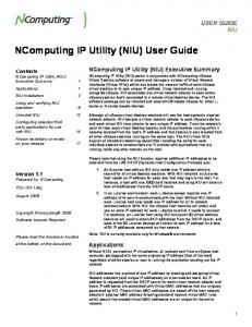
3.3.2.2 EPI Data Set Generator
1
2
3
4
5
6
The 'EPI Data Set Generator' module allows the creation of new EPI panel data sets for OEM panels either from scratch or based on one of the congatec standard EPI data sets. The fields in block 1 have no direct technical meaning and can be set as desired (as much as possible due to format and field size limitations). Nevertheless, they should be filled with reasonable data as they may help to organize and identify different data sets. congatec uses the 'Product/Data Set ID' field to uniquely identify a certain released EPI data set. To avoid confusion with congatec defined data set IDs, it is recommend for customers to use IDs above 0FFh for their own EPI panel data sets. The fields in block 2 define the resolution and the timing parameters for a certain panel. These values can be derived from the respective panel datasheet. The synchronization signal polarities can be defined by the fields in block 3. The respective values are either defined in the panel's datasheet or must be selected according to the actual hardware design. The fields in block 4 define basic technology parameters of the selected panel and have
Copyright © 2006 congatec AG
CGUTILm14
23/48
to be set accordingly. Block 5 contains fields to define backlight and contrast control values within the EPI data set as well as the desired image orientation. Finally, block 6 offers fields to define power on/off sequencing delay values in the EPI data set. Usage of this module is described in detail in the standalone congatec application note AN12_Modify_EPI_Files. Refer to this document for further information.
3.3.3
Command Line Versions Function module selector: CPANEL Syntax: CGUTLCMD CPANEL /OT:[target] /[command] [PARM] /OT:
Specify the operating target. BOARD: All actions result in direct hardware accesses to the respective congatec board. All other strings are interpreted as name of the BIOS ROM file to be modified.
PARM
Command parameter, if required (e.g. filename of data file).
Commands: /SEPI
Find congatec EPI module and save it to a file specified by PARM.
/LEPI
Add or replace the complete congatec EPI module. PARM must specify the name of a valid congatec EPI module file.
/SSTD:xxx
Find standard EPI data set number xxx (hexadecimal) in the BIOS and save it to a file specified by PARM.
/SOEM:xxx
Find OEM EPI data set number xxx (hexadecimal) in the BIOS and save it to a file specified by PARM.
/LOEM :xxx
Add or replace OEM EPI or EDID™ 1.3 panel data set number xxx (hexadecimal). PARM must be set to the name of a valid EPI or EDID™ 1.3 panel data file.
/DOEM:xxx
Delete OEM EPI or 1.3 panel data set number xxx (hexadecimal).
/SEEP
Read panel data set stored in the EPI EEPROM and save it to a file specified by PARM. This function is only available in 'Board' mode.
/LEEP
Write data to congatec EPI EEPROM. PARM must be set to the name of a valid panel data set file.
Copyright © 2006 congatec AG
CGUTILm14
24/48
This function is only available in 'Board' mode. /CEEP
Clear the EPI EEPROM. This function is only available in 'Board' mode.
/SBLV
Set control value of a backlight intensity control device on the EPI I2C bus. (PARM: 0-100; value in percent of maximum value). This function is only available in 'Board' mode.
/GBLV
Get current value of backlight intensity control device on the EPI I2C bus. (Value returned in percent of maximum value). This function is only available in 'Board' mode.
/SBLS
Set backlight enable state (PARM:0=OFF 1=ON). This function is only available in 'Board' mode.
/GBLS
Get backlight enable state (0: OFF 1: ON). This function is only available in 'Board' mode.
/DPL
Display list of EPI data sets included in the BIOS.
Note When the 'BIOS Update And Write Protection' feature is enabled in BIOS setup, commands that try to write to the BIOS flash will fail. In order to deactivate the BIOS write protection until next boot use: 'CGUTLCMD BFLASH /BP:[password]'
Copyright © 2006 congatec AG
CGUTILm14
25/48
3.4 3.4.1
BIOS Module Modification Module General Description The congatec system BIOS offers support for several OEM defined add-on BIOS modules. Each congatec BIOS includes a flash storage area called the Multi Purpose Flash Area (MPFA) where these add-on modules, along with predefined congatec standard modules, can be stored. Modules located in this area consist of a MPFA header for organization purposes and the actual module data defined and provided by the OEM or predefined by congatec. The standard system BIOS includes routines to handle different MPFA module types. The BIOS identifies the respective module by evaluating the module type field in the MPFA header of the module and executes the appropriate function for this module type during POST. All modules use at least the module type, module ID and module revision fields of the MPFA module header. If different modules of a certain type are to be added to the BIOS, these modules must have different module IDs in order to be differentiated. The module revision field is for information purposes only, in order to keep track of module versions. Depending on the module type, additional information put into the module header might be required to handle the respective module. If this is the case, it will be noted in the following module descriptions. The congatec System Utility provides functions to create, add, replace, save and delete the BIOS add-on modules, extract module data and generate a report of all currently included modules. Adding or deleting BIOS modules obviously means that the standard congatec BIOS is modified (either a BIOS ROM file if working in 'ROM File' mode, or the BIOS stored in the onboard Flash Memory chip if working in 'Board' mode). In order to distinguish an OEM modified BIOS from the standard congatec BIOS version that it is based on, the utility also allows you to assign an OEM BIOS version to the modified BIOS. This OEM version will be displayed during POST and in the setup menu in addition to the standard BIOS version. Note All functions of the BIOS Module Modification Module are supported when the congatec System Utility is in 'Board' and 'ROM-File' mode.
Copyright © 2006 congatec AG
CGUTILm14
26/48
3.4.2
BIOS Module Types
3.4.2.1 CMOS Backup Map BIOS Module This module contains a backup copy of the current CMOS settings. It is generated automatically by the BIOS when leaving the setup using the 'Save and Exit' option. During the next boot, the CMOS values stored in this module are copied back to CMOS RAM in the RTC. Thus, RTC power loss will not lead to loss of CMOS setup settings. Moreover, by reading the automatically generated CMOS backup map module from a certain board and deploying it to other boards of the same kind using this utility, OEMs can easily clone setup configurations. Only backup maps created for the same board and BIOS version can be added, everything else will be rejected by the utility. Currently one CMOS backup map module is supported. The module ID parameter is reserved for future usage and must always be set to zero or 0xFF for now.
3.4.2.2 CMOS Default Map BIOS Module This module can be used to override the build time defined CMOS default values of a congatec BIOS. If a valid CMOS default map module is found by the respective BIOS module handler then the values stored within this module will be used as CMOS default values, instead of the build time defined standard CMOS default values, whenever the CMOS is set back to defaults (e.g. when loading setup defaults in the BIOS setup menu). The easiest way to create an OEM specific CMOS default map is to configure a certain congatec board to the settings required as default values and leave the setup menu using the 'Save and Exit' option. The BIOS will automatically create a CMOS backup map module using the configured values. In order to generate a CMOS default map module, the generated CMOS backup map module must be loaded as an input data file to generate a CMOS default map module. The default map module in turn can be added to all target boards and will be used as OEM specific CMOS default value map. In order to go back to the original build time defined CMOS default values, the OEM CMOS default map module simply must be deleted. Only default maps created for the same board and BIOS version can be added, everything else will be rejected by the utility. A standard congatec BIOS only supports one active CMOS default map module. The module ID parameter for this module must always be set to zero. Support for more than one default map module in the same BIOS is possible but requires a special module selection OEM code BIOS module. Refer to the congatec application note AN8_Create_OEM_Default_Map for detailed information about how to create and add an OEM default map.
Copyright © 2006 congatec AG
CGUTILm14
27/48
3.4.2.3 OEM Setup BIOS Module This module can be used to override the build time defined setup menu of a congatec BIOS. If a valid OEM setup module is found by the respective BIOS module handler, the setup menu layout stored within this module will be used instead of the build time defined standard setup menu. An OEM setup module can be created using the BIOS Setup Configuration module of the congatec System Utility. The OEM setup module in turn can be added to all target boards and will be used as OEM specific setup menu. In order to go back to the original build time defined setup menu, the OEM setup module simply must be deleted. Only OEM setup modules created for the same board and BIOS version can be added, everything else will be rejected by the utility. A standard congatec BIOS only supports one active OEM setup module. The module ID parameter for this module must always be set to zero. Support for more than one OEM setup module in the same BIOS is possible but requires a special module selection OEM code BIOS module. Refer to the description of the BIOS Setup Configuration module in this document and to the congatec application note AN10_BIOS_Setup_Configuration for detailed information about how to create and add an OEM setup module.
3.4.2.4 OEM String Table BIOS Module This module type is reserved for future use only.
3.4.2.5 Fixed CMOS Map BIOS Module This module type is reserved for future use only.
Copyright © 2006 congatec AG
CGUTILm14
28/48
3.4.2.6 Boot Logo BIOS Module The congatec system BIOS includes support to display OEM defined BIOS boot logos during POST. The congatec system utility allows you to create OEM logo modules and add them to the system BIOS. On AMIBIOS based products, JPEG files can be used as input for OEM logo modules. However, not every kind of JPEG or every feature of a JPEG is supported. JPEG images that cannot be displayed by the BIOS will be rejected by the utility. For products based on the Insyde XpressROM BIOS, a more complex input logo file is used that requires special preprocessing. The description for this process is beyond the scope of this document but can be found in the congatec application note AN11_Create_And_Add_Bootlogo. Even though an OEM logo module can be added to the BIOS by the utility, it will not be activated automatically. Refer to the user's guide of the respective congatec board, or to AN11_Create_And_Add_Bootlogo for information about how to activate boot logo display. A standard congatec BIOS only supports one active OEM logo module. The module ID parameter for this module must always be set to zero. Support for more than one OEM logo module in the same BIOS is possible but requires a special module selection OEM code BIOS module. Note AMIBIOS BOOT logo features and limitations: The boot logo can be displayed in VESA mode 112h, 111h, 110h (640X480), 115h, 114h, 113h (800X600), 118h, 117h, 116h (1024X768), 11Bh, 11Ah, 119h (1280X1024). The video mode will be selected automatically depending on the image resolution. The video BIOS, as well as the display device, should support the appropriate resolution otherwise the result is unpredictable. The following must be considered when a JPEG image is used as a boot logo: •
Extended sequential DCT is not supported.
•
Define restart interval (DRI) is not supported.
•
Progressive encoding is not supported.
•
Lossless sequential encoding is not supported.
•
Differential sequential DCT is not supported.
•
Differential progressive DCT is not supported.
•
The X-density/Y-density should be 1:1.
Copyright © 2006 congatec AG
CGUTILm14
29/48
•
YUV111 and YUV112 (color component 1:1:2 and 1:1:1) is supported.
•
IPTC or EXIF information blocks (additional textual information, like title, copyrights, date, time, ...) cannot be included.
Unfortunately, especially JPEG files created by digital cameras or created with Adobe Photoshop use a lot of these unsupported features and in particularly add the IPTC or EXIF information block. Thus, a JPEG image that is to be used as a boot logo must always be checked before being added to the BIOS. The following tools may be used to generate or modify the JPEG file: - IrfanView ( freeware) - ACDSee 2.41 or 3.0 - PaintShop
3.4.2.7 EPI Panel Data BIOS Module As described in the Panel Configuration Module section earlier, all congatec boards support the EDID™ 1.3 based EPI (Embedded Panel Interface) specification for configuration of local flat panels. The congatec system BIOS includes a table of predefined and validated EPI data sets for standard panels. These panel data sets, as well as placeholders for OEM defined panel data sets, are included in the EPI BIOS module, which is one of the predefined modules stored in the MPFA area. This module is required for fixed panel type selection via the BIOS setup menu. It is listed here for completeness only and should never be modified or deleted using the BIOS Module Modification Module of the congatec System Utility.
3.4.2.8 OEM Code/Data BIOS Module OEM BIOS modules can be used to add OEM defined data or code blocks to the standard system BIOS. By setting the load time, execution time and load address values within the MPFA header, OEMs can define when the respective module should be loaded to RAM and executed during BIOS POST. OEM BIOS code modules may be used to perform custom specific hardware initialization, pre-boot software checks, user authentication or even skip parts of the standard BIOS boot process and create own boot loaders. Any number of OEM BIOS modules can be added to the system BIOS as long as there is enough space left in the MPFA. However, if more than one OEM BIOS module should be used, each module must be given a unique module ID in the MPFA header. In a case where an OEM BIOS module is added whose module ID is the same as the ID of an already existing OEM BIOS module, the existing module will be replaced by the new one without special notification. In addition to module type, module ID and module revision that must be configured for any BIOS add-on module in the MPFA header, several other MPFA fields must be set for OEM BIOS modules as well:
Copyright © 2006 congatec AG
CGUTILm14
30/48
1. Load and Execution Time Load and execution time fields define at which point during BIOS POST the OEM module should be copied to RAM and executed. The following load and start time hooks are supported: NONE
Do not load/execute the OEM module.
Choosing one of the load times listed below and using NONE as an execution time, can be used to load an OEM data block to the upper memory area and keep it there to be used by an OS application.
BEFORE_CMOS_TEST
Load/execute before CMOS test.
On AMIBIOS based products, this is one of the first hooks of the main BIOS (i.e. bootblock execution has just been finished). Only basic chipset and memory initialization has been performed at this point in time. PCI and Super I/O devices are not yet configured and none of the standard BIOS runtime interfaces are available. OEM code executed at this point should only be developed in close cooperation with congatec.
BEFORE_VIDEO_INIT
Load/execute before video BIOS initialization
Hardware resources have been assigned to video and other output devices. Final video and output device configuration will follow immediately after this point.
AFTER_VIDEO_INIT
Load/execute after video BIOS initialization.
Video and other output devices are fully initialized and configured. At this point the video BIOS INT10h interface becomes available.
BEFORE_OPROM_SCAN Load/execute before option ROM scan. Hardware resources have been assigned to all PCI devices. All Super I/O devices are initialized.
AFTER_OPROM_SCAN
Load/execute after option ROM scan.
At this point all PCI and Super I/O devices are fully initialized and configured. Mass storage devices have been detected and configured. All BIOS runtime services are available. All option ROMs have been initialized.
BEFORE_SETUP
Load/execute on setup screen start.
OEM code using this hook will be executed when the setup screen is started.
SETUP_EXTENSION
Load/execute as setup screen extension.
In case an OEM module is defined with this load and execution point, an additional setup node 'OEM Setup Utility' will be displayed in the setup screen. When selected, the respective OEM code is executed, e.g. to configure special hardware.
BEFORE_BOOT
Load/execute at end of BIOS POST.
Every BIOS initialization task has been performed at this point and every BIOS runtime interface is available. The only thing that remains to be done is to search the detected boot devices for an
Copyright © 2006 congatec AG
CGUTILm14
31/48
OS loader and start the OS. Recommended execution point for an OEM defined OS loader.
The above load and execution time hooks are given in the order they are executed during BIOS POST. It makes no sense to set the load time later than the execution time, such a configuration will be rejected by the congatec System Utility. 2. Load Address The load address field defines the physical memory address the OEM module should be copied to. Setting a fixed load address is possible but might be difficult to handle as the OEM may not know which memory ranges are not already used by parts of the BIOS. Therefore it is recommended to use the the following special address selectors instead of 'real', fixed addresses. 00000000h
Load module at any free upper memory block address (640k...1MB).
FFFFFFFEh Load module at any free conventional memory address (0k...640k). FFFFFFFFh Load module at any free extended memory address (above 1MB). Note The standard BIOS may clear conventional RAM prior to OS boot. Moreover, operating systems may also clear the conventional as well as the extended memory area during startup. Therefore, OEM code loaded to these areas may not be available anymore after the OS starts. 3. Entry Offset The entry offset field specifies the location within the OEM code block relative to the start of the block. The BIOS OEM code handler jumps to this location within the OEM module to start execution. Only the offset to the start of the OEM defined data block must be specified; the additional offset due to the MPFA header generated by the congatec System Utility will be calculated by the BIOS OEM code handler. Note The BIOS OEM code handler is a very simple and limited execution engine. It only copies the OEM code block to the given load address in RAM at the specified time during POST and performs a far call to the defined entry offset. Any sort of standard executable header will not be evaluated. Throughout the BIOS POST the so called big real mode is used. This means that only real mode code execution is natively supported. Flat mode memory data accesses are possible using the ES and DS segment/selector registers set to zero. Any sort of protected mode code can only be executed if the OEM code block performs the required initialization in the code part starting at the specified entry offset. The OEM code can return to the standard BIOS POST flow by performing a far return. However, this can only be successful if the memory model is unchanged, the stack is cleaned up and all registers are restored to original values. Simple real mode COM style executables or real mode option ROM like code blocks are best suited to be included as OEM code modules.
Copyright © 2006 congatec AG
CGUTILm14
32/48
Caution The congatec System Utility cannot perform any sort of validity check on OEM BIOS code modules. If a corrupt OEM code module is added and executed during BIOS POST, the system may not boot anymore. Therefore, it should be considered as mandatory to prepare a backup copy of the original system BIOS on an external Flash Memory chip when testing OEM code modules. Adding own code to the BIOS can never be considered a trivial process. Therefore at least the initial steps, especially the selection of the appropriate load and execution times, should always be performed in cooperation with congatec.
3.4.2.9 OEM Video Mode Module Recent congatec system BIOS versions for all Intel chipset based congatec products include support to add additional OEM defined video modes to the standard video modes already offered by the video BIOS. The generic VESA frame buffer graphics drivers, the Intel GMA graphics drivers for Windows operating systems and the i810/i910 Linux graphics drivers, will also add these OEM video modes to their lists of supported video modes and resolutions. This feature is required in order to make the best use of a display offering a special resolution that by default is not supported by the video BIOS or previously mentioned graphics drivers. In order to create an OEM video mode module, a valid EDID™ 1.3 or EPI data set (e.g. created using the EPI Data Set Generator) must be loaded as an input data file. Up to four OEM video mode modules (and thus up to four OEM video modes) can be added to the BIOS and are identified by the 'Module ID' parameter. The OEM video modes will be assigned the following video mode numbers: 1. Module ID = 0 8 bpp = VGA mode 60h / VESA mode 160h 16 bpp = VGA mode 61h / VESA mode 161h 32 bpp = VGA mode 62h / VESA mode 162h 2. Module ID = 1 8 bpp = VGA mode 62h / VESA mode 163h 16 bpp = VGA mode 64h / VESA mode 164h 32 bpp = VGA mode 65h / VESA mode 165h 3. Module ID = 2 8 bpp = VGA mode 66h / VESA mode 166h 16 bpp = VGA mode 67h / VESA mode 167h
Copyright © 2006 congatec AG
CGUTILm14
33/48
32 bpp = VGA mode 68h / VESA mode 168h 4. Module ID = 3 8 bpp = VGA mode 69h / VESA mode 169h 16 bpp = VGA mode 6Ah / VESA mode 16Ah 32 bpp = VGA mode 6Bh / VESA mode 16Bh Note For special resolution local flat panels or SDVO local flat panels, no additional OEM video mode module needs to be added in order to get support for the respective special video mode and resolution. The BIOS code will automatically add a corresponding OEM video mode for the panel deriving the required data directly from the EPI data set used for physical panel adaption. These automatically added OEM video modes will be assigned the following video mode numbers: 1. Local Flat Panel 8 bpp = VGA mode 6Fh / VESA mode 16Fh 16 bpp = VGA mode 70h / VESA mode 170h 32 bpp = VGA mode 71h / VESA mode 171h 2. SDVO Local Flat Panel 8 bpp = VGA mode 6Ch / VESA mode 16Ch 16 bpp = VGA mode 6Dh / VESA mode 16Dh 32 bpp = VGA mode 6Eh / VESA mode 16Eh
3.4.2.10 OEM HDA Verb Table Module This module can be used to add OEM specific initialization tables for High Definition Audio Codecs to congatec system BIOS versions offering support for OEM HDA configuration. Detailed description of this feature and the required input data for this sort of module is beyond the scope of this document. Contact congatec technical support for more information about customized HDA codec initialization.
Copyright © 2006 congatec AG
CGUTILm14
34/48
3.4.3
Windows GUI Version
Available functions: [Add Module] Add a congatec BIOS module to the operating target. [Delete Module] Delete the module selected in the 'Current congatec BIOS Modules' window. [Save Module To File] Save the BIOS module selected in the 'Current congatec BIOS Modules' window. This will save the whole module, i.e. the actual module data as well as the module's MPFA header. [Save Module Data To File] Save the data of the module (without MPFA module header) selected in the 'Current congatec BIOS Modules' window to a file.
Copyright © 2006 congatec AG
CGUTILm14
35/48
[Save Module Overview] Generates a list of all currently included BIOS MPFA modules and saves it to a file. [Create Module] The first click on this button will initiate the module creation process by asking the user to select a file containing the data that should be included in the module. After loading the module data file, the desired module type must be selected in the module type parameter field. Make sure that the module ID field is set according to the module description above and set the desired module revision. If the selected module type is 'OEM Code/Data', the additional parameter fields load time, execution time, load address and entry offset also must be configured and therefore become selectable. When all parameters are configured, click CREATE again to generate and save the created module to a file. This module file in turn can be added using the Add Module function. [Deactivate BIOS Write Protection] This function is only available and required in 'Board' mode and only if the 'BIOS Update And Write Protection' feature is available and activated in the current BIOS. In this case write and erase accesses to the target's Flash Memory chip and therefore all BIOS modifications in 'Board' mode are only possible after temporarily deactivating the protection. This can be done by passing the correct deactivation password using the dialog started with this button. All actions of this function module are first performed on a temporary buffer and can be undone anytime by clicking the 'Cancel' button. Only after clicking the 'Apply' button is the selected operating target actually modified. The top left section of the window provides an overview of the currently contained modules in the MPFA and informs you about the space left in the storage area. Selecting one of the displayed module entries updates the module parameter field with the parameters of this module. The output window below the module parameter field is used to display additional information, error and operation progress messages. At the top of the window the original congatec BIOS version and the OEM BIOS version of the current operating target are displayed. The congatec version field is included for reference purposes only and cannot be modified. The OEM BIOS version field can and should be used to assign an up to eight character add-on OEM BIOS version string to the modified BIOS. As long as no OEM version is assigned, this field will be blank. To assign an OEM version to the BIOS, simply enter the desired string in the field and press the 'Apply' button. The respective OEM version string will be displayed together with the standard BIOS version in the BIOS setup screen and on the BIOS boot screen. If a BIOS is modified by adding or deleting a BIOS module, but no dedicated OEM version is assigned, the add-on version information would still be displayed in the setup screen or on the BIOS boot screen. However, in this case the OEM version would be set to 'UNKNOWN'. To avoid this, it is highly recommended to always set a defined OEM version string when modifying the BIOS and use that same OEM version string to name the OEM BIOS version file.
Copyright © 2006 congatec AG
CGUTILm14
36/48
Note A CMOS default map module can only be generated out of a valid CMOS backup map module file as an input file. The CMOS default map module cannot be generated using the data of the CMOS backup map module only. This is a special case of module creation for the CMOS default map to ensure that a default map can only be generated out of data for the same BIOS version. The CMOS backup map module still includes information about the BIOS that the backup map has been derived from. The pure module data would not contain this information anymore. Thus, the respective information couldn't be added to the default map module. A default map module with invalid or non existing BIOS information however would be rejected by the Add Module function. Example: Create and add a BIOS boot logo module. 1. Initiate the module creation process by clicking the 'Create Module' button and select a valid JPEG data file.
Copyright © 2006 congatec AG
CGUTILm14
37/48
2. Select the 'BIOS Boot Logo' module type, ensure that module ID is set to zero and enter a module revision if desired. Afterwards, click 'Create Module' button again to generate and save the module.
Copyright © 2006 congatec AG
CGUTILm14
38/48
3. Click 'Add Module' and select the recently created boot logo module file. The logo module should now be displayed in the 'Current congatec BIOS Modules' window. Select it and verify that the module parameters are correct.
4. Set a defined OEM version in the OEM BIOS Version field and click the 'Apply' button to update the operating target.
Copyright © 2006 congatec AG
CGUTILm14
39/48
3.4.4
Command Line Versions Function module selector: MODULE Syntax: CGUTLCMD MODULE /OT:[target] /[command] /OF: /IF: [PARMS]
/OT:
Specify the operating target. BOARD: All actions result in direct hardware accesses to the respective congatec board. All other strings are interpreted as name of the BIOS ROM file to be modified.
PARMS
Command parameters, if required (see below).
/IF:
Specify the input data file (depends on command).
/OF:
Specify the output data file (depends on command).
Commands: /SAVE
Find specified module and save it to the output data file.
/DSAVE
Find specified module and save its data block.
/CMP
Find specified BIOS module and compare it with the module input file.
/DCMP
Find specified BIOS module and compare module data with the data part of the module input file.
/DEL
Find specified module and delete it.
/ADD
Add a new BIOS module specified with the input file parameter to the operating target.
/LIST
Generate a list of all congatec BIOS modules found on the operating target and display it.
/SLIST
Generate a list of all congatec BIOS modules found on the operating target and save it to the output data file.
/CREATE
Create a new congatec BIOS module using input file data and store the result in the specified output file.
/INFO
Display the OEM BIOS version (if assigned) and information about the free space left in the module storage area.
/OEM:xxxxxxxx
Assign an OEM BIOS version (max. eight characters). This OEM BIOS version will be displayed in addition to the original congatec BIOS version in BIOS setup and during POST.
Copyright © 2006 congatec AG
CGUTILm14
40/48
congatec BIOS Module Parameters: /T:
BIOS module type (BYTE).
/ID:
BIOS module ID (WORD). Default: 0
/R:
BIOS module revision (BYTE). Default: 0
/LA:
BIOS module physical load address (DWORD, usercode only). Default: 0 Special addresses: 00000000: Load module at any free upper memory block address. FFFFFFFE: Load module at any free conventional memory address. FFFFFFFF: Load module at any free extended memory address.
/LT:
BIOS module load time (BYTE, user code only).Default: 0
/ET:
BIOS module execution time (BYTE, user code only).Default: 0
/O:
BIOS module entry offset (DWORD, user code only).Default: 0
congatec BIOS Module Types: 1
CMOS Backup Map Module
2
CMOS Default Map Module
3
OEM Code/Data Module
5
EPI Panel Data Module
6
BIOS Boot Logo Module
8
OEM Setup Module
9
Fixed CMOS Map Module
A
OEM String Table Module
B
OEM Video Mode Module
C
OEM HDA Verb Table Module
congatec Execution/Load Time Selectors: 0
NONE
Do not load/execute the OEM module.
2
BEFORE_CMOS_TEST
Load/execute before CMOS test.
Copyright © 2006 congatec AG
CGUTILm14
41/48
3
BEFORE_VIDEO_INIT
Load/execute before video BIOS initialization.
4
AFTER_VIDEO_INIT
Load/execute after video BIOS initialization.
5
BEFORE_OPROM_SCAN
Load/execute before option ROM scan.
6
AFTER_OPROM_SCAN
Load/execute after option ROM scan.
7
BEFORE_SETUP
Load/execute on setup screen start.
8
SETUP_EXTENSION
Load/execute as setup screen extension.
9
BEFORE_BOOT
Load/execute at end of BIOS POST.
All numeric parameters are interpreted as hexadecimals. Notes The /DEL, /SAVE and /DSAVE commands require, at the very least, that a module type is specified. If there are more modules of this type, the first found module will be chosen. For a unique identification, the module ID parameter also has to be passed. Anytime a BIOS module is added to or deleted from a standard congatec BIOS, it will result in the BIOS displaying an add-on OEM version information string to the BIOS boot screen and in the BIOS setup menu. If no defined OEM version is assigned using the /OEM: command, the OEM version would be set to 'UNKNOWN'. To avoid this, it is highly recommended to always set a defined OEM version string when modifying the BIOS and use that same OEM version string to name the OEM BIOS version file. Examples 1. Deleting a BIOS boot logo module in 'Board' mode. CGUTLCMD MODULE /OT:BOARD /DEL /T:6 2. Saving a Backup map module to a file in 'Board' mode. CGUTLCMD MODULE /OT:BOARD /SAVE /OF:BACKUP.MOD /T:1 3. Creating a default map module out of the backup map module. CGUTLCMD MODULE /OT:BOARD /CREATE /IF:BACKUP.MOD /OF:DEFAULT.MOD /T:2 /ID:0 /R:1 4. Adding the default map module to a BIOS ROM file in 'ROM File' mode. CGUTLCMD MODULE /OT:P915R111.ROM /ADD /IF:DEFAULT.MOD 5. Delete OEM module with module ID 2. CGUTLCMD MODULE /OT:BOARD /DEL /T:3 /ID:2
Copyright © 2006 congatec AG
CGUTILm14
42/48
6. Assign a defined OEM version to the modified BIOS. CGUTLCMD MODULE /OT:BOARD /OEM:OEMVR001 or in ROM file mode: CGUTLCMD MODULE /OT:P915R111.ROM /OEM:OEMVR001
3.5 3.5.1
Board And BIOS Information Module General Description This module offers an easy way to gather relevant information about a certain congatec board and BIOS. The information is meant to be used by customers during their own setup or manufacturing process to identify a congatec board or BIOS, or to be passed to congatec when contacting the support team. The following information can be derived from a congatec board: •
System BIOS Version
•
OEM BIOS Version
•
Board Controller Firmware Version
•
Board Name
•
Board Sub Name
•
Product Revision
•
Part Number
•
EAN Code
•
Serial Number
•
Manufacturing Date
•
Last Repair Date
•
Boot Counter
•
Running Time
•
CGOS API Version
•
CGOS Driver Version
•
BIOS Update And Write Protection State
The information module can also be used in 'ROM File' mode, i.e. to analyze a congatec
Copyright © 2006 congatec AG
CGUTILm14
43/48
BIOS file. From this BIOS file however only the system and OEM BIOS version can be derived.
3.5.2
Windows GUI Version
When started the Windows GUI version of the Board And BIOS Information module automatically gathers and displays all available board information, which can also be saved to a simple text file.
3.5.3
Command Line Versions Function module selector: CGINFO Syntax: CGUTLCMD CGINFO /OT:[target] /[command] [parm] [options]
/OT:
Specify the operating target. BOARD: All actions result in direct hardware accesses to the respective congatec board. All other strings are interpreted as name of the BIOS ROM file to be analyzed.
parm
Command parameter, if required (e.g. input or output file name).
options
Information selection option(s). One or more options to select the information that should be returned by the DUMP or SAVE command (see below).
Copyright © 2006 congatec AG
CGUTILm14
44/48
Commands: /SAVE
Save selected information to file.
/DUMP
Display selected information on screen.
/BFCHK
Check whether the operating target system and OEM BIOS versions match the versions of the specified BIOS file.
Information selection options: /SILENT
Information is displayed or saved without description text (e.g.: 'X945R111' instead of 'System BIOS Version: X945R111').
/BIOS
Return system and OEM BIOS version.
/BCFW
Return board controller firmware version.
/CGOS
Return CGOS interface and driver version.
/BCNT
Return boot counter.
/RTIM
Return running time.
/MANU
Return CPU-board manufacturing data.
/BUP
Return state of the 'BIOS Update And Write Protection'
If no selection options are passed, the complete information list will be displayed or saved.
Examples 1. Display BIOS versions and boot counter with description text. CGUTLCMD CGINFO /OT:BOARD /DUMP /BIOS /BCNT Possible output: System BIOS Version: OEM BIOS Version: Boot Counter:
Copyright © 2006 congatec AG
X945R111 26
CGUTILm14
45/48
2. Display board manufacturing information with description text. CGUTLCMD CGINFO /OT:BOARD /DUMP /MANU Possible output: Board Name: Board Sub Name: Product Revision: Part Number: EAN Code: Manufacturing Date: Last Repair Date:
3.6 3.6.1
P915 P915 E.0 (0x4530) 098636 0425018610568 2006.08.14 0000.00.00
BIOS Setup Configuration Module General Description The BIOS Setup Configuration module offers functions to customize the standard, build time defined BIOS setup menu of a congatec BIOS. The new setup menu can directly be added to the operating target BIOS or saved as an OEM setup module file to be added to systems later on. The module provides the ability to hide unwanted setup nodes completely, set user access rights for some or all nodes and limit the available selection options for certain simple nodes. It is not possible to add new setup nodes or modify the text related to an existing setup node. Note This module is currently only supported for AMIBIOS based congatec boards.
Copyright © 2006 congatec AG
CGUTILm14
46/48
3.6.2
Windows GUI Version
Input Data Block In this area you can select the setup menu and the default map to be used for the BIOS Setup Node Tree window. In an unmodified standard congatec BIOS only the 'Original System BIOS Setup' and the 'Original System BIOS Defaults' can be selected. However, as soon as an OEM setup module or an OEM CMOS default map module is included in the BIOS, the respective module can be selected as well.
Copyright © 2006 congatec AG
CGUTILm14
47/48
Generate New Setup Module This area offers the required functions to add the modified setup menu to the BIOS or save it as an OEM setup module file. The module ID for the new OEM setup module in general always has to be set to zero. Only in this case the new setup menu will automatically be used by the BIOS. Other IDs are only meant to be used in case more than one OEM setup module should be added to the same BIOS. However, this would also require a special setup module selection OEM code module. This is a special topic that is beyond the scope of this document. If more information about handling more than one OEM setup module in the same BIOS is required, contact the congatec technical support team. BIOS Setup Node Tree The window in this area is used to display all available setup nodes of the operating target BIOS. Selected nodes in this window can be modified using the functions in the Modify BIOS Setup Node group. Modified nodes will be highlighted. Note The setup menu layout presented in the BIOS Setup Node Tree window will probably differ from the setup menu seen when starting the setup program on a real board. In fact you will always see more nodes and menus in the utility's setup window than you would see when starting the setup on a board. This is due to the fact that the utility displays ALL nodes and menus defined in the BIOS at build time. When executing the setup on a board, the visibility of several nodes and menus is defined by code executed on this board when the setup menu is started. For several nodes this code 'decides' that they should not be displayed on the setup screen (e.g. nodes to control the SpeedStep settings will never be displayed on a board equipped with a Celeron M CPU that does not support this feature). Since the utility is unable to execute this 'display decision' code, all available and possible nodes are displayed. This might be slightly confusing but the worst thing that could happen would be that a node is modified using the utility although this node would never be displayed by the 'real' setup on a board anyway. Modify BIOS Setup Node This area offers functions to hide nodes, change the required user access rights for nodes in case a setup supervisor password is installed or limit the selection possibilities for certain nodes. The area at the bottom of the BIOS Setup Configuration module can be used to display or save a list of differences between OEM and standard system BIOS default settings or between OEM and standard system BIOS setup layout. This functionality is mainly meant for congatec internal usage, as the full interpretation of the result requires additional information that cannot be passed to customers. Refer to the congatec application note AN10_BIOS_Setup_Configuration for detailed information about the setup configuration module of the congatec System Utility.
Copyright © 2006 congatec AG
CGUTILm14
48/48