network designers to choose the appropriate omega network architecture to control the congestion. KEYWORDS. Omega network, congestion control, buffer size ...
IADIS International Conference on Applied Computing 2005
CONGESTION CONTROL BY USING A BUFFERED OMEGA NETWORK Ahmad .H. ALqerem Dept. of Comp. Science – ZPU Zarka Private University Zarka – Jordan
ABSTRACT Omega networks are used to connect processors and memory in large scalable multiprocessor systems. In this paper we use the omega network to connect the LANs to each other. Routers are used instead of switching elements. Buffers are used inside the routers to increase the throughput of the omega network and to prevent the internal loss of packets. The objective of this paper is to control the congestion by using a buffered omega network. This reflects the situation in an ATM environment where all packets (cells) have a fixed length. The results obtained from the study will help the network designers to choose the appropriate omega network architecture to control the congestion. KEYWORDS Omega network, congestion control, buffer size, number of LANs, time duration.
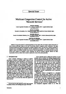
1. INTRODUCTION Congestion can be characterized by the presence of a large number of packets (load) being routed in all or portions of the subnet that exceeds its link and router capacities (resources) resulting in a performance slowdown [1]. All solutions are divided into two groups, open loop and closed loop. An open loop solution involves: • Deciding when to accept new traffic • Deciding when to discard packets and which ones • Making scheduling changes at various points on the network. Solve the problem by good design - make sure congestion does not happen in the first place. Closed loop solutions are based on a feedback loop [1]: • Monitor the system to detect when and where congestion occurs. • Pass the information on to places where action can be taken. • Adjust system operation to correct the problem. This paper introduces a new technique or method for controlling the congestion in virtual circuit subnets, by using Omega Networks, which can be classified as open loop system. Omega network is used to connect a large number of processors with memory [2], but in this paper using the omega networks to connect the router with each others. Omega networks can be classified into two main categories, namely internally blocking and internally nonblocking [3]. In an internally nonblocking if given a permutation of two or more packets at its input it can route all these packets through the network without contention or collisions. An omega network is called internally blocking if two or more packets with distinct output port destination can’t always be transferred to the output ports due to routing conflict within the omega network [2]. The contention occurs in omega network when more than one packet accesses the same internal link. Figure 1 shows the internal blocking in a certain router inside the omega network.
429
ISBN: 972-99353-6-X © 2005 IADIS
Figure 1. Internally blocking.
Each router has two buffers, with fixed lengths; packets are queued in those buffers until they can be forwarded to the next stage. They are implemented by using first-in-first-out (FIFO) queues. The aim of this paper is to study the performance of omega network with local fixed buffer lengths in order to reduce the congestion if it will occur. The simulator has the ability to test and counts all the packets the are generated, delivered, and discarded in different omega network shapes, the shape of omega network can be formatted by choosing number of stages in omega network, running time duration, number of simultaneous sending LANs, and buffer length or size. The paper is organized as follows: In section 2, omega network structure and behavior. In section 3, the simulator model. In section 4, experimental results. In section 5, the conclusion.
2. STRUCTURE AND BEHAVIOR OF OMEGA NETWORK The general schematic of omega network consisting of N input and M output is shown in Figure 2. input
output 0
0 stage 3
stage 2
Stage 1
1
1
M-1
N-1
Figure 2. The schematic of a typical Omega
This network consists of log N stages (where N is the number of input and also the number of output). Each stage of the omega network consists of an interconnection pattern that connects N inputs and M outputs, a link exists between input i and output j if the following is true: -
2i
J=
2i + 1 – N ,
,
0 ≤ i ≤ N /2 -1 N/2 ≤ I ≤ N - 1
Equation 1 representation a left-rotation operation on the binary representation of i to obtain j. this interconnection pattern is called a perfect shuffle. Figure 3 shows a perfect shuffle interconnection pattern for eight inputs and outputs. In each stage of an omega network, a perfect shuffle interconnection pattern feeds into a set of N/2 switching elements. Each switch is in one of two connection modes. In one mode, the inputs are sent straight through to the outputs, as shown in Figure 4(a). This is called the pass-through connection. In the other mode, the inputs to the switching element are crossed over and then sent out, as shown in Figure 4(b). This is called the cross-over connection.
430
IADIS International Conference on Applied Computing 2005
000
0
0 000
001
1
1 001
010
2
2 010
011
3
3 011
100
4
4 100
101
5
5 101
110
6
6 110
111
7
7 111
Figure 3. A perfect shuffle interconnection for eight input and outputs.
An omega network has N/2 × log N switching elements, and the cost of such a network grows as Θ (N log N).
(a)
(b)
Figure 4. Two switching configuration of the 2*2 switch (a) pass-through; (b) Cross-over
Figure 5 shows an omega network for eight input. Input nodes of the network and the output nodes. Routing messages in an omega network is accomplished by using a simple scheme. Let s and t be the binary representations of the source and destination of the message. The message traverses the link to the first router. If the most significant bits of s and t are the same, then the packet is routed in pass- through mode by the switch. If these bits are different, then the packet is routed through in crossover mode. This scheme is repeated at the next switching stage using the next most significant bit. Traversing log N stages used all log N bits in the binary representation of s and t. figure 5 shows packet routing over an eight-input omega network from input two(010) to seven (111) and from input six (110) to four (100).[2] 0 1
0 1
2 3 4 5 6 7
2 3
4 5 6 7
Figure 5. A complete omega network connecting eight input and eight output
431
ISBN: 972-99353-6-X © 2005 IADIS
Omega network has some assumptions [4]: • The traffic load of all inputs of the network is equal. • All packets have the same size (like in ATM). • Their destination outputs are distributed uniformly. That means every output of the network is with equal probability one of the destinations of a packet. • Conflicts between packets are solved randomly with equal probabilities. • Packets are removed from their destinations immediately after arrival. • Routing is performed in pipeline manner. That means the routing process occurs in every stage in parallel.
3. THE SIMULATOR MODEL The old versions of omega network was designed without using buffers, so that the probability of blocking and loosing packets will be increased throughout the running of the system for long time, this will lead timeout the senders, resending the lost packets may increase the traffic which causes the congestion and decrease the performance of the system. The simulator is implemented using Java language. Java has emerged as an interesting language for multitasking programming. This design includes, among others, important aspects such as portability and architecture neutrality of Java code, or its multithreading facilities [5]. Designers can get an indication what is the performance will be after running the system for a certain amount of time. When you run the simulator you have to choose the size of omega network (i.e.: number of stages), duration time for running the system, size or length of the buffers, and number of LANs. Using the java.Math.random() method to choose a random source and random destination. Packets will be generated and formatted by calling packing() method, figure 6 shows the routed packet.
Src
Dest stage
Header
Message to be send
Message Body
Figure 6. Packet/cell format
After packing the packet, routing is decided by calling route() method, the routing path is computed by applying XOR operation between the source and destination. 0Æ pass – through 1Æ cross– over This method will be called recursively until reach the destination, each time the packet or message will be buffered asynchronously, if two packets are arrived concurrently they will buffered, then forwarded according to their destination. Each LAN is simulated as a thread; this thread will generate messages according to time interval decided by the user. Finally all specified thread would start running concurrently by calling start()method. After finish execution the simulator show the total number of generated packets, delivered packets, and lost packets.
4. EXPERIMENTAL RESULTS This simulator is developed to measure or simulate the behavior of omega network, so that adding more length to buffers doesn’t mean better performance in all cases, also increasing the number of stages leads to increase the delay. Figure 7 draws the relation between omega network size and throughput, with fixed number of LANs and the time duration is fixed.
432
IADIS International Conference on Applied Computing 2005
1200 Throughput
1000 800 600 400 200 0 0
2
4
6
8
10
12
Omega Network Size
Figure 7. Throughput versus omega network
Increasing the number of stages lead to increase the delay, which will, causes to decrease the number of delivered packets. Let us now see the relation between the time duration and throughput with fixed number of LANs and buffer size. Increasing the time duration interval will cause to increase the number of delivered packets, so that this will increase the throughput, this is shown in figure 8.
Throughput
1500 1000 500 0 0
5
10
15
Time Duration (Seconds)
Figure 8. Time duration versus
Throughput
Increasing number of LANs will increase the throughput, but we have to notice here we increasing the LANs concurrently with omega size, so the load will be spread all over the network stages, so that the throughput will be increased proportionally. This is shown in figure 9. 1140 1120 1100 1080 1060 1040 1020 1000 0
20
40
60
80
No. of LANs
Figure 9. No. of LANs versus
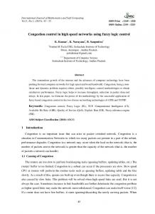
When the omega network has a fix size, and very small buffer length, but the number of LANs and time duration is increased, in this case many packets will be lost proportionally, in figure 10, we noticed the throughput is decreased because we have small buffers and many LANs with long time intervals are using the network.
433
ISBN: 972-99353-6-X © 2005 IADIS
Throughput
3000 2000 1000 0 0
10
20
30
40
No. of LANs
Figure 10. Number of LANs versus
5. CONCLUSION In the conclusion, we can classify the Omega network as open loop system. By using a suitable length buffers results in delivering all the packets, eliminate the contention on the routers, and control the congestion, which reflects a high performance in the system. In contrast using small buffers with high traffic in the network leads to full the buffers and begin losing packets, which can lead to congestion. At the same time, using huge buffer size or very huge omega network size with normal traffic, causes to increase the delay, which cause to decrease the throughput and the overall performance of the system. The network designers must choose appropriate omega network architecture, and he should compromise between the buffer size and available traffic. In this case, controlling the congestion will be satisfied and no packet losing will be occurred.
REFERENCES [1] Andrew S. Tanenbaum, “Computer Networks “, 4th edition, 2002 by Prentice Hall, [2] Vipin K., Ananth G., Anshul G., George K., “Introduction To Parallel Computing “, Benjamin /Cummings Publishing Company, 1994. [3] Joseph D. Touch. “Replication and Reduction in multistage interconnection networks”, IEEE Transaction Computers, 1999 [4] Rajeev Sivaram, Dhabaleswar K. Panda, and Craig B. Stunkel. Efficient broadcast and multicast on multistage interconnection networks using multiport encoding. IEEE Transaction on Parallel and Distributed Systems, 9(10):1004–1028, October 1998. [5] Sun Microsystems, “ Sun certified programmer for Java2 platform”, Colorado, USA, April 2000,
434