its the instantaneous rate at which a source may send pack- cth into the network 171. The marked packets, depending on their type, are then treated differently at ...
in order to ensure that it stays within reasonable limits of its allocated capacity so it will not affect other sessions in progress. Let US introduce some concepts based upon which we will propose a congestion control scheme.
control mechanism which uses knowledge of the extrinsic parameters associated with the connection and controls the source by forcing it to conform to these parameters. We refer generically to such schemes as input rate regulation schemes. The leaky bucket scheme proposed in [4] and the scheme used in PARIS [l]are examples of input rate regulation mechanisms. In [5] and [6] the authors present a particular approach to acheiving a broadband congestion control architecture, based on a “core” congestion control strategy called Bandwidth Management (BWM). The BWM core controls are applied to the cell flow of a virtual circuit(VC) and are as follows:
2.1
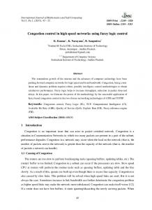
The Peaky bucket[l][4] is an end to end open-loop preventive control scheme. As shown in Fig. 1 it accepts packets from the transmitter and controls the average rate of flow in a session with a certain allowable burst rate. Tokens arrive at a fixed rate of y to the bucket. Each token serves as a permission for a certain “quota” of bytes to enter service. ,4 packet arriving at the input queue must remove an appropriate number of tokens (that depends on the packet length) before it proceeds for service. For example if a data session consists only of packets with sizes of lKbytes and 1.5Kbytes the quota size can be O X b y t e s , implying that a lKbyte packet needs 2 tokens and a 1.5Kbyte packet needs 3 tokens. If there aren’t enough tokens for the entire packet then the packet has to wait in the input queue until it collects all the tokens it needs. Packets can be of different lengths and are transmitted without fragmentation. In an ATM environment the quota can be exactly a cell. The quota system allows the leaky bucket to control the average rate at which traffic enters the network in bits/second even when packet lengths might have a large variance. Note that the bucket size is M and tokens arriving to a full bucket are dropped. The bucket capacity - M controls the maximal burst size, i.e., if many packets arrive to the queue, given that there are enough tokens in the bucket for all of them, then these packets can be transmitted back to back at the peak rate. A peak rate controller or spacer will be necessary to control the burst rate at which packets enter the network in order to avoid overwhelming a slow link on the path of a particular session.
1. For the duration of the VC, traffic entering the network is monitored in real-time and cells corresponding to
excessive traffic are then marked with a violation tag in their header indicating that these cells may be dropped at intermediate nodes in the event of congestion at nodes along the VC route.
2. Violation-tagged cells are dropped whenever they encounter a queue on their VC having more packets than a certain t lireshold. I n this paper, we describe a general scheme which may be used for rate regulation of a bursty source. Our scheme includes a marker’ [5]; which, on the average, identifies packets generated above the guaranteed rate, and a spacer which limits the instantaneous rate at which a source may send packcth into the network 171. The marked packets, depending on their type, are then treated differently at the intermediate nodes of the network. In this paper our focus will be on data traffic but such a scheme is amenable to an integrated environment. The characteristics of the analog sources can be exploited for the congestion control purpose because it is possible through suitable coding techniques to allow for partial loss of less significant information. Hierarchical sub-band coding schemes [8]allow voice and video traffic to be separated into subbands in a hierarchy of importance so that on the onset of congestion the less important sub-bands can be dropped. Section 2 will describe the general framework of the overall scheme and the methodology. Section 3 will describe in detail the generalized leaky bucket scheme proposed for packet-level congestion control. Section 4 will discuss control strategies that can be used at each intermediate node to handle congest ion.
2
Leaky Bucket and Spacer
2.2
A Marking Scheme for Optimistic Bandwidth Usage
The leaky bucket scheme with the peak rate controller results in a conservative but robust congestion preventive control scheme. In this section, we discuss an optimistic policy which makes use of the bursty nature of traffic in the network to increase the efficiency of bandwidth usage. Let us consider for now data traffic. The bursty nature of data makes it hard to estimate exactly the traffic requirements and parameters. At call set-up a negotiation between the network and the session initiator results in a reservation of a certain amount of guaranteed bandwidth or the session is blocked due to the lack of free capacity. The duration of a data session may extend over a long period (hours) but activity might exist for relatively short periods of time resulting in a gross undesutilization of the allocated network capacity. Since it is possible that most data sessions will not be active simultaneously, each active transmitter can transmit
General Framework
Congestion control can be exercised at various levels [9]. At the call level it is the decision whether to accept an incoming call or session into the network in order to avoid long term network congestion. In this paper we will discuss packet level congestion control, i.e., controlling the session’s rate ‘Note: The terms Marking and Coloring are used interchangeably
521
of packets at a node cannot exceed B. Now both green and red traffic are allowed to enter the node until the total number of packets at the node equals a threshold T after which any subsequent red arrivals to the node are blocked. Only when the total number of packets in the queue goes below the threshold T are red packets allowed into the node. Fig. 5 shows the Markov chain for this policy where the state is the total number of packets, both red and green, in the system.
that traffic at an intermediate node will come from the outputs of many leaky buckets and after having passed through other intermediate nodes. Thus as a simplifying assumption we may model the arrival process as Poisson. The buffer sizes at the nodes are finite restricting the tota: number of packets at a node to B . Using Dynamic Reversibility arguments [11][12] we can show that
where p s = A,/p: p7 = & / p i P ( m ,n ) is the Probability that there are m red and n green packets in the system.
where
The Normalized green throughput is given by
S = { m ,njm + n = B }
A,
+ A,
-; p g = -
P
A, I-1
The probablity of loss of the green for a given threshold T is given by
('4 where
pt =
(4
Now let us find a quantity of interest which is the sensitivity of the green traffic to the threshold T as we let the red traffic in(rease In the worst case let A, -+ 00.
'laking
IiInX,
r,H(T'i
-
CO
The normalized green throughput is given by
of the Normalized green throughput r
1
Once again let us see the effect of red traffic on the green as the red traffic increases. NGWlet us take limX, -+ CO of the normalized green throughput r:(T). It can be shown that
From Equation 1 it is clear that
P(m.n)
lim
AT+X
m,nES
-+
lim P ( T , B - T )
x,-m
No w
The above equation(l1) shows that for large red traffic, as expected, the green behaves as if it were arriving to a node which had only green arrivals and a finite size of B - T .
4.2
Strategy 2
4.3
Let us now examine another method which we could use to control colored traffic at a node. The scenario is the same as before, i.e., red and green packets arrive at a node at Poisson rates A, and A, respectively. The service requirement for both types is exponential with rate p. As before, Note that traffic at an intermediate node will come from the outputs of many leaky buckets and after having passed through otRer intermediate nodes. Thus as a simplifying assumption we may model the arrival process as Poisson. The total number
Ideal Case
As a means of comparison we present also a strategy which in a sense is ideal for the green traffic but would be conservative in its handling of red traffic. If the buffer is full then a green arrival will discard a red packet from the system preemptively even if the red packet is in service. This scheme will require more complex buffer management than Strategy 1 and Strategy 2 which we have previously introduced. However as a means of comparison to the other two strategies we
523
[lo] M. Sidi, W. Liu, I. Cidon, I. Gopal, " Congestion Control through Input Rate Regulation," IEEE Globecom 89.
[ 111 F. P. Kelly, Reversibility and Stochastic Networks, John
Head of Buffer
Wiley and Sons 1979. [12] K. Bala, I. Cidon, K. Sohraby, " Congestion Control for High Speed Packet Switched Networks," Center for Telecommunications Research at Columbia University Technical Report No: CU/CTR/TR-l73-90-10. j
Buckei S m=M
SO
i Token Generat-r Rate
cnough
y
F q 1 The ample Le&
Bucker Scheme
Xr FIG 4 Iniermediatc Ncdc
FIG 2 Lcair) B x k c i . Marker and Spacer
525
RG
5: Markov chmn for Suatcgy ;
-"L
-14
0
10
SO
20
4P
T
FIG
8
526
50
6C