*1 Set in the [Serial Port] menu of the ladder software RSLogix5000 by Rockwell.
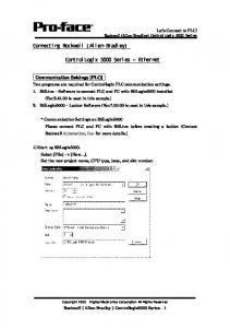
... Two programs are required for Controllogix PLC communication settings. 1.
4 MicroLogix™ 1000 Programmable Controllers. Publication 1761-IN001C-EN-P
- March 2008. Important User Information. Because of the variety of uses for the ...
Micro800 PLC family, together with the Connected Components ... download and
debugging to controller ... Program download via USB programming port.
Below is a list of available input and output sets available for the MicroLogix.
1100 PLC we have in the lab. The MicroLogix 1100 is capable of handling four I/
O ...
PLC Connection Guide. 1. PLC Connection .... FATEK FB Series . ...... Note: The
formats of TM, TD, TF and TI in PLC software are represented as TXA[B]. “X”.
Mar 17, 2014 ... PLC Connection Guide. 1 ... Beckhoff TwinCAT PLC (Ethernet) – Free Tag.
Names . .... EMERSON PLC EC20 . ... FATEK FB/FBs/B1/B1z Series . ...... For
example: Model PO3242, range of “A” is ”0” and range of “B” is 0 ~ 7.
Two new MicroLogix 1000 chapters: MicroLogix Communication Instruction.
MicroLogix Communication Protocols. Ch. 9. Ch. 14. Revised information on how
to ...
downloaded to the PLC when ready for the final test and debug. In addition, there
is usually only one project (program) for each PLC on the network. For these ...
Connecting Rockwell (Allen-Bradley). ControlLogix 5000 Series ‒ Ethernet.
Communication Settings [PLC]. Two programs are required for Controllogix PLC
...
poll other Allen-Bradley PLC such as MicroLogix, SLC5, and PLC5E. 1 ... The
Digi One IAP allows access to the ControlLogix concurrently by Modbus
protocols ...
Results 9 - 16 - 17-4. Chapter 18. Using Processor Input Interrupts. Using This Chapter . ...... Use 6.35 mm (0.25 inch) mounting bolts to attach the I/O chassis to the enclosure ...... Connects PCMCIA Bus notebook computers to DH+. 1784-PCM5.
thickness of the test piece are complied with, there will be no danger of indenting ...... (1) Measuring by means of an elastic proving device previ- ously calibrated ...
The Delta 24 inch Scroll Saw is designed for use in ... primarily designed for
scroll saw work on stock less .... SITE-r lfigr' 3l-OW 53 I i 65 60 Glut—nu“ .... to
repair or replat'e any port or parts of Rockwell Power Tools or Rockwell Power
Tool.
The MicroLogix family of controllers provides five levels of control. Small on size,
big on performance, the MicroLogix 1000 controller offers control capabilities in ...
Rockwell Hardness Sensitivity Coefficients HR15N. ISO 6508-1 defines the
Rockwell superficial hardness value, HRN, as: h. HRN. -. =100 where:.
May 23, 1980 - Efforts were also made to prepare NF salts containing the following anions, NO39 ClF 40. RrF4O, IF. , BrO4', and IO4 (Appendix G), and MF.
Communication Settings for. Allen Bradley (Micrologix 1000) and. IDEC
Touchscreens. (5.7” HG2F, 10.4” HG3F and 12.1” HG4F) ...
PanelView™ Plus 6 HMI terminals are used for applications with a need to
monitor, control, and display ... View Studio for Machine Edition (ME) software
and have FactoryTalk View ME Station .... PDF reader ..... Use 1761-NET-ENI
module.
Catalog Numbers 1786-TPR, 1786-TPS, 1786-TPYR, 1786-TPYS .... The
ControlNet taps do not require the use of DIN rails made of specific materials.
However ...
Quality Manual (similar to the internal procedure 900-20-02 Quality ... Many sites
within RA are ISO 9001 certified but the Quality Management System requires ...
IEC 60077-1, -2; NF F 62-000; Requirements for railway applications. Approvals
... IEC 61373 (shock railways): category 1, class B, 5 G (30 ms). Shock half sinus
...
Nov 22, 2015 - specifically the convergence of information technology (IT) and operations ... early career workers â i
Sep 4, 2011 - Using gaming software and computer-aided design .... All Nippon Airways (ANA) ..... the software on new ha
Rockwell (Allen-Bradley) MicroLogix1200/1500 Series. Connecting ... Two
programs are required for MicroLogix PLC communication settings. 1. RSLinx ...
Let’s Connect to PLC! Rockwell (Allen-Bradley) MicroLogix1200/1500 Series
Connecting Rockwell (Allen-Bradley) PLC MicroLogix 1200/1500 Series ‒Serial Communication Setting Sample MicroLogix 1200/1500 Series GP Settings
PLC Settings
Speed
19200bps
Baud Rate
19200bps
Data Length
8bits
−
−
Stop Bit
1bit
−
−
Parity
Even
Parity
Even
Flow Control
ER (DTR/CTS)
−
−
SIO Type
RS-232C
−
−
0 to 254
Node
SIO Type
RS-232C
−
−
−
−
Driver
DF1
DH Address GP DH Address
Address
0 to 254
PLC*1 Half
Duplex
Slave −
−
Control Line
No Handshaking
−
−
Error Detection
BCC
−
−
EOT Suppression
Not Checked
−
−
Duplicate Packed Not Checked Detect
−
−
Poll Timeout
3000
−
−
Message Retries
3
−
−
Pre Transmit
0
Delay
*1 Set with same address for [DH Address GP] and [DH Address PLC]
Copyright 2003
Digital Electronics Corporation All Rights Reserved
Rockwell(Allen-Bradley) MicroLogix1200/1500 Series Serial−1
Let’s Connect to PLC! Rockwell (Allen-Bradley) MicroLogix1200/1500 Series
Communication Settings [PLC] Two programs are required for MicroLogix PLC communication settings. 1.
RSLinx – Software to connect PLC and PC with RSLogix500 installed (Ver.2.41.00 is used in this sample.)
2.
RSLogix500 – Ladder Software (Ver.5.20.00 is used in this sample.) * Communication Settings on RSLogix500 Please connect PLC and PC with RSLinx before creating a ladder. (Contact Rockwell Automation, Inc. for more details.)
1) Start up RSLogix500. 2) Select the CPU type
Communication Settings can be left by default.
Copyright 2003
Digital Electronics Corporation All Rights Reserved
Rockwell(Allen-Bradley) MicroLogix1200/1500 Series Serial−2
Let’s Connect to PLC! Rockwell (Allen-Bradley) MicroLogix1200/1500 Series
3) Click[Channel Configuration].
4) A dialog box will appear. Then double-click the [Channel 0] tab and set the channel.
Copyright 2003
Digital Electronics Corporation All Rights Reserved
Rockwell(Allen-Bradley) MicroLogix1200/1500 Series Serial−3
Let’s Connect to PLC! Rockwell (Allen-Bradley) MicroLogix1200/1500 Series
System cannot be operated with other settings. System cannot be operated with other settings. System cannot be operated with other settings.
BCC
Station Address
0 to 255
Set with the same address as DH GP Address of GP.
* Other settings can be left by default.
⑤
Click the [OK] button after complete the settings.
⑥
Download the driver settings. Click [OFFLINE] and select [Download…].
Copyright 2003
Digital Electronics Corporation All Rights Reserved
Rockwell(Allen-Bradley) MicroLogix1200/1500 Series Serial−4
Let’s Connect to PLC! Rockwell (Allen-Bradley) MicroLogix1200/1500 Series
⑦ The dialog box as below will be displayed, and then click the [OK] button.
⑧ The following alert dialog box will appear, and then click [Yes].
⑨ The below dialog box warning “Loss of communication on CURRENT channel (CH0) will occur.” will be displayed, and then click [Apply].
The port settings for MicroLogix 1200/1500 are completed.
Copyright 2003
Digital Electronics Corporation All Rights Reserved
Rockwell(Allen-Bradley) MicroLogix1200/1500 Series Serial−5
Let’s Connect to PLC! Rockwell (Allen-Bradley) MicroLogix1200/1500 Series
Note) When redownloading a project, please be noted that you may not be able to download it because 0 Channel of PLC has been changed to the port settings to communicate to GP. In case to redownload it, open the cover on MicroLogix 1200/1500 and press the communication toggle push button. After pressing the button, the communication settings of the RS-232C port on the Base Unit will be the default settings. Confirm that PLC is recognized on RSLINX before redownloading.
Default Communication Settings of RS-232C Port on Base Unit Setting Item Protocol Baud Rate Parity Stop Bits Node Address Control Line Error Detection Embedded Responses Duplicate Packet Detect ACK Timeout NAK Retries ENQ Retries
Copyright 2003
Setting Detail DF1 Full-Duplex 19,200 bps none 1bit 1 No Hand shaking CRC auto detect enable 50 Counts 3 retries 3 retries
Digital Electronics Corporation All Rights Reserved
Rockwell(Allen-Bradley) MicroLogix1200/1500 Series Serial−6
Let’s Connect to PLC! Rockwell (Allen-Bradley) MicroLogix1200/1500 Series
Assigning Devices With Rockwell PLC, the required arrays and number of elements are assigned on RSLogix500. If you connect it to GP/GLC without assigning here, a host communication error will occur. Array Name
No. of Elements
[File Type]
The project file has array types and array numbers as left.
Copyright 2003
Digital Electronics Corporation All Rights Reserved
Rockwell(Allen-Bradley) MicroLogix1200/1500 Series Serial−7
Let’s Connect to PLC! Rockwell (Allen-Bradley) MicroLogix1200/1500 Series
Only one element exists by default. Because N array to which the system start address is assigned needs 20 elements, it is necessary
to
increase
elements.
To increase these elements, start setting as left.
Enter
the
number
of
required
elements. * N7 needs at least 20 elements to allocate the system start address.
Copyright 2003
Digital Electronics Corporation All Rights Reserved
Rockwell(Allen-Bradley) MicroLogix1200/1500 Series Serial−8
Let’s Connect to PLC! Rockwell (Allen-Bradley) MicroLogix1200/1500 Series
As you can see left, 255 elements have been created in N7.
[Creating New Array] It is possible to create multiple arrays with Rockwell PLC.
Array No.=15
Array Type=N
Array No.=10
Array Type=N
Array No.=7
Array Type=N
e.g.)
To start creating new arrays, follow as left.
Copyright 2003
Digital Electronics Corporation All Rights Reserved
Rockwell(Allen-Bradley) MicroLogix1200/1500 Series Serial−9
Let’s Connect to PLC! Rockwell (Allen-Bradley) MicroLogix1200/1500 Series
Specify the array number.
Select the array type.
Enter the number of the required elements.
N9 has been newly created with 255 elements.
Following this way, create arrays and elements towards each array type. Duplication of array numbers following array type is not allowed. For example, you cannot create such as N15, B15.
Copyright 2003
Digital Electronics Corporation All Rights Reserved
Rockwell(Allen-Bradley) MicroLogix1200/1500 Series Serial−10


![Enhanced and Ethernet PLC-5 Programmable Controllers - Rockwell ... [PDF]](https://m.moam.info/img/260x300/enhanced-and-ethernet-plc-5-programmable-controlle_647d2107098a9ede188b4579.jpg)