Connecting Wireless Sensor Networks to the Internet – a 6lowpan Implementation for TinyOS 2.0 Master’s Thesis Mat´ uˇs Harvan
[email protected] May 2007
Thesis Supervisor:
J¨ urgen Sch¨onw¨alder
Review Committee:
J¨ urgen Sch¨onw¨alder Andreas Birk
Jacobs University Bremen School of Engineering and Science Campus Ring 1 28759 Bremen Germany
I hereby certify that this thesis is independent work that has not been submitted elsewhere.
Abstract A 6lowpan implementation for the TinyOS 2.0 embedded operating system has been developed. It supports the 6lowpan adaptation layer with handling of the Fragmentation, Mesh Addressing and Broadcast headers. The 6lowpan-specified HC1 compression of the IPv6 header and the HC UDP compression of the UDP header are supported as well as handling of the uncompressed headers. Although not all requirements for a full IPv6 stack are implemented, the implementation can respond to ICMP echo requests and handles communication over the UDP protocol. It has been tested on the TelosB and MicaZ hardware platforms.
Acknowledgments I would like to thank my supervisor Prof. J¨ urgen Sch¨onw¨alder for supervising this thesis, for his support during my work and for many helpful comments.
Contents 1 Introduction
1
2 Hardware 2.1 Hardware platforms . . . . . . . . . . . . . . . . . . . . 2.2 PHY and MAC layer – 802.15.4 . . . . . . . . . . . . . 2.2.1 Network topologies . . . . . . . . . . . . . . . . . 2.2.2 Data transfers in beacon-enabled and non-beacon 2.2.3 Robustness . . . . . . . . . . . . . . . . . . . . . 2.2.4 Security . . . . . . . . . . . . . . . . . . . . . . . 2.2.5 Implications for higher layers . . . . . . . . . . . 2.2.6 802.15.4a Task Group . . . . . . . . . . . . . . . 2.2.7 802.15.4b Task Group . . . . . . . . . . . . . . . 2.2.8 ZigBee Alliance . . . . . . . . . . . . . . . . . . . 2.3 The TinyOS operation system . . . . . . . . . . . . . . . 2.3.1 NesC . . . . . . . . . . . . . . . . . . . . . . . . . 2.3.2 Networking in TinyOS . . . . . . . . . . . . . . .
2 . . . . . 2 . . . . . 3 . . . . . 4 networks 5 . . . . . 6 . . . . . 7 . . . . . 7 . . . . . 8 . . . . . 8 . . . . . 8 . . . . . 8 . . . . . 9 . . . . . 10
3 Above the link-layer 3.1 Internet Protocol Version 6 . . 3.1.1 Header format . . . . . 3.1.2 Addressing architecture 3.1.3 Upper-layer checksums . 3.1.4 ICMPv6 . . . . . . . . . 3.1.5 Neighbor discovery . . . 3.2 UDP . . . . . . . . . . . . . . . 3.3 6lowpan . . . . . . . . . . . . . 3.3.1 Addressing modes . . . 3.3.2 Adaptation layer . . . . 3.3.3 Header compression . . 3.3.4 Provisions for meshes .
. . . . . . . . . . . .
. . . . . . . . . . . .
. . . . . . . . . . . .
. . . . . . . . . . . .
. . . . . . . . . . . .
. . . . . . . . . . . .
. . . . . . . . . . . .
. . . . . . . . . . . .
. . . . . . . . . . . .
. . . . . . . . . . . .
. . . . . . . . . . . .
. . . . . . . . . . . .
. . . . . . . . . . . .
. . . . . . . . . . . .
. . . . . . . . . . . .
. . . . . . . . . . . .
. . . . . . . . . . . .
. . . . . . . . . . . .
. . . . . . . . . . . .
12 12 12 13 15 15 16 18 19 19 20 24 26
4 Implementation 4.1 Design overview . . . . . . . . . 4.1.1 Design principles . . . . 4.1.2 Modules and interfaces . 4.1.3 Receiving a packet . . . 4.1.4 Sending a packet . . . . 4.1.5 Buffers . . . . . . . . . .
. . . . . .
. . . . . .
. . . . . .
. . . . . .
. . . . . .
. . . . . .
. . . . . .
. . . . . .
. . . . . .
. . . . . .
. . . . . .
. . . . . .
. . . . . .
. . . . . .
. . . . . .
. . . . . .
. . . . . .
. . . . . .
. . . . . .
28 28 28 29 30 31 33
2
. . . . . . .
. . . . . . .
. . . . . . .
. . . . . . .
. . . . . . .
. . . . . . .
. . . . . . .
. . . . . . .
. . . . . . .
36 37 37 37 38 40 41
5 Related work 5.1 IP stack implementations for WSNs . . . . . . . . 5.1.1 6lowpan implementations . . . . . . . . . . 5.1.2 uIP . . . . . . . . . . . . . . . . . . . . . . 5.1.3 Proxy . . . . . . . . . . . . . . . . . . . . . 5.2 Operating systems and platforms . . . . . . . . . . 5.2.1 Contiki . . . . . . . . . . . . . . . . . . . . 5.2.2 RoboCube and CubeOS . . . . . . . . . . . 5.2.3 Unix-like systems . . . . . . . . . . . . . . . 5.3 Alternative link-layer standards . . . . . . . . . . . 5.4 Mesh networking – 802.15.5 . . . . . . . . . . . . . 5.5 TCP/IP optimizations for wireless sensor networks 5.6 DTN . . . . . . . . . . . . . . . . . . . . . . . . . . 5.6.1 Endpoint identifiers (EID) . . . . . . . . . . 5.6.2 Priority classes . . . . . . . . . . . . . . . . 5.6.3 Delivery options . . . . . . . . . . . . . . . 5.6.4 Custody transfers . . . . . . . . . . . . . . . 5.6.5 Contact types . . . . . . . . . . . . . . . . . 5.6.6 Fragmentation . . . . . . . . . . . . . . . . 5.6.7 Time synchronization . . . . . . . . . . . . 5.6.8 Security . . . . . . . . . . . . . . . . . . . . 5.6.9 State maintenance . . . . . . . . . . . . . . 5.6.10 Convergence layer . . . . . . . . . . . . . . 5.6.11 LTP . . . . . . . . . . . . . . . . . . . . . .
. . . . . . . . . . . . . . . . . . . . . . .
. . . . . . . . . . . . . . . . . . . . . . .
. . . . . . . . . . . . . . . . . . . . . . .
. . . . . . . . . . . . . . . . . . . . . . .
. . . . . . . . . . . . . . . . . . . . . . .
. . . . . . . . . . . . . . . . . . . . . . .
. . . . . . . . . . . . . . . . . . . . . . .
. . . . . . . . . . . . . . . . . . . . . . .
44 44 44 44 45 47 47 47 48 48 49 50 53 54 54 54 55 55 56 56 57 57 58 58
4.2 4.3 4.4
4.1.6 Fragment reassembly . 4.1.7 Addresses . . . . . . . 4.1.8 Link-layer . . . . . . . 4.1.9 Encountered problems 6lowpan for Linux . . . . . . Testing . . . . . . . . . . . . Evaluation . . . . . . . . . . .
. . . . . . .
. . . . . . .
. . . . . . .
. . . . . . .
. . . . . . .
. . . . . . .
. . . . . . .
. . . . . . .
. . . . . . .
. . . . . . .
. . . . . . .
6 Conclusions
60
Bibliography
61
Chapter 1
Introduction Wireless sensor networks consist of numerous tiny nodes equipped with various sensors and a radio interface for communication. Among the applications are environment monitoring such as forest fire detection and water or air quality monitoring, wildlife monitoring, smart spaces, medical systems and robotic exploration. Due to the nature of the application, access to the motes may not be feasible after initial deployment. Hence, the devices have to run for extended periods of time on battery power, resulting in low-power, energy-saving designs. Traditionally, the wireless sensor networks have used custom, light-weight network protocols such as Active Messages. However, given that the motes are now commonly equipped with an 802.15.4 radio interface and the 6lowpan adaptation layer allows the exchange of IPv6 packets over 802.15.4 links, enabling IPv6 connectivity on wireless sensor networks and connecting them to the global Internet becomes feasible. By being able to natively support the IPv6 protocol, these devices would become first-class network citizens capable of communication over the Internet with any other IPv6-enabled host, benefit from the standardized and already estabilished technology as well as from the plethora of readily available applications. To this end a 6lowpan/IPv6 stack has been implemented for TinyOS 2.0, an embedded operating system commonly used in wireless sensor networks. The implementation includes the 6lowpan adaptation layer with fragmentation and fragment reassembly, handling of the Mesh Addressing and Broadcast headers, HC1 compression of the IPv6 header and HC UDP compression of the UDP header. Handling of the uncompressed headers is supported as well. While the full ICMPv6 protocol is not supported, the ICMP echo mechanism and support for the UDP protocol have been implemented. The implementation has been tested on the MicaZ and TelosB motes from CrossBow Technologies. The hardware platforms used in this project, the TelosB and MicaZ motes, the 802.15.4 wireless communication standard and the TinyOS 2.0 operating system are introduced in more detail in Chapter 2. The IPv6 and UDP protocols and the 6lowpan adaptation layer are described in Chapter 3. The implementation is discussed and evaluated in Chapter 4. Chapter 5 gives an overview of related work, other 6lowpan or IP stack implementations, alternative hardware platforms, operating systems and link layers for wireless sensor network scenarios, the 802.15.5 mesh extensions and the Delay Tolerant Networking approach. The work is summarized in Chapter 6 and possible further work is discussed. 1
Chapter 2
Hardware The hardware platforms used in the project, the TelosB and MicaZ motes, are described in Section 2.1. 802.15.4, the link-layer standard of the radio interface on the motes, is discussed in Section 2.2 and the operating system used on the motes, TinyOS 2.0, is introduced in Section 2.3, including a discussion of its networking capabilities, the 802.15.4 implementation and its compliance with the 802.15.4 standard.
2.1
Hardware platforms
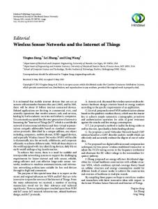
The hardware platforms chosen for this project are the TelosB and MicaZ motes. Both platforms were originally developed at UC Berkeley and are now produced by the Crossbow Technology company. Both platforms are tiny, low-power motes with restricted resources, equipped with an 802.15.4 RF interface. The TelosB motes feature a Texas Instruments MSP430 MCU. It is a 16bit RISC MCU clocked at 8 MHz and has 16 registers. The platform offers 10 kB of RAM, 48 kB of flash memory and 16 kB of EEPROM. Requiring at least 1.8 V, it draws 1.8 mA in the active mode and 5.1 µA in the sleep mode. The MCU has an internal voltage reference and a temperature sensor. Further sensors available on the platform are a visible light sensor (Hamamatsu S1087), a visible to IR light sensor (Hamamatsu S1087-01) and a combined humidity and temperature sensor (Sensirion SHT11). The MicaZ motes feature an Atmel AVR Atmega128L MCU. It is an 8-bit
Figure 2.1: TelosB mote [12]
2
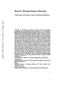
Figure 2.2: MicaZ mote [11] and the MTS 310 sensorboard [13] RISC MCU with 32 registers. The platform offers 4 kB of RAM, 128 kB of flash memory and 4 kB of EEPROM. Requiring at least 2.5 V, it draws 8 mA in the active mode and 15 µA in the sleep mode. The mote is similar to the Mica2 mote, the main difference being a different radio interface. The MCU has an internal voltage reference. The voltage reference is useful for monitoring the battery voltage. Otherwise the MicaZ mote alone does not contain any sensors. However, using the 51-pin Mica2 connector, various sensor boards can be connected. For this project, the MTS 300 sensor board has been available. It contains light, temperature and acoustic (a microphone) sensors as well as a speaker. Other sensor boards with various sensors, such as accelerometers or magnetometers are also available. The radio chipset used on both platforms is the Chipcon CC2420. It provides a 128-byte TX/RX buffer and AES encryption. While the TelosB mote has a USB connector and can directly be plugged into a PC for communication or reprogramming, the MicaZ platform needs to be attached to a programming board via the 51-pin connector. In this project, the MIB 520 programming board with a USB interface to the PC has been used. Clearly, these motes are suitable for low data rate applications requiring only minimum data processing. Spending most of their time in the sleep mode, the motes can run for several years on 2 AAA batteries. However, target costs of less than 10 cents per mote would enable networks with potentially thousands of devices. A broader overview of other available embedded hardware platforms can be found in Section 5.2.
2.2
PHY and MAC layer – 802.15.4
The 802.15.4 standard was developed by the 802.15.4 Task Group within the IEEE and defines the physical layer (PHY) and medium access control (MAC) layer specifications for low data rate wireless personal area networks (LR WPANS). Such networks are typically limited to a personal operating space (POS) of up to 10 meters and involve little or no infrastructure. The standard provides for low complexity, low power consumption, low data rate wireless connectivity among a wide range of inexpensive devices. Among others, wireless sensor networks seem to be a suitable application scenario for 802.15.4 networks.
3
2.2.1
Network topologies
An 802.15.4 network consists of two types of devices, full-function devices (FFD) and reduced-function devices (RFD). An FFD can operate as a personal area network (PAN) coordinator, a coordinator or a device while an RFD can only act as a device. An FFD can talk to RFDs and other FFDs, while an RFD can only talk to FFDs. An RFD is intended for very simple applications, such as a light switch or a passive sensor, with no need to send large amounts of data. An RFD may associate with only one FFD at a time. As a result of these restrictions, an RFD needs only minimal resources and memory capacity. An 802.15.4 network is constituted of at least two devices within a POS communicating on the same physical channel. It shall contain at least one FFD acting as the PAN coordinator. The network may operate in a star or a peerto-peer topology. In the star topology devices communicate with a single central PAN coordinator. While RFDs act as communication end-points only, a PAN coordinator mainly routes communication around the network. Different star networks operate independently of each other. This is achieved by using a PAN identifier which is unique within the radio range. After the PAN coordinator has chosen a PAN identifier, it can allow other devices, both FFDs and RFDs, to join the network. The peer-to-peer topology also has a PAN coordinator, but additionally devices can communicate directly with each other. This allows for more complex topologies, such as a mesh topology or a cluster-tree. The cluster-tree network is a special case of a peer-to-peer network with mostly FFD devices. As a RFD can associate to only one FFD, RFDs can participate in cluster-tree networks only as leave nodes. Any of the FFDs can act as coordinators and provide synchronization services to other devices and coordinators. One of these coordinators becomes the overall PAN coordinator. The PAN coordinator forms the first cluster by picking an unused PAN identifier, becoming the cluster head (CLH) with cluster identifier (CID) of zero and broadcasting beacon frames. Devices receiving these beacon frames may request joining the cluster at the CLH. If the PAN coordinator grants the joining, the new device will be added to the PAN coordinator’s neighbor list and start broadcasting beacons as well. Other devices may then join the network at this new device as well. If it is not possible to join the network at the CLH, a device searches for another parent device. The PAN coordinator may instruct another device to become the CLH of a new adjacent cluster. This could happen if predetermined application or network requirements are fulfilled. As other devices connect, a multicluster network structure is formed. In its simplest form, the cluster tree network consist of only a single cluster, but larger networks may be formed as a mesh of multiple neighboring clusters. This is illustrated in Figure 2.3. The multicluster structure trades increased message latency for an increase in coverage area. Such a peer-to-peer network can clearly be ad-hoc, self-organizing and self-healing. The 802.15.4 standard provisions for two types of addresses. All devices shall have unique 64-bit extended IEEE addresses. These extended address can be used for direct communication within the PAN. Additionally, devices can be allocated 16-bit short addresses by the PAN coordinator during association with the PAN coordinator.
4
Figure 2.3: Cluster Tree Network – lines represent parent-child relationships rather than communication flow. Image taken from [25]. frequency 2400 – 2483.5 MHz 902 – 928 MHz 868 – 868.6 MHz
data rate 250 kbps 40 kbps 20 kbps
Table 2.1: 802.15.4 frequency bands 3 frequency bands using different data rates are available for 802.15.4. They are summarized in Table 2.1.
2.2.2
Data transfers in beacon-enabled and non-beacon networks
There are two modes of operation of an 802.15.4 network, a beacon-enabled and a non-beacon mode. In the beacon-enabled mode, an optional superframe structure is used. It is defined and bounded by the beacons broadcasted by the coordinator. The beacons are used to synchronize devices, identify the PAN and describe the superframe structure. The superframe is divided into 16 equally sized slots. A beacon is broadcasted in the first slot of each superframe. An illustration is available in Figure 2.4. Devices wishing to communicate during the contention access period (CAP) between two beacons compete with other devices using s slotted CSMA-CA (Carrier Sense Multiple Access - Collision Avoidance) mechanism. The superframe may be divided into an active and an inactive portion. During the inactive portion the coordinator does not interact with the PAN and may enter a low-power mode. The coordinator may dedicate portions of the active superframe to guaranteed time slots (GTSs) for low-latency appli5
Figure 2.4: Superframe structure. The Contention Free Period is optional. Image taken from [25]. cations or bandwidth guarantees. The GTSs form the contention-free period (CFP) and appear at the end of a superframe. There may be at most 7 GTSs per superframe and a GTS may occupy more than one time slot. There is a difference between data transfers from a device to a coordinator and vice-versa. For data transfers from a device to a coordinator, the device uses slotted CSMA-CS to transmit its data frame. For data transfers from a coordinator to a device, the coordinator indicates in the beacon that data is pending for the device. The device periodically listens for the beacon broadcasts. If a data transfer is pending for it, it transmits a MAC command requesting the data transfer. This MAC command is transmitted using slotted CSMA-CA. Upon reception of the MAC command, the coordinator uses slotted CSMA-CA to transmit the data frame to the device. The coordinator may decide that non-beacon mode is used. Then there is no superframe structure and devices use unslotted CSMA-CA instead of slotted CSMA-CA. Note that beacons are still needed for network association. For data transfer from a coordinator to a device, the device has to request the data transfer using a MAC command. If there is data pending for the device, it is transmitted in a data frame. Otherwise, a data frame with zero-length payload is transmitted, indicating no pending data for the device. For peer-to-peer data transfers the devices either receive constantly or synchronize with each other. In the former case unslotted CSMA-CA is used while the latter case is beyond the scope of the 802.15.4 standard. The 802.15.4 protocol has been designed to favor battery-powered devices. These can spend most of their time in a sleep state saving battery power. However, they have to periodically wake up and check if there are any messages pending by listening to beacons. This allows the application designer to balance between battery consumption and message latency.
2.2.3
Robustness
Robustness in the 802.15.4 networks is achieved by using optional frame acknowledgments, CSMA-CA mechanisms and data verification. The 802.15.4 standard accommodates optional frame acknowledgments for MAC command frames and data frames. Note that in both non-beacon and beacon-enabled networks, these acknowledgments are sent directly without using CSMA-CA. The non-beacon networks use an unslotted CSMA-CA channel access mechanism. When a device wishes to transmit a frame, it has to wait for a random period of time. If the channel is idle after this random period of time, data shall
6
be transmitted. In case the channel is busy, the device shall wait for another random period of time before retrying. Beacon-enabled networks use a slotted CSMA-CA channel access mechanism. The backoff slots are aligned with the start of the beacon transmission. A device wishing to transmit during the CAP period waits for a random number of backoff slots. If the channel is idle afterwards, it can transmit. Otherwise, it waits for another random number of backoff slots before retrying. For the data verification part, a 16-bit cyclic redundancy check (CRC) is used on every frame to detect bit errors.
2.2.4
Security
Several security services such as maintaining an access control list (ACL) and using symmetric-key cryptography to protect transmitted frames are specified by the standard. Using these services, devices may operate in one of the three security modes: unsecured, ACL and secured mode. In the unsecured mode, no security services are used. Devices operating in the ACL mode maintain ACL lists of devices from which they are willing to receive frames. Devices operating in the secured mode use cryptography services in addition to ACLs. The cryptography services include data encryption for beacon, command and data payloads, usage of a message integrity code to provide frame integrity, i.e. to protect data from being modified by parties not sharing the encryption key, and sequential freshness using an ordered sequence of inputs to reject replayed frames. The freshness checking works by comparing the freshness value of a received frame with the last known freshness value. If it is newer, the check has passed and the last known freshness value is updated. The distribution of the symmetric encryption keys is not specified by the 802.15.4 standard.
2.2.5
Implications for higher layers
From the viewpoint of higher network layers, an important aspect of 802.15.4 is its limitation on the frame size. The PHY header uses a 7 bit field to specify payload length in bytes (0-127 bytes). Taking into account the PHY and MAC layer headers, this leaves a Maximum Data Length of 102 bytes for the higher layers. Further interesting implications on the IP traffic are mentioned in [40]: 1. Links are predominantly bimodal for short packet bursts. 2. Sporadic traffic observes intermediate links, which are due to SNR variations. 3. There are ETX asymmetries, which are larger over longer time intervals. 4. Acknowledgement failures are correlated. The 802.15.4 protocol is defined in the 802.15.4-2003 standard. This document was approved in May 2003 and published in October 2003. With releasing of the standard, the work of the 802.15.4 task group has been completed, the group was hibernated and two new task groups, 802.15.4a and 802.15.4b, have been formed.
7
2.2.6
802.15.4a Task Group
The 802.15.4a Task Group is developing an amendment to the current 802.15.42003 standard for an alternate PHY to provide high precision ranging and location capability with 1 meter accuracy and better, high aggregate throughput, ultra low power, higher data rates, longer range, lower power consumption and lower cost. The baseline specification has been selected in March 2005 to include two optional PHYs consisting of a UWB Impulse Radio operating in the unlicensed UWB spectrum and a Chirp Spread Spectrum operating in the unlicensed 2.4GHz spectrum. The UWB Impulse Radio should be able to deliver high precision ranging. The final standard is expected to be published by IEEE in March 2007.
2.2.7
802.15.4b Task Group
The 802.15.4b Task Group is refining the current 802.15.4-2003 specification to clear up ambiguities and resolve inconsistencies. Furthermore, the group is supposed to make specific extensions such as a faster sub-GHz physical interface, add support for time synchronization, reduce unnecessary complexity, increase flexibility in security key usage and consider newly available frequency allocations. The IEEE 802.15.4b standard has been approved in June 2006 and is waiting for publication.
2.2.8
ZigBee Alliance
While the IEEE 802.15.4 standard provides the lower network layers, the ZigBee alliance [42] is supposed to provide the upper layers ranging from the network layer to the application layer, including application profiles. The alliance provides interoperability compliance testing and marketing of the standard. It intends to ensure cross-vendor compatibility, i.e. it should guarantee that a light switch from one company works with the lights from another company. The ZigBee standard has been publicly released in June 2005. In December 2005 there have been 6 compliant platforms. These upper layers provided by Zigbee usually are application-specific and do not use a general purpose protocol such the Internet Protocol.
2.3
The TinyOS operation system
TinyOS [20] is an event-driven embedded operating system. It was designed for extremely restricted devices such as the wireless sensor network motes. It has a very small footprint, with the core OS requiring only 400 bytes of code and data memory. The system provides a set of reusable components which can be combined together. The components implement hardware abstractions, access to various sensors and actuators via a higher level interface, a scheduler handling tasks and hardware interrupts, a timer interface, access to storage by using the flash memory on the motes, access to the radio and networking support via Active Messages. Active Messages are described in Section 2.3.2. All memory is allocated statically and there is no dynamic memory allocation, no memory mamangement and no virtual memory. There also is no kernel space and user space differentiation and no process management. There are no 8
uses Component
Interface provides consists of Command
Event
Figure 2.5: NesC components and interfaces blocking operations. All long-latency operations are split-phase, i.e. commands requesting an operation return immediately and completion of the operation is signaled with an event. TinyOS originated at UC Berkeley and is now developed by a consortium lead by UC Berkeley. Currently there are two versions, 1.1 and 2.0. The newer 2.0 version is not backwards compatible with the 1.1 version. In this project, the 2.0 version has been used.
2.3.1
NesC
The TinyOS operating system is written in the nesC language [20]. NesC is a dialect of the C language. It is a “static” language with no dynamic memory allocation and no dynamic linking. This allows for whole program analysis at compile time, resulting in efficient optimizations. Furthermore, safety checks such as data-race detection are also performed at compile time. The nesC compiler works as a pre-processor producing a C program as output. This C program is then compiled using a gcc compiler for the specific platform such as msp430-gcc or avr-gcc. NesC applications are based on interfaces and components. A component provides and uses interfaces. An interface is a set of commands and events. In case a component provides an interface, then commands are functions provided by this component and can be executed by other components. Events can be signaled by other components and have to handled by this component by providing a handler function. Having both commands and events allows for bidirectional communication between the components. A nesC application consists of components. The components are connected together by the application using a wiring specification, which is independent of the component implementations. A component using an interface is wired to another component providing that interface. This allows to break down the implementation into different components and then flexibly combine them together in order to create an application. Components are of two types, configurations and modules. A module implements interfaces. A configuration connects modules together via their interfaces by providing a wiring specification. A nesC application is then a top-level configuration. An illustration of the relations between components and interfaces is in Figure 2.5. The notion of components, interfaces and wiring allows for a component-based architecture of the TinyOS system. Concurrency in nesC and TinyOS is achieved by using tasks. A task is
9
defined as a void function (without a return value) with the task keyword. By using the post operation a task can be placed on the internal task queue of TinyOS, which is processed in FIFO order. The TinyOS scheduler later schedules the task to run. Once this happens, the task runs to completion before another task is run. In other words, tasks do not preempt each other. However, it is possible for a task to be preempted by a hardware event. Another concurrency-related feature of nesC is the division of code into synchronous and asynchronous. By default, code is synchronous unless marked as asynchronous. The important difference is that asynchronous code can only call asynchronous code but not synchronous code. A low-level hardware event handler would then be asynchronous. To get to synchronous code it would post a task. The task could then contain synchronous code. The tasks and the synchronousasynchronous code distinction allow TinyOS to support concurrency with low overhead. Although all memory is allocated statically, the PoolC component offers a dynamic memory-like pool. Internally, the component contains a statically allocated array with instances. These are all of the same type. By using the get operation, an instance can be requested from the pool. The put command allows to return it back into the pool. The size of the pool, i.e. the size of the internal array, is not runtime changeable as the array is allocated statically.
2.3.2
Networking in TinyOS
TinyOS networking is based on Active Messages [21]. Active Messages are sent as 802.15.4 frames and the Active Message addresses are used as link-layer addresses, the 802.15.4 short addresses. The Active Message addresses are 16 bits long and each mote has one such address. The all ones 0xFFFF address is a broadcast address and frames destined to it are received by every mote. The Active Message header is defined to match the header of an 802.15.4 data frame. However, the Active Message header contains an additional 1-octet long dispatch field before the Active Message payload. This dispatch field is then the first octet in the 802.15.4 payload. It is used to multiplex received messages between different applications on the same mote. Active Messages are represented in TinyOS as a message t structure. For platforms with an 802.15.4 radio it contains a buffer for the complete 802.15.4 frame, including the header and the payload, as well as some additional information such as the transmission power or the rssi and lqi values for a given frame. Active messages are sent using a split-phase interface, AMSend. Sending a message is requested via the send function, which takes as arguments the destination address, a message t structure and the length of the payload. Once the message has been sent, the sendDone event is signaled and the message t structure is passed as a parameter to the handling function. Contents of the structure shall not be modified before the event is signaled. Active Messages can be received by using the Receive interface. When an Active Message is received, the event receive is signaled and a message t containing the message is passed as argument to the handling function. The function has to return a message t, which will be used by TinyOS for receiving the next Active Message. While an application can return the same message as it has received, it may decide to keep it and return another instance of message t. In this way, TinyOS allows to change the “owner” of the buffer rather than forcing an application to 10
copy the Active Message payload. The interfaces are parametrized and the AM Type dispatch is used to decide, which particular instance of the component, i.e. which application shall receive the message. The payload length of Active Messages is limited by the frame length of 802.15.4 as no fragmentation mechanisms are provided. By requesting link-layer acknowledgements, it is possible to determine whether an Active Message has been delivered successfully. Other or higher layer protocols such as the IPv4 or IPv6 are not included in the TinyOS distribution. The TinyOS 2.0 distribution also lacks a proper 802.15.4 stack. The 802.15.4 standard[25] requires certain functionality at the MAC layer, which is not implemented. TinyOS only sends the Active Messages in 802.15.4 data frames and implements the backoff procedure in case of a collision on the medium. However, it cannot join an 802.15.4 PAN or process beacons and MAC commands. Jan Flora from University of Copenhagen has implemented an 802.15.4 stack for TinyOS 1.1, available in the TinyOS 1.1 distribution under contrib/diku. However, the porting to TinyOS 2.0 seems to be problematic due to a change in the timer implementation between TinyOS 1.1 and 2.0. The latter defines miliseconds as 1/1024s and microseconds as 1/1048576s. The resulting imprecision is beyond the accuracy required by the 802.15.4 specification.
11
Chapter 3
Above the link-layer This chapter describes the IPv6 protocol in Section 3.1, the UDP protocol in Section 3.2 and in Section 3.3 the 6lowpan adaptation layer allowing the transportation of IPv6 packets over 802.15.4 links.
3.1
Internet Protocol Version 6
Internet Protocol Version 6 (IPv6) [14] is a layer 3 best-effort transport protocol. It is the new version of the Internet Protocol, designed as the successor to IP version 4. Changes from IPv4 primarily include the expansion of the IP address size from 32 to 128 bits, header format simplification, improved support for extensions and options, flow labeling capability, authentication extensions and privacy extensions. As a complete description of IPv6 would be beyond the scope of this document, only details relevant to the 6lowpan implementation are discussed. In particular, the IPv6 header is discussed in Section 3.1.1, the addressing architecture in Section 3.1.2, the pseudo-header for upper-layer checksumming in Section 3.1.3, the ICMPv6 protocol in Section 3.1.4 and Neighbor Discovery in Section 3.1.5.
3.1.1
Header format
An IPv6 packet includes an IPv6 header. Usually it is placed into the beginning of the lower layer payload. The IPv6 header is shown in Figure 3.1. The Version field is always set the the value of 6. The Traffic Class and Flow Label fields can be used for labeling packets belonging to particular traffic flows and to request non-default quality of service or “real-time” service. Typically, these are not used and set to zero. The Payload Length indicates the length of the IPv6 payload, i.e the rest of the packet following after the IPv6 header, in octets. Next Header specified the type of header immediately following after the IPv6 header. This could be an IPv6 extension header or the next layer header. The Next Header value is 6 for TCP, 17 for UDP and 58 for ICMPv6. The Hop Limit is initialized by the sender and decremented by 1 by each node forwarding the packet. When it is decremented to zero, the packet is discarded. The Source Address and Destination Address carry the 128-bit IPv6 addresses of originator and the intended recipient of the packet.
12
+-+-+-+-+-+-+-+-+-+-+-+-+-+-+-+-+-+-+-+-+-+-+-+-+-+-+-+-+-+-+-+-+ |Version| Traffic Class | Flow Label | +-+-+-+-+-+-+-+-+-+-+-+-+-+-+-+-+-+-+-+-+-+-+-+-+-+-+-+-+-+-+-+-+ | Payload Length | Next Header | Hop Limit | +-+-+-+-+-+-+-+-+-+-+-+-+-+-+-+-+-+-+-+-+-+-+-+-+-+-+-+-+-+-+-+-+ | | + + | | + Source Address + | | + + | | +-+-+-+-+-+-+-+-+-+-+-+-+-+-+-+-+-+-+-+-+-+-+-+-+-+-+-+-+-+-+-+-+ | | + + | | + Destination Address + | | + + | | +-+-+-+-+-+-+-+-+-+-+-+-+-+-+-+-+-+-+-+-+-+-+-+-+-+-+-+-+-+-+-+-+ Figure 3.1: IPv6 header IPv6 encodes optional internet-layer information in separate, so-called extension headers. These are placed between the IPv6 header and the upper layer payload. Each such extension header contains a Next Header field, like the IPv6 header, indicating the type of the header or the payload following after it. In this way, a daisy chain of headers can be formed. An IPv6 packet can contain zero, one or more of the extension headers. Available extension headers are Hop-by-Hop Options, Destination Options, Routing, Fragment, Authentication, Encapsulation Security Payload and Destination Options. More details about the extension headers can be found in [14], [30] and [31]. The IPv6 specification requires the underlying lower layer used for transporting IPv6 packets to provide an MTU of at least 1280 bytes. Furthermore, implementations must be able to accept fragmented packets that are as large as 1500 bytes after fragment reassembly.
3.1.2
Addressing architecture
The addressing architecture of IPv6 is defined in [22]. IPv6 addresses are 128 bits long interface identifiers. There are three types of addresses, unicast, multicast and anycast. A unicast address identifies a single interface and a packet destined to such address is delivered to the identified interface. An anycast address identifies a set of interfaces and a packet destined to such address is delivered to one of the interfaces identified by the address. A multicast address also identifies a set of interfaces, but a packet destined to such address is delivered to all the interfaces identified by it. 13
Address type Unspecified Loopback Multicast Link-local unicast Global unicast
Binary prefix 00...0 (128 bits) 00...1 (128 bits) 11111111 1111111010 everything else
IPv6 notation ::/128 ::1/128 FF00::/8 FE80::/10
Table 3.1: IPv6 address types IPv6 addresses are assigned to interfaces rather than nodes. As a unicast address refers to a single interface and an interface belongs to a single node, unicast addresses can also be used as node identifiers. A common text representation of IPv6 addresses is x:x:x:x:x:x:x:x, where each x is one to four hexadecimal digits representing one of the 16-bit pieces of an IPv6 address. The representation may contain one :: representing one or more groups of 16 bits filled with zeros. The :: can also be used to compress leading or trailing zeros. However, it can only appear once in an address as otherwise the number of the compressed zero-filled groups would be ambiguous. For example the address FF01:0:0:0:0:0:0:123 can be compressed to FF01::123 and the address 0:0:0:0:0:0:0:1 can be expressed as ::1. To represent a prefix, the format ipv6_address/prefix_length is used. The address is written in the format described above and the prefix length is the number of bits of the prefix. The type of an address is identified by its high-order bits as shown in Table 3.1. The all zeros :: address is the unspecified address, which indicates the absence of an address. The ::1 address is the loopback address. It can be used by a node to send a packet to itself. Link-local addresses are for use on a single link for purposes such as automatic address configuration, neighbor discovery or when no router is present. A packet with a link-local source or destination address will not be forwarded by a router. The structure of a multicast address is 8 one-bits, followed by four flag and four scope bits. Afterwards follows a 112-bits long multicast group ID. More information about multicast addresses can be found in [22]. For this project relevant is the scope value of 2, indicating link-local scope, and the following multicast addresses • the link-local all-nodes address FF02::1\ verb, which addresses all nodes on the link • the link-local all-routers address FF02::2\ verb, which addresses all routers on the link • the solicited-node address FF02::1:FFXX:XXXX\ verb. It is calculated as a function of a node’s unicast and anycast addresses by appending the low-order 24 bits of that address to the prefix FF02::FF00:0/104. A node is required to join the associated solicited-node multicast addresses for all the unicast and anycast addresses that have been configured on its interfaces, both manually and automatically.
14
+-+-+-+-+-+-+-+-+-+-+-+-+-+-+-+-+-+-+-+-+-+-+-+-+-+-+-+-+-+-+-+-+ | | + + | | + Source Address + | | + + | | +-+-+-+-+-+-+-+-+-+-+-+-+-+-+-+-+-+-+-+-+-+-+-+-+-+-+-+-+-+-+-+-+ | | + + | | + Destination Address + | | + + | | +-+-+-+-+-+-+-+-+-+-+-+-+-+-+-+-+-+-+-+-+-+-+-+-+-+-+-+-+-+-+-+-+ | Upper-Layer Packet Length | +-+-+-+-+-+-+-+-+-+-+-+-+-+-+-+-+-+-+-+-+-+-+-+-+-+-+-+-+-+-+-+-+ | zero | Next Header | +-+-+-+-+-+-+-+-+-+-+-+-+-+-+-+-+-+-+-+-+-+-+-+-+-+-+-+-+-+-+-+-+ Figure 3.2: IPv6 pseudo-header for upper-layer checksum computation
3.1.3
Upper-layer checksums
The IPv6 header itself does not include a checksum. However, the pseudoheader shown in Figure 3.2 can be used by upper-layer protocols in checksum calculations. It is used by ICMPv6, UDP and TCP.
3.1.4
ICMPv6
The Internet Control Message Protocol for IPv6 (ICMPv6) [9] is an integral part of the IPv6 protocol. It carries various types of control messages used by IPv6. It is used to report errors encountered in processing packets and to perform other internet-layer functions and diagnostics. An ICMPv6 message is preceded by an IPv6 header and zero or more extension headers. The ICMPv6 header is 0 1 2 3 0 1 2 3 4 5 6 7 8 9 0 1 2 3 4 5 6 7 8 9 0 1 2 3 4 5 6 7 8 9 0 1 +-+-+-+-+-+-+-+-+-+-+-+-+-+-+-+-+-+-+-+-+-+-+-+-+-+-+-+-+-+-+-+-+ | Type | Code | Checksum | +-+-+-+-+-+-+-+-+-+-+-+-+-+-+-+-+-+-+-+-+-+-+-+-+-+-+-+-+-+-+-+-+ | | + Message Body + | | Figure 3.3: ICMPv6 general header format
15
0 1 2 3 0 1 2 3 4 5 6 7 8 9 0 1 2 3 4 5 6 7 8 9 0 1 2 3 4 5 6 7 8 9 0 1 +-+-+-+-+-+-+-+-+-+-+-+-+-+-+-+-+-+-+-+-+-+-+-+-+-+-+-+-+-+-+-+-+ | Type | Code | Checksum | +-+-+-+-+-+-+-+-+-+-+-+-+-+-+-+-+-+-+-+-+-+-+-+-+-+-+-+-+-+-+-+-+ | Identifier | Sequence Number | +-+-+-+-+-+-+-+-+-+-+-+-+-+-+-+-+-+-+-+-+-+-+-+-+-+-+-+-+-+-+-+-+ | Data ... +-+-+-+-+Figure 3.4: ICMPv6 Echo Request and Echo Reply message format identified by a preceding Next Header value of 58. Each ICMPv6 message starts with a common header format shown in Figure 3.3. The type field indicates the type of the message and determines the format of the remaining data as well as the meaning of the Code value. The Checksum is the 16-bit one’s complement of the one’s complement sum of the entire ICMPv6 message starting with the Type field, and prepended with the IPv6 pseudo-header as described in Section 3.1.3. For computing the checksum, the Checksum field is set to zero. From the various types of ICMP message only the informational Echo Request and Echo Reply messages will be described here. These are used for diagnostic purposes and are often referred to as ping messages. Both are of the format shown in Figure 3.4 The Type field is 128 for an echo request and 129 for an echo reply. The Code is always set to zero. The Identifier and Sequence Number are used in matching requests to replies. There may be zero or more octets of Data. A reply message should contain the same Identifier, Sequence Number and Data as the request, in repose to which it is sent.
3.1.5
Neighbor discovery
The Neighbor Discovery protocol for IPv6 [35] is used by hosts to determine the link-layer address of neighbors known to reside on attached links. It is also used to actively keep track of which neighbors are reachable and which not, and to detect changed link-layer addresses. Furthermore, it is used to find neighboring routers willing to forward packets. When a router or path fails, it is used to actively search for functioning alternatives. Neighbor discovery uses the Neighbor Solicitation and Neighbor Advertisement, Router Solicitation, Router Advertisement and Redirect ICMPv6 messages, with Type values 135, 136, 133, 134 and 137, respectively. The first two message types and how they are used to determine the link-layer address of a neighbor will be described. Details about the other messages and Neighbor Discovery mechanisms can be found in [35]. A node sends a Neighbor Solicitation to request the link-layer address of a another node. Other ways of using this message type, described in [35], are not discussed here. By sending the request the node already provides its own linklayer address to the target node. The solicitation is multicast on the link-layer. Its format is shown in Figure 3.5. The Type is 135, Code is zero and checksum is determined like for other ICMPv6 packets, as explained in Section 3.1.4. The Reserved field is set to zero and the Target Address carries the IPv6 address 16
0 1 2 3 0 1 2 3 4 5 6 7 8 9 0 1 2 3 4 5 6 7 8 9 0 1 2 3 4 5 6 7 8 9 0 1 +-+-+-+-+-+-+-+-+-+-+-+-+-+-+-+-+-+-+-+-+-+-+-+-+-+-+-+-+-+-+-+-+ | Type | Code | Checksum | +-+-+-+-+-+-+-+-+-+-+-+-+-+-+-+-+-+-+-+-+-+-+-+-+-+-+-+-+-+-+-+-+ | Reserved | +-+-+-+-+-+-+-+-+-+-+-+-+-+-+-+-+-+-+-+-+-+-+-+-+-+-+-+-+-+-+-+-+ | | + + | | + Target Address + | | + + | | +-+-+-+-+-+-+-+-+-+-+-+-+-+-+-+-+-+-+-+-+-+-+-+-+-+-+-+-+-+-+-+-+ | Options ... +-+-+-+-+-+-+-+-+-+-+-+Figure 3.5: Neighbor Solicitation message format
0 1 2 3 0 1 2 3 4 5 6 7 8 9 0 1 2 3 4 5 6 7 8 9 0 1 2 3 4 5 6 7 8 9 0 1 +-+-+-+-+-+-+-+-+-+-+-+-+-+-+-+-+-+-+-+-+-+-+-+-+-+-+-+-+-+-+-+-+ | Type | Code | Checksum | +-+-+-+-+-+-+-+-+-+-+-+-+-+-+-+-+-+-+-+-+-+-+-+-+-+-+-+-+-+-+-+-+ |R|S|O| Reserved | +-+-+-+-+-+-+-+-+-+-+-+-+-+-+-+-+-+-+-+-+-+-+-+-+-+-+-+-+-+-+-+-+ | | + + | | + Target Address + | | + + | | +-+-+-+-+-+-+-+-+-+-+-+-+-+-+-+-+-+-+-+-+-+-+-+-+-+-+-+-+-+-+-+-+ | Options ... +-+-+-+-+-+-+-+-+-+-+-+Figure 3.6: Neighbor Advertisement message format
17
0 7 8 15 16 23 24 31 +--------+--------+--------+--------+ | Source | Destination | | Port | Port | +--------+--------+--------+--------+ | | | | Length | Checksum | +--------+--------+--------+--------+ | | data octets ... +---------------- ... Figure 3.7: User Datagram Protocol header of the solicited target. The Options field carries the link-layer address of the solicitation sender. The format of this field depends on the link-layer used. IPv6 Destination Address in the IPv6 header is the solicited-node multicast address corresponding to the target address. The Hop Limit in the IPv6 header is set to 255. When a node receives a Neighbor Solicitation, it should check the Hop Limit and discard the message if it’s not 255 to make sure that the message could not have been forwarded by a router. The node then replies with a Neighbor Advertisement message. While such message can be sent for other reasons as well, only the replying to a Neighbor Discovery will be described. The format of the Node Advertisement message is shown in Figure 3.6. The Type field is set to 136, Code to zero and the checksum is calculated as specified in Section 3.1.4. The Reserved field is set to zero and the Target Address field carries the solicited address from the Target Address filed in the solicitation to which this message is a reply. In solicited advertisements the flags shall be set as follows. The S flag is set to one, the O flag is set one unless the solicited address is an anycast address and the R flag shall be set to one if the sender is a router. The Options field contains the target link-layer address, i.e. the address of the sender of the advertisement. The format of this field depends on the link-layer.
3.2
UDP
The User Datagram Protocol (UDP) [36] is a state-less, unreliable, best-effort datagram transport protocol that can be used over the IPv6 protocol. The delivery of datagrams is not guaranteed and they may get reordered during the transport. The UDP header format is shown in Figure 3.7. The port numbers are meaningful only with the addresses of the underlying network protocol, i.e. with the source and destination IP addresses. The Destination Port indicates the recipient process and the Source Port can be used to reply back to the sending process. the Length field is the length of the UDP header and payload. The Checksum is mandatory with IPv6 and is calculated as the one’s complement of the one’s complement sum of the IPv6 pseudo-header described in Section 3.1.3, the UDP header and the UDP payload.
18
3.3
6lowpan
6lowpan is a working group within the IETF concerned with the specification of transmitting IPv6 packets over IEEE 802.15.4 networks. Currently, there are two 6lowpan internet drafts, [32] and [34]. The former gives an overview, motivation and a problem statement while the latter dives into technical details and defines the frame format for transmission of IPv6 packets over 802.15.4 networks. Creation of IPv6 link-local addresses and statelessly autoconfigured addresses on top of 802.15.4 networks is described. As IPv6 requires support of packet sizes larger than the maximum 802.15.4 frame size, an adaptation layer is defined. To make IPv6 practical on 802.15.4 networks, mechanisms for header compression and provisions for packet delivery in 802.15.4-based meshes are defined. Both documents have already been submitted for review to the IESG for proposed standard RFCs. IEEE 802.15.4 defines four types of frames: beacon, MAC commands, data and acknowledgment frames. IPv6 packets are carried on data frames. It is recommended that these frames are acknowledged using the optional link-layer acknowledgment scheme of 802.15.4 to aid link-layer recovery. Use of the beaconenabled 802.15.4 mode is not required for transporting IPv6 packets. Although not required by 802.15.4, for carrying IPv6 packets it is necessary to specify both source and destination addresses in the 802.15.4 frame header.
3.3.1
Addressing modes
802.15.4 defines two types of addresses, IEEE 64-bit extended addresses and 16-bit short addresses unique within the PAN. Both types are supported by 6lowpan. However, 6lowpan imposes additional constraints on the short 16-bit addresses where specific prefixes have to be used depending on the type of the address. Unicast, multicast and reserved (for future use) prefixes are allocated in a new IANA registry. Note that a 16-bit short address is only available after an association event. These short addresses are rather transient in nature as their validity and uniqueness are limited by the lifetime of the association event and rely on the PAN coordinator. Hence, they should be used with caution. It is assumed that a PAN maps to a specific IPv6 link, implying a unique prefix. Hence, the 16-bit PAN ID can be mapped to an IPv6 prefix. This can be used to implement IPv6 multicast by a link-layer broadcast limited to a PAN. 6lowpan also provides for stateless address autoconfiguration. As each 802.15.4 device has an EUI-64 identifier [24] assigned to it, an IPv6 interface identifier [23] can be obtained from this EUI-64 identifier using the stateless autoconfiguration described in [10]. Although all 802.15.4 devices have an EUI-64 address, it is also possible to use the short 16-bit addresses for autoconfiguration. In this case a pseudo 48-bit address is formed by concatenating the 16-bit PAN ID (or 16 zero-bits if unknown), 16 zero bits and the 16-bit short address from left to right. The result would then be 16_bit_PAN_ID:16_zero_bits:16_bit_short_address The IPv6 interface identifier is formed from this 48-bit pseudo address as per the IPv6 over Ethernet specification [10]. This specifies that the first 3 octets of 19
the 48-bit address are followed by the 2-octets long hexadecimal value FFFE and the remaining 3 octets of the 48-bit pseudo address. Resulting in the following 64 bits 16_bit_PAN_ID:0x00:0xFF:0xFE:0x00:16_bit_short_address where 0x stands for hexadecimal values. However, the “Universal/Local” (U/L) bit should be set to zero in the resulting interface identifier to reflect that such identifier is not globally unique. This is the next-to-lowest order bit of the first octet. Furthermore, all-zero addresses are not allowed in both cases. A 16-bit short address 12-34 and PAN ID 56-78 would be mapped into 55-68-00-FF-FE-00-12-34 The mapping of non-multicast (unicast) IPv6 addresses to 802.15.4 linklayer addresses follows the usual neighbor discovery in IPv6 as described in [35]. The Source/Target Link-layer address options for 802.15.4 link are shown in Figure 3.8. The Type is set to 1 for Source Link-layer address and to 2 for Source Link-layer address. The Length field is 1 for short 16-bit addresses and 2 for EUI-64 addresses. Packets with a multicast IPv6 destination address are sent to the 16-bit 802.15.4 address obtained by concatenating the 3-bit multicast prefix 101, bits 3 to 7 in the 15-th octet and the whole 16-th octet of the IPv6 address.
3.3.2
Adaptation layer
The IPv6 protocol requires support for a Maximum Transmission Unit (MTU) of 1280 octets, which is well beyond the largest possible 802.15.4 frame size. Depending on overhead, the 802.15.4 protocol data units have different data sizes, leaving 81 to 102 octets for higher layers. Given the maximum physical layer packet size (aMaxPHYPacketSize) of 127 octets and a maximum frame overhead (aMaxFrameOverhead) of 25 octets, 102 octets are left at the MAC layer. Link-layer security imposes further overhead of 21, 13 or 9 octets in case AES-CCM-128, AES-CCM-64 or AES-CCM-32 is used, respectively. In the case of AES-CCM-128, only 81 octets are left available. This clearly is below the IPv6 MTU requirement, so an adaptation layer for fragmentation and reassembly is provided between layer two and three. This layer provides also additional functionality beyond just fragmentation. Mechanisms supporting mesh networking are defined and a dispatch value before the actual payload allows for header compression in higher layers by indication what type of datagram follows. While the format of the adaptation layer and fragmentation details are described in this section, mesh networking is discussed in Section 3.3.4 and header compression is discussed in Section 3.3.3. It should be noted that as 6lowpan is still work in progress the format of the adaptation layer has changed from the one described in the proposal for this project. IPv6 datagrams transported over 802.15.4 are prefixed by an encapsulation header stack. This header stack is put into the beginning of the 802.15.4 MAC protocol data unit (PDU) and is followed by the lowpan payload, e.g the IP header and payload. Each header in the header stack starts with a dispatch value indicating the header type. Zero or more header fields follow after the dispatch value. The stack may contain three optional 6lowpan headers: the
20
0 1 0 1 2 3 4 5 6 7 8 9 0 1 2 3 4 5 +-+-+-+-+-+-+-+-+-+-+-+-+-+-+-+-+ | Type | Length=2 | +-+-+-+-+-+-+-+-+-+-+-+-+-+-+-+-+ | | +IEEE 802.15.4 -+ | EUI-64 | +-+ | | +Address -+ | | +-+-+-+-+-+-+-+-+-+-+-+-+-+-+-+-+ | | +Padding -+ | | +(all zeros) -+ | | +-+-+-+-+-+-+-+-+-+-+-+-+-+-+-+-+ 0 1 0 1 2 3 4 5 6 7 8 9 0 1 2 3 4 5 +-+-+-+-+-+-+-+-+-+-+-+-+-+-+-+-+ | Type | Length=1 | +-+-+-+-+-+-+-+-+-+-+-+-+-+-+-+-+ | 16-bit short Address | +-+-+-+-+-+-+-+-+-+-+-+-+-+-+-+-+ | | +Padding -+ | (all zeros) | +-+-+-+-+-+-+-+-+-+-+-+-+-+-+-+-+ Figure 3.8: Source/Target Link-layer Address option for neighbor discovery
21
Dispatch Value 00 xxxxxx 10 xxxxxx 11 000xxx 11 100xxx 01 010000 01 000001 01 000010
Header Type Not a 6lowpan frame Mesh Header Fragmentation Header - first fragment Fragmentation Header - subsequent fragments Broadcast Header uncompressed IPv6 header LOWPAN HC1 compressed IPv6 header
Table 3.2: 6LoWPAN dispatch values 802.15.4 header optional mesh addressing header optional broadcast header optional fragmentation header IPv6 header (6lowpan-compressed) layer 4 header (i.e. 6lowpan compressed UDP header) layer 4 payload (application payload)
Figure 3.9: Example 802.15.4 frame with 6lowpan payload Mesh Addressing Header, the Broadcast Header and the Fragmentation Header. These shall appear in the specified order, but any of them may be omitted if not needed. Afterwards follows a dispatch value indicating the type of the payload and then the lowpan payload itself. This may be, for example, an uncompressed IPv6 header or a LOWPAN HC1 compressed IPv6 header. The dispatch value would be used to determine what type of payload it is or whether it is compressed. The meaning of the various dispatch values is presented in Table 3.2. The described encapsulation formats are also called the LoWPAN encapsulation. Figure 3.9 shows an 802.15.4 frame carrying a possible 6lowpan payload. Fragmentation Header If the datagram does not fit within a single 802.15.4 frame, 6lowpan fragmentation below the IP layer is used. A fragmented packet is carried in frames containing the fragmentation header. This header starts with a dispatch value of 11000 for the first fragment and 11100 for subsequent fragments. After the 5-bit dispatch-prefix follows an 11-bit datagram size field and a 16-bit datagram tag field. Subsequent fragments’ header is the followed by an 8-bit datagram offset field. The datagram size value indicates the size of the original unfragmented packet excluding the optional 6lowpan headers. It allows the recipient to allocate a reassembly buffer of the correct size. The datagram tag value is the same for all fragments belonging to the same packet. The datagram offset value indicates, in increments of 8 octets, the offset of the fragment from the beginning of the payload. The header formats are shown in Figures 3.10 and 3.11. Upon receipt of a link fragment, the recipient starts reconstructing the original unfragmented packet. Fragments belonging to the same packet are identified by having the same 802.15.4 source and destination addresses, datagram size
22
1 2 3 0 1 2 3 4 5 6 7 8 9 0 1 2 3 4 5 6 7 8 9 0 1 2 3 4 5 6 7 8 9 0 1 +-+-+-+-+-+-+-+-+-+-+-+-+-+-+-+-+-+-+-+-+-+-+-+-+-+-+-+-+-+-+-+-+ |1 1 0 0 0| datagram_size | datagram_tag | +-+-+-+-+-+-+-+-+-+-+-+-+-+-+-+-+-+-+-+-+-+-+-+-+-+-+-+-+-+-+-+-+ Figure 3.10: Fragmentation Header - first fragment 1 2 3 0 1 2 3 4 5 6 7 8 9 0 1 2 3 4 5 6 7 8 9 0 1 2 3 4 5 6 7 8 9 0 1 +-+-+-+-+-+-+-+-+-+-+-+-+-+-+-+-+-+-+-+-+-+-+-+-+-+-+-+-+-+-+-+-+ |1 1 0 0 0| datagram_size | datagram_tag | +-+-+-+-+-+-+-+-+-+-+-+-+-+-+-+-+-+-+-+-+-+-+-+-+-+-+-+-+-+-+-+-+ |datagram_offset| +-+-+-+-+-+-+-+-+ Figure 3.11: Fragmentation Header - subsequent fragments and datagram tag. When a fragment of a packet is first received a reassembly timer, of at most 60 seconds, is started. When this timer expires before reassembly completes, all fragments belonging to the packet shall be discarded. In the case of receiving a fragment overlapping another fragment as identified above, all fragments corresponding to that packet shall be discarded and a new reassembly may be started with the new fragment. Note that receiving a duplicate of a fragment would not trigger the discarding of fragments. Although the main reason for the fragmentation in the adaptation layer is IPv6 compliance, it is expected that most 802.15.4 applications will not produce large packets. Using appropriate header compression, such packets could well fit into single frames. Nevertheless, the protocols themselves do not restrict bulk data transfers. Mesh Addressing Header Frames using mesh networking include a mesh addressing header. This header is prefixed with a 2-bit 10 dispatch value, followed by a 1-bit O flag, a 1-bit F flag and a 4-bit Hops Left field. Afterwards follow the Originator and Final Destination link-layer addresses. The O flag is set to 0 if the Originator address is an extended IEEE 64-bit address (EUI-64) and to 1 if it is a short 16-bit address. The F flag has a similar meaning for the Final Destination address. The Hops Left field is decremented at each node when the frame is forwarded. When a value of zero is reached, the frame is discarded. The header format is shown in Figure 3.12. Broadcast Header Additional mesh routing functionality can be encoded in the broadcast header. This header starts with the 8-bit 01010000 dispatch value. The last 6-bits, 010000, are also known as the LOWPAN BC0 dispatch. The dispatch value is
23
1 2 3 0 1 2 3 4 5 6 7 8 9 0 1 2 3 4 5 6 7 8 9 0 1 2 3 4 5 6 7 8 9 0 1 +-+-+-+-+-+-+-+-+-+-+-+-+-+-+-+-+-+-+-+-+-+-+-+-+-+-+-+-+-+-+-+-+ |1 0|O|F|HopsLft| originator address, final address +-+-+-+-+-+-+-+-+-+-+-+-+-+-+-+-+-+-+-+-+-+-+-+-+-+-+-+-+-+-+-+-+ Figure 3.12: Mesh Addressing Header 1 0 1 2 3 4 5 6 7 8 9 0 1 2 3 4 5 +-+-+-+-+-+-+-+-+-+-+-+-+-+-+-+-+ |0|1|LOWPAN_BC0 |Sequence Number| +-+-+-+-+-+-+-+-+-+-+-+-+-+-+-+-+ Figure 3.13: Broadcast Header followed by an 8-bit Sequence Number. This shall be decremented by the originator whenever it sends a new mesh broadcast or multicast packet. This field should be useful in detecting duplicate packets. A full specification of how to handle this field is out of the scope of the 6lowpan working group. The format of the broadcast header is shown in Figure 3.13.
3.3.3
Header compression
Even though 81 octets are left in a 802.15.4 frame for IPv6, the IPv6 header alone is 40 octets long, leaving 41 octets for upper layers. In case UDP is used, which has a header of 8 octets, only 33 octets can be used for application data. Note that the adaptation layer described in Section 3.3.2 further decreases the available space by at least one octet used for the dispatch value of an uncompressed IPv6 header. These severe space restrictions make the use of header compression almost unavoidable. Compared to published work and standardized approaches to header compression, IPv6 over 802.15.4 differs in several ways. Existing work assumes many flows between two devices while in 6lowpan only one flow is expected most of the time. Taking into account the limited packet sizes, integrating layer 2 and 3 compression seems viable. Furthermore, 802.15.4 devices would be mostly deployed in multi-hop networks. These differ from usual point-to-point link scenarios where the compressor and the decompressor are in direct, exclusive communication with each other. If preliminary context is required, which is often the case, building it should not rely exclusively on the in-line negotiation phase, so that already the fist packet sent could be compressed. As the header compression changes packet format, its usage is indicated by the dispatch value in the encapsulation header preceding the lowpan payload. If compressing the headers results in alignment not falling on an octet boundary, the remainder after the compressed headers is padded with zeros until the next octet boundary. 6lowpan currently defines header compression for IPv6 and UDP headers. For the IPv6 header the HC1 encoding is used and for the next layer protocol
24
headers the HC2 encoding can be used. At the moment, the HC2 encoding is specified only for the UDP header. Compression of TCP and ICMP headers is to be determined later. HC2 header compression for UDP is called HC UDP. The HC1 and HC UDP header compression mechanisms will be described in more detail. HC1 – IPv6 header encoding IPv6 header compression is possible even without a context-building phase as devices already share some state by virtue of having joined the same 6lowpan network. The following IPv6 header values are expected to be common: the Version is IPv6, both IPv6 Source and Destination Addresses have a linklocal prefix and the last 64 bits can be inferred from the link-layer addresses in case the interface identifiers were autoconfigured, the Packet Length can be inferred from the layer two Frame Length field in 802.15.4 PPDU or from the datagram size field in the fragment header if present, Traffic Class and Flow Label are both zero and the Next Header is one of UDP, TCP or ICMP. Only the 8-bit Hop Limit field always has to be carried in full. Depending on how well a particular packet matches the described common case, several fields may have to be carried “in-line”. An HC1-compressed IPv6 header starts with an 8-bit HC1 encoding field, which is followed by non-compressed fields. Bits 0 − 1 of the encoding field are used for the IPv6 source address and bits 2 − 3 for the destination address. For each of the addresses, if the first bit is set, the address has a link-local prefix. Otherwise, the prefix is carried in-line. If the second bit is set then the interface identifier is derivable from the link-layer address. Otherwise, the lower 64 bits of the address are carried in-line. If a mesh addressing header is present then the link-layer addresses from this header have to be used. If bit 4 is set then Traffic Class and Flow Label are zero. Otherwise, their full 8- and 20-bit values are being sent. Bits 5 − 6 indicate whether the Next Header is UDP (value 01), TCP (value 11), ICMP (value 10) or its full 8-bit value is being carried in-line if the bits are 00. If the last bit is set then HC2 encoding follows immediately after the HC1 encoding. Then bits 5 − 6 also indicate which particular type of the HC2 encoding follows, i.e. a UDP, TCP or ICMP encoding. If the last bit is not set, no more header compression bits follow after the HC1 encoding. The uncompressed fields follow after the HC encoding fields. If HC2 encoding is present then the uncompressed fields follow after the HC2 encoding field. Otherwise, they follow immediately after the HC1 encoding field. From the non-compressed fields, the Hop Limit. Other non-compressed fields, if any, follow after the Hop Limit field. These have to appear in the same order as their corresponding bits in the HC1 encoding field: 1. source address prefix (64 bits) 2. source address interface identifier (64 bits) 3. destination address prefix (64 bits) 4. destination address interface identifier (64 bits) 5. Traffic Class (8 bits)
25
6. Flow Label (20 bits) 7. Next Header (8 bits) If the HC2 compression is not used, then after these non-compressed fields follows the actual next header such as UDP, TCP or ICMP, as specified by the Next Header field in the original IPv6 header. Using the HC1 encoding, the common IPv6 header, as described, can ideally be compressed from 40 octets to 2, where one octet is used for the HC1 encoding and one for the Hop Limit. HC UDP – UDP header encoding While the HC1 encoding specifies compression for the IPv6 header, allowing the Next Header field compression for ICMP, UDP and TCP, further compression of each of the corresponding protocol headers is possible using the HC2 encoding. Currently, it is specified only for the UDP header and is referred to as HC UDP. It only applies if bits 5 − 6 of the HC1 encoding indicate that the protocol following the IPv6 header is UDP and bit 7 indicates the presence of HC2 encoding. The following fields can be compressed in the UDP header: Source Port, Destination Port and Length. The UDP Checksum is always carried in full. While the Length field can be deduced from information available in other headers, the port fields have to be carried in-line either in full or partially compressed. The HC UDP uses an 8-bit HC UDP encoding field, which follows immediately after the HC1 encoding field. If bit 0 of the encoding field is set then the UDP source port is compressed to 4 bits. The actual 16-bit port number is calculated as P + short port. P is the number 61616 (0xF 0B0). short port is a 4-bit value carried in-line. If bit 0 is not set then all 16 bits of the port number are carried in-line. Bit 1 is used for the UDP destination port in the same way as bit 0 is used for the source port. If bit 2 is set then the Length field is calculated from the Payload Length in the IPv6 header minus the length of extension headers between the IPv6 header and the UDP header. Otherwise the Length field of the UDP header is carried in-line. Bits 3 − 7 are reserved for future use. The non-compressed or partially compressed values carried in-line follow after the in-line values of the HC1 encoding. These have to be in the same order as they would appear in a normal UDP header, i.e. 1. UDP Source Port (4 or 16 bits) 2. UDP Destination Port (4 or 16 bits) 3. Length (16 bits) 4. Checksum (16 bits) The HC UDP scheme allows compressing the UDP header from 8 octets to 4 in the ideal case.
3.3.4
Provisions for meshes
Although 802.15.4 networks are expected to commonly use mesh routing, the 802.15.4 standard [25] does not define such capabilities. Therefore, 6lowpan specifies provisions required for packet delivery in 802.15.4 meshes. In a mesh 26
scenario, devices do not require direct reachability to communicate with each other. Instead, intermediate devices are used as forwarders towards the final destination. From the two devices, the sender is known as the Originator and the receiver as the Final Destination. In order to achieve mesh delivery capabilities, the link-layer addresses of the Originator and the Final Destination have to be included in addition to the hop-by-hop source and destination. For this purpose, the mesh addressing header can be used. In addition, the Sequence Number field in the broadcast header can be used for detecting and suppressing duplicate packets. To just use mesh forwarding, a device does not necessarily have to participate in mesh routing protocols. While the FFDs are expected to participate as mesh routers, RFDs can limit themselves to discovering FFDs and using them for all their forwarding in a manner similar to IP hosts using a default gateway for all off-link traffic. A full specification of mesh routing such as specific protocols, interaction with neighbor discovery or controlled flooding are out of the 6lowpan scope.
27
Chapter 4
Implementation A 6lowpan/IPv6 stack has been implemented in the TinyOS 2.0 operating system. It supports the 6lowpan adaptation layer with fragmentation, fragment reassembly and handling of the Mesh Addressing and Broadcast headers. Also included are the echo mechanism from the ICMPv6 protocol and the UDP protocol. The 6lowpan-specified HC1 compression of the IPv6 header and the HC UDP compression of the UDP header are supported as well as handling of the uncompressed headers. The implementation is described in detail in Section 4.1. Section 4.2 describes how a mote can be used as an 802.15.4 interface for a Linux PC, allowing to connect wireless sensor networks to the internet. Testing is described in Section 4.3 and the implementation is evaluated in Section 4.4.
4.1
Design overview
4.1.1
Design principles
The goal for the implementation was to support replying to an ICMP echo request message (ping) and exchanging of UDP datagrams. As there was no specific application scenario in which the implementation would be used, only the bare minimum necessary for supporting the two functionality goals was implemented. Additional and possibly not needed features would mean not only more time for development, but a more severe consequence in an embedded scenario would be the increased code size and memory requirements. There were two main design principles for the implementation: • The main restriction was to run on the TelosB and MicaZ motes. This meant that it should not require more than 4KB of RAM, which is the amount of memory available on the MicaZ platform. Ideally, a sufficient amount of memory should still be left for the application using the networking protocol, rather than wasting all available memory on the network protocol implementation. • Easily readable and maintainable code was preferred over optimizing to squeeze into the least possible amount of memory at the cost of hard to understand programming construct, hacks and munging of code into a few
28
interface UDPClient { command error_t listen( uint16_t port ); command error_t connect(const ip6_addr_t *addr, const uint16_t port); command error_t sendTo(const ip6_addr_t *addr, uint16_t port, const uint8_t *buf, uint16_t len); command error_t send(const uint8_t *buf, uint16_t len); event void sendDone(error_t result, void* buf); event
void
receive(const ip6_addr_t *addr, uint16_t port, uint8_t *buf, uint16_t len);
} Figure 4.1: UDPClient interface large functions for saving space on the stack. It was also felt that such optimizations would better be left to the compiler rather than traded for code readability. Furthermore, the design should allow for adding additional functionality should a particular application scenario be identified in the future.
4.1.2
Modules and interfaces
The implementation has been split into two components, the IPC configuration in file IPC.nc and the IPP module in file IPP.nc. The former is a configuration wiring the necessary components, such as a Timer component, memory pools and a component for accessing the link-layer, and exporting the interface available to an application. The latter is a module which contains the actual implementation. The IP.h and IP internal.h header files define the data types and structures used by the implementation. The former shall be included by the applications while the latter contains only definitions internal to the implementation. Interfaces available to an application are the standard SplitControl interface and the UDPClient interface. The SplitControl interface shall be used to start and stop the 6lowpan/IPv6 stack. The UDPClient interface allows an application to use the UDP protocol with the 6lowpan/IPv6 stack. The interface is defined in file UDPClient.nc and is shown in Figure 4.1. The interface represents a single UDP connection. It is defined by the IPC component as a parametrized interface, allowing to easily multiplex between different UDP connections. An application can register for listening on a specific port with the listen() command. The connect() command fixes the remote endpoint for communication to a specific IP address and port number. After the remote endpoint has been fixed a datagram can be sent with the send command. Otherwise, the sendTo command allows to specify also the recipient of the datagram. When sending a datagram, the application provides a buffer with the payload (buf) and specifies the length of the payload (len). When sending data, the application has to make sure that the payload 29
buffer it has provided, buf, can be used by the IP stack and will not be changed by the application until the sendDone event is signaled. The sendDone event notifies the application that the datagram has been sent out. Upon receipt of a UDP datagram destined for the application, the receive event is signaled. The IP address addr and the port number port of the remote endpoint, as well as a pointer to the data buffer with the payload buf and its length len are provided. The buffer can be used by the application until the event handler function returns. Afterwards, the buffer will be reused by the IP stack.
4.1.3
Receiving a packet
As the implementation was designed to be easily extendible, each network layer and protocol is handled by a separate function rather than combining the handling of multiple protocols for the sake of efficiency. When an 802.15.4 frame is received, an event is signaled by TinyOS. The implementation is using the Receive interface of the ActiveMessageC component provided by TinyOS, which signals the receive() event. The frame payload is then passed to the lowpan input() function, which determines the types of headers by checking the 6lowpan-specific dispatch values and processes the 3 6lowpan-optional headers. These are the mesh addressing, broadcast and fragmentation headers. Fragment reassembly is also performed in this function. It is discussed in more detail Section 4.1.6. After a fragment has been successfully reassembled or if no fragmentation header was present and hence no fragment reassembly was necessary, the remaining payload starting with the 6lowpan-encapsulated IPv6 header is passed to the layer3 input() function. By inspecting the dispatch value preceding the IPv6 header, it learns whether the IPv6 header is HC1 -compressed or not. If the header is compressed, it is passed to the ipv6 input compressed() function, otherwise the ipv6 input uncompressed() is passed the remaining payload starting with the IPv6 header. The ipv6 input ... function inspects the IPv6 header and checks whether it is destined for the mote. If compressed, decompression of the necessary fields is performed. Based on the IPv6 Next Header field, the corresponding function for processing the next layer is called and the remaining payload starting at the respective header is passed. This is icmp input() for the ICMP protocol and udp input uncompressed() or udp input compressed() for the UDP protocol. In case the IPv6 header was HC1 -compressed and the bit flag indicating the presence of HC2 encoding was set, the UDP header is HC UDP -compressed and will be handled by the udp input compressed() function. Otherwise, the udp input uncompressed() function processes the uncompressed UDP header. The icmp input() function inspects the ICMP header, verifies the checksum and possibly initiates a reply to an ICMP echo request. It could also initiate a reply to a neighbor solicitation packet in a future extension. The UDP input processing functions verify the checksum and check whether the received UDP datagram is destined for one of the UDPClient instance used by the application. In case it is, the receive() event of the UDPClient interface is signaled to the application. The event includes a pointer to the UDP payload and length of the payload as well as information about the sender. Should a check in one of the functions on the input path fail, the next function for the upper layer is simply not called, the packet is discarded and 30
802.15.4/AM
6lowpan
6lowpan/IPv6
IPv6
UDP
Application
Receive .receive() lowpan_input()
layer3_input()
ipv6_input_...() udp_input_...() UDPClient .receive()
Figure 4.2: Receiving a UDP packet control is returned back to TinyOS. An example showing the function flow while a UDP datagram is received can be found in a sequence diagram in Figure 4.2.
4.1.4
Sending a packet
Functions for sending a packet are designed similarly to the ones for receiving a packet. However, the buffer is filled from the back by prepending headers for the corresponding layers. The sending of a packet is initiated by the application or by the icmp input() function. The application would call the send() or sendDone() command of the UDPClient interface, resulting in a call to one of the UDP output functions. These are udp output uncompressed() and udp output compressed(), depending on whether the UDP header should be compressed or not. icmp input() would invoke icmp output() in order to send a reply to an ICMP echo request. The UDP or ICMP output function would determine the correct IPv6 source address for the packet unless it was specified by the calling function, calculate the checksum , prepend the header for the respective protocol to the buffer and call the IPv6 output function. This can be ipv6 output compressed() or ipv6 output uncompressed(), depending on whether the IPv6 header should be compressed. In contrast to the receiving case, the choice of calling the compressed or uncompressed version is done at compile time for both the IPv6 and the UDP headers. The other version is then not available at run time. After filling in the IPv6 header, the IPv6 output function appends the complete packet to the send queue and schedules the sendTask task for sending it. This queue is defined as a global variable. When sendTask is scheduled to run, it processes the first packet in the send queue. The task prepends any necessary 6lowpan optional headers and deals with fragmentation if necessary. If the packet does not fit into one frame, the correct fragmentation header is added. It then uses the send() function from the AMSend interface provided by TinyOS’ ActiveMessageC component to send the 802.15.4 frame. After TinyOS sends the frame, the sendDone event is signaled. The handler function of this event checks the first packet in the send queue. If all of its fragments have been sent completely or if no fragmentation was needed, it removes the packet from the queue. If more fragments need to be sent or if there is another packet in the queue, the sendTask is posted 31
Application
UDP
UDP
IPv6
6lowpan
802.15.4/AM
UDPClient .send() udp_output_...()
ipv6_output_...()
post sendTask() AMSend.send()
UDPClient .sendDone()
AMSend .sendDone()
Figure 4.3: Sending a UDP packet again. An example showing the function flow for sending a UDP datagram is shown in a sequence diagram in Figure 4.3. The reasons for scheduling the sendTask task rather than initiating the sending of the packet directly are as follows: • The destination’s link-layer address has to determined before the packet is sent. This is usually done by using neighbor discovery, which requires sending a neighbor solicitation packet and waiting for a neighbor advertisement packet to be received. The sending of a packet and waiting for a reply could not be done without exiting the IPv6 output function and returning control to TinyOS. The link-layer address is also used by the HC1 compression of the IPv6 header. Note that the requirement for initiating the neighbor discovery process can be mitigated by assuming that the node never initiates a connection. If a packet is always sent as a response to a received packet, then the IPv6 address to link-layer address mapping can be learned from the received packet. Hence the node would not have to initiate a neighbor discovery on its own. Another possibility would be to use a fixed neighbor table mapping or to use the link-layer broadcast address. The implementation currently uses the link-layer broadcast address, but the design allows for doing proper neighbor discovery in a future extension. • The packet may require 6lowpan fragmentation. This requires sending of more than one frame. However, after requesting the sending of the first fragment, the function would have to return control to TinyOS. Only after the sendDone event of the AMSend interface is signaled can the sending of the next frame be requested. • While the fragments of a packet are being sent, another packet may be received by the radio. By splitting the sending of different fragments into separate executions of the sendTask task, it is possible to receive a packet even before all frames of an outgoing packet have been sent. If there is enough memory and buffer space, the received packet could be processed
32
size 5 − 19 2 4−5 41 3 − 41 8 4−9 8 24
header 6lowpan optional headers mesh addressing broadcast fragmentation layer 3 header IPv6 (uncompressed) IPv6 (HC1-compressed) layer 4 headers UDP (uncompressed) UDP (HC UDP-compressed) ICMP TCP
Table 4.1: Size in bytes of the various headers including the dispatch. rather than discarded. For example, it may be possible to reply to a neighbor solicitation, which does not require fragmentation, while sending a large UDP datagram requiring fragmentation. For example, the TelosB platform offers more than twice as much memory as the MicaZ platform and the queuing design allows to trade more memory for being able to respond to such neighbor solicitation as described in the above example. A possible disadvantage of the current design are the nested function calls. Each of the described input/output functions needs to occupy space on the stack until the last called function returns. However, no problems due to this have been observed so far.
4.1.5
Buffers
The design of the buffers for representing and handling packets has been a crucial part of the overall design. Due to the restricted amount of memory and static memory allocation it is not possible to simply allocate a correctly-sized buffer when needed. lowpan pkt t The design goals were to have a structure for representing packets that could efficiently accommodate both a short unfragmented packet as well as a long packet after fragment reassembly. Furthermore, an application intending to send a UDP datagram provides its own buffer with the UDP payload. This application-provided buffer should be reused rather than copied into another buffer in the IPv6 stack. Various headers such as UDP, IPv6 and possibly some of the 6lowpan optional headers have to be prepended before the application provided data and the structure should allow for it. The structure meeting these design goals, named lowpan pkt t is shown in Figure 4.4. Important factors in the design have been the maximum size of a 6lowpan payload after fragment reassembly and the size of an 802.15.4 payload. The former is 1280 bytes while the latter is at most 102 bytes. By adding up the sizes of the various headers, it turns out that any combination of headers fits into the
33
typedef struct _lowpan_pkt_t { /* buffers */ uint8_t *app_data; /* uint16_t app_data_len; /* uint8_t *app_data_begin; /* uint8_t app_data_dealloc; /*
buffer for application data */ how much data is in the buffer */ start of the data in the buffer */ shall IPC deallocate the app_data buffer? */
uint8_t header[LINK_DATA_MTU]; /* buffer for the header (tx) * or unfragmented 802.15.4 frame (rx) */ uint16_t header_len; /* how much data is in the buffer */ uint8_t *header_begin; /* start of the data in the buffer */ /* fragmentation (tx) */ uint16_t dgram_tag; uint16_t dgram_size; uint8_t dgram_offset;
/* offset where next fragment starts (tx) */
/* IP addresses */ ip6_addr_t ip_src_addr; ip6_addr_t ip_dst_addr; /* 802.15.4 addresses */ hw_addr_t hw_src_addr; hw_addr_t hw_dst_addr; uint8_t notify_num;
/* num of UDPClient + 1 * 0 for no sendDone notification */ struct _lowpan_pkt_t *next; } lowpan_pkt_t; Figure 4.4: The lowpan pkt t structure
34
102 bytes of an 802.15.4 payload. Therefore, the lowpan pkt t structure accommodates two types of buffers. One is a statically allocated buffer of size 102 bytes, the header. The other one is a pointer to the application-provided data buffer, the app data. The app data, is not allocated within the lowpan pkt t structure, the structure only contains a pointer to it. The app data dealloc field indicates whether this buffer shall be “deallocated”, i.e. returned to the pool of available buffers, by the IP stack. For both buffers, there also is a pointer to the beginning of the data within the buffer and the length of the data in the buffer. These fields are used e.g. when headers for the various layers are prepended to the packet. The lowpan pkt t structure also contains source and destination link-layer and IP addresses. While wasting some memory, it allows to have the logic for HC1 compression and decompression of the IPv6 header in one function only. For sending a packet requiring 6lowpan fragmentation, the datagram tag, size and offset of the next fragment to be sent are stored within the structure. The notify num field is used to determine which UDPClient shall be notified once the packet has been sent. The structure may be used in a linked list, such as the send queue. This purpose is served by the next field. Receiving a packet There is only one packet received at a time and there is no preemption of the functions processing the headers of the various layers. Therefore, one global, statically allocated instance of the lowpan pkt t structure, named rx pkt, is sufficient for representing and processing the currently received packet. In case an unfragmented packet was received, it certainly fits into the header buffer. A fragmented packet would after reassembly be stored in the app data buffer. The buffer would be provided by the fragment reassembly code, as discussed in Section 4.1.6. In both cases, the beginning of the remaining payload, including headers, is marked with the header begin pointer and the length indicated by the header len field. The input functions for processing a received packet then use the global rx pkt and fill in elements of the structure. These may be used by functions for higher layers. For instance, the link-layer addresses are used by the IPv6 input function when decompressing an HC1 -compressed header. After decompression, the IPv6 addresses are stored in the structure and used for example by the ICMP input function. The app data dealloc flag may be used to change the “ownership” of the app data buffer. Should for example the icmp input() function decide to use that buffer for replying to an ICMP echo request, it could reset the flag and use the buffer for sending back the same ICMP data. For an unfragmented packet, the app data field is not used and is set to NULL. In case the ICMP echo request fits into the header buffer, then so does also the ICMP echo reply packet. Sending a packet For sending packets, there is a pool of lowpan pkt t’s available, the SendPktPool. The ICMP or UDP output functions simply request one from the pool, fill it in with data and call the lower layer output function passing a pointer to the lowpan pkt t as an argument. The reasons for the difference from sending a packet and the motivations for using a queue are discussed in Section 4.1.4.
35
These are the possible need for neighbor discovery before sending the packet as well as possibly having to fragment the packet. Having the queue allows to process other outgoing packets while the original packet is waiting for neighbor discovery. When sending a UDP packet, the application supplied buffer is used as app data and the headers are prepended to the header buffer. As can be seen in Table 4.1 and already discussed, all headers certainly fit into this buffer. Should the sending be initiated as a response to an ICMP echo request which used the required app data buffer, the app data buffer from the rx pkt is moved into the outgoing packet, without the need for copying the buffer contents. The app data dealloc flag is then used to transfer responsibility for returning the buffer to the buffer pool. The flag would be cleared in rx pkt and set in the outgoing packet. The returning of the app data buffer to the pool happens at the end of the lowpan input function in case the owner has not changed, i.e. the flag is still set, or in the sendDone event handler, after sending all fragments of the packet, if the buffer was transferred to the outgoing packet. The size of the SendPktPool is compile time configurable. Changing it allows to tune the tradeoff between memory consumption and functionality. For example, with a pool of size one it would not be possible to initiate a neighbor discovery should it be needed for sending an IPv6 packet. The problem is that the only packet from the pool would already be allocated for the packet, which needs the neighbor discovery before being sent. Even if the pool were larger than one, care should be taken to make sure that the one packet possibly needed for sending a neighbor solicitation would still be available. Another approach would be to have a separate packet allocated for that. With a larger pool, it would for example be possible to queue a reply to an echo request received while sending a large UDP datagram requiring fragmentation. Should memory size minimization be the main goal, the rx pkt could be allocated from the queue as well. The disadvantage of this approach would be that while the packet is allocated for sending, receiving would not be possible at all. If a large packet is being sent, packets could not be received until all fragments are sent and the packet returned to the pool. As received packets are not being queued, they would be dropped. By having a separate rx pkt, it is still possible to have the received packet pass up the IP stack and become inspected.
4.1.6
Fragment reassembly
In order to reassemble a 6lowpan-fragmented packet, a buffer of size up to 1280 bytes is needed. Although the fragment header contains the size of the whole packet, the absence of dynamic memory allocation in TinyOS does not easily allow to allocate a buffer of just the right size. Hence, a fragment reassembly buffer of 1280 bytes was chosen to accommodate for the largest possible case. The buffers are managed by a pool component, the AppDataPool. Its size is compile time configurable, allowing to decide how many fragmented packets can be reassembled concurrently. For keeping track of which fragments have already been received, a linked list is used. Elements of this list contain information about the offset and length of the received fragments belonging to a given datagram. These elements are also managed by a pool component, the FragInfoPool. By default, there are fifteen times as many elements as the number of buffers available for fragment 36
reassembly. The motivation is that by using the full size of the 802.15.4 frames, this should be sufficient to reassemble the largest possible packet. The alternative to the linked list was a bitmap. With offsets of fragments being always multiples of 8 bytes and the total packet length of 1280 bytes, a bitmap of 160 bits, or 20 bytes would suffice. The problem with a bitmap, however, is that the 6lowpan draft requires to determine for an overlapping fragment whether it differs in offset or length from another already received fragment. A bitmap would not be sufficient to determine that. Therefore, a linked list was used.
4.1.7
Addresses
The IPv6 stack has one link-local and one global IPv6 address. The global prefix used was 2001:0638:0709:1234::/64, allocated from the IPv6 pool assigned to Jacobs University. Currently, it is hardcoded in the initialization of the IPv6 stack. The interface identifier for both addresses is generated from the device’s Active Message address, the 16-bit 802.15.4 short address as specified in the 6lowpan draft. This allows a mote to generate its IP addresses from its link-layer address. However, Duplicate Address Detection and proper autoconfiguration mechanisms as described in the IPv6 specification have not been implemented.
4.1.8
Link-layer
TinyOS 2.0 does not contain a proper 802.15.4 stack. Its networking is based on active messages, which are sent in 802.15.4 data frames. The Active Message header used is identical to the 802.15.4 header except for an additional field AM Type. As this is in the payload part of the frame, it would not interfere with the correct functioning of 802.15.4. However, setting this field to a different value on a per-packet basis is not easily supported by TinyOS. The AMSend interface used for sending Active Messages is a parametrized interface and hence a different component would have to be used for every possible value. Changing this would require modifying parts the TinyOS code for Active Message processing and for using the CC2420 radio chipset to not send the AM Type field. As implementing an 802.15.4 stack from scratch would be out of scope of the project, the choices were to tunnel the 6lowpan payload as Active Messages payload, i.e. have the AM Type field at the beginning of the 802.15.4 payload or to modify TinyOS to get rid rid of that field. However, such modifications would still not guarantee interoperability with other 802.15.4 devices and 6lowpan implementations. Hence, the easier approach was taken and the 6lowpan payload is simply tunneled as Active Message payload and prefixed with the AM Type field in the 802.15.4 payload. Recently, an interoperability frame format has been defined in [29] to allow coexistence of Active Messages and 6lowpan packets by using 6lowpan dispatch codes. As the document promises an implementation to appear soon in the CVS version of TinyOS, it will likely be possible to use the whole 802.15.4 payload for 6lowpan.
4.1.9
Encountered problems
Debugging a program on the motes has turned out to be rather challenging. The output such a mote provides are three leds. A more feasible way to obtain
37
inline void set_16t(void *dst, uint16_t val) { *((uint8_t*)dst) = *((uint8_t*)&val); *(((uint8_t*)dst)+1) = *(((uint8_t*)&val)+1); } inline uint16_t get_16t(void *val) { uint16_t tmp; *((uint8_t*)&tmp) = *((uint8_t*)val); *(((uint8_t*)&tmp)+1) = *(((uint8_t*)val)+1); return tmp; } Figure 4.5: 16-bit access functions debugging output is to send messages over the USB interface to a PC. For this purpose, the printf interface in tos/lib/printf/ of the TinyOS distribution can be used. Should the mote crash, the observed behavior is that nothing happens. In order to detect a such a crash, having a heartbeat led was helpful. For this purpose a timer was used to toggle one of the leds. Once the mote crashed, the led was no longer blinking. An alignment problem was encountered on the MSP430 platform, the TelosB mote. The MCU requires 16-bit aligned addresses for accessing 16-bit values, e.g., for the mov.w instruction. However, the msp430-gcc compiler generates code, which uses such instructions also with non-aligned addresses. The problem seems to occur when a variable cannot be relocated, because it’s part of a struct or because the variable has been cast as a pointer into a buffer. By having some fields in the 6lowpan headers 8-bit and some 16-bit, some addresses simply are not aligned. The workaround chosen to tackle this problem was to write code that would surely use 8-bit accesses. For this purpose, the functions get 16t and set 16t have been defined and used in places where variables likely could not be relocated and the compiler would generate incorrectly behaving code. The functions are shown in Figure 4.5. While this workaround has mitigated the problem for the moment, the right thing to do would be to fix the compiler.
4.2
6lowpan for Linux
Testing the interaction of the 6lowpan/IPv6 implementation with other IPv6 implementations was desired. Being able exchange packets between the mote and a Linux kernel, for example, would be useful. To facilitate this, a tunneling daemon has been developed to use a mote as an 802.15.4 interface for a Linux PC. The scenario is shown in Figure 4.6. The mote runs the BaseStationCC24020 application. This is a sample application from the TinyOS distribution. It forwards traffic between the 802.15.4 and the USB interface of the mote. The mote is connected to the PC via the USB interface.
38
PC
linux/BSD IP stack
tun(4) interface
IPv6 packets
mote running BaseStationCC2420
serial_tunnel daemon serial interface
USB
serial interface
802.15.4 interface
6lowpan-encapsulated IPv6 packets (SLIP)
802.15.4
IPv6 packets
6lowpan-enspaulated IPv6 packets
Internet
IPv6 packets mote with a IPv6/6lowpan stack 802.15.4 interface
Figure 4.6: Motes, the tunneling daemon and the Internet
39
The tunneling daemon is a C program on the PC. It uses the libmote C library from the TinyOS distribution for exchanging and interpreting Active Messages with the mote. As the other endpoint for the daemon serves the tun interface. This is a virtual network interface allowing a user space process to read and write packets to it. It is a proper network interface, to which IP addresses and routes can be assigned and whose traffic is handled by the Linux kernel. The daemon multiplexes between the USB and the tun interfaces using the select call. Furthermore, the daemon decapsulates the 6lowpan-encapsulated IPv6 packets before writing them to the tun interface as the Linux kernel is not 6lowpan-aware. Packets read by the daemon on the tun interface are 6lowpanencapsulated and sent to the base station mote over the USB interface. The mote then forwards them over the radio interface. All processing of the 6lowpan en- and decapsulation is done by the daemon on the PC rather than on the computationally and memory constrained mote acting as the base station. The tun interface is a layer3 interface. Therefore, the kernel does not offer all of the neighbor discovery functionality for it. Neighbor solicitation, for example would have to be done by the daemon. Instead of implementing neighbor discovery, packets were simply sent to the 802.15.4 all-ones broadcast address. A sample configuration used for testing was to use the global prefix 2001:0638:0709:1234::/64, allocated from the Jacobs University IPv6 pool. The mote attached to the PC had the 16-bit 802.15.4 address 12 in hexadecimal. The tun interface was assigned the global IPv6 address 2001:0638:0709:1234::fffe:12 and the link-local address fe80::fffe:12, corresponding to the autogenerated interface identifier for the 802.15.4 address. Other motes used also addresses with the 2001:0638:0709:1234::/64 prefix. MTU of the tun interface was set to 1280, which is the 6lowpan-offered MTU and the minimum required by IPv6. This has allowed to directly use the standard Linux commands such as ping6 or nc6 for testing. For testing the link-local addresses, it was convenient to disable other interfaces on the PC to make sure that packet destined to link-local addresses would be forwarded to the tun interface and reach the motes.
4.3
Testing
For testing the implementation, a TelosB mote was attached via USB to a Linux PC and the daemon described in Section 4.2 was used. Two other TelosB motes and a MicaZ motes were flashed with an application using the implemented 6lowpan/IPv6 stack. The application implemented a minimal telnet interface over UDP, listening on port 1234. The telnet interface offers commands to toggle the leds and activate the speaker on the MTS300 board of a MicaZ mote. Furthermore, commands to request sending back both short data not requiring 6lowpan-fragmentation and long data that needs to be fragmented are available. Testing the implementation consisted of sending ICMP echo requests to the global and link-local addresses of the motes, as well as to the link-local all nodes multicast address. To send the echo requests, the ping6 command was used with the -s option to prevent fragmentation of the packets. The motes have correctly replied to the echo request for each of the addresses. The implementation on the motes was modified to toggle an led when replying to an echo request to check whether the right mote has actually sent the reply. In this way the ICMP echo implementation was tested.
40
Leaving ping6 running for longer periods of time seemed to work for several hours. Afterwards, the base station mote crashed. However, rebooting it solved the problem without having to touch in any way the other motes or the daemon on the PC. The problem likely lies within the base station application itself. UDP protocol implementation was tested using the nc6 command with the -u switch to connect to each mote’s UDP port 1234 and use the telnet interface. Besides toggling leds, data was requested to be sent back. The length of the data was modified to test also fragmentation of packets on the way from the mote to the PC. It was found to work correctly for all tested sizes, from two fragments up to the full MTU of 1280 bytes. The UDP payload contained structured data to check whether the fragment reassembly code really reassembled the fragments correctly. Furthermore, the UDP checksum was verified by the udp layer input processing. The motes could also cope with several ping6 commands running in parallel or with a request for the 1280 bytes long UDP packet while a ping6 program was sending echo requests and the motes were replying back. The default interval of one second between sending requests was used. The tests have successfully been performed with both, the HC1 and HC UDP compressions enabled and disabled. In order to test fragmentation reassembly on the motes, the -s switch of the ping6 command was used to send larger packets. The reassembly on the mote was found not to work correctly for every packet, with increasing chance of malfunction for larger packets requiring more fragments. While an implementation bug could be the reasons, it was observed that with increasing number of fragments, not all of the fragments have arrived at the destination mote. As only one reassembly buffer was used by the mote, it was then necessary to wait for the timeout for the fragments to be discarded so that another packet could be reassembled. One possible cause could be that the packets may have been sent over the USB interface to the base station mote faster than it could forward them over the radio interface. While a mote is re-posting the sendTask for sending several fragments, the daemon on the mote simply writes all the fragments to the USB interface in a while loop without waiting. Nevertheless, the mote was able to reply to some of the ping requests of various size and different roundtrip times were measured for different numbers of fragments. The average roundtrip times from these successful replies are plotted against the number of fragments needed for the packet in Figure 4.7. To vary the size of the ping packets, the -s switch was used. The plot suggests that the time needed to deliver a packet increases linearly with the number of fragments the packet is split into. The measured times need not necessarily be caused by a delay on the radio interface, as the packets were forwarded by the base station mote over the USB interface and processed by the daemon. These all could also have contributed significant delays.
4.4
Evaluation
The implementation of the 6lowpan/IPv6 stack runs on both the MicaZ and the TelosB motes. Using the daemon on the PC and a mote as the base station, it is possible to exchange IPv6 packets between the motes and a PC. In case IP forwarding is set up on the PC and a properly assigned and routable global IPv6 prefix is used, the motes are reachable from the global Internet.
41
Ping RTT 400
350
round-trip time [ms]
300
250
200
150
100
50
0 0
1
2
3
4 5 number of fragments
6
7
Figure 4.7: Ping round-trip times The implementation is capable of replying to ICMP echo requests and exchanging UDP datagrams. For demonstrating the latter, a simple UDP command line interface application has been written for the mote. Fragmentation and fragment reassembly have been implemented. Fragmentation of packets has been found to work correctly for packets of various sizes when sent from the motes to the testing PC, up to packets of 1280 bytes. However, fragment reassembly on the mote was found to work sporadically as not all fragments leaving the PC seemed to have arrived at the mote. The exact cause of the problem has not been determined. The implementation was found robust enough to keep replying to ICMP echo requests for several hours. The implemented 6lowpan header compression is lacking support for nonzero flow labels and traffic classes and for compression of UDP port numbers. These would result in the inline-carried fields not being aligned on byte boundaries and hence were not implemented. Although the implementation supports the ICMP echo mechanism and the UDP protocol, many features required for IPv6 implementations are missing. Among others, the Neighbor Discovery has not been implemented and packets are broadcasted on the link-layer, IPv6 extensions headers are not processed, IPv6 fragmentation is not supported and ICMP error messages are not generated. While many of these could be added, it is unclear whether they make sense in an embedded system. For example, is one willing to trade decreased battery life for regular neighbor advertisements or neighbor unreachability detection? Or if an error is encountered while processing a received packet, should a 1280 bytes long ICMP error message be sent back? Should one be sent back at all? The design goal of the implementation was to write easily extendible code 42
8
rather than optimize for smallest possible code size and memory usage. The 6lowpan/IPv6 stack compiled with TinyOS 2.0 and the testing application requires 21900 bytes of ROM and 2906 bytes of RAM. Should optimization for code size or memory requirements be needed in the future, unnecessary code can be removed. For example, an embedded system does not have to support both compressed and uncompressed headers. The rather general data structures could be replaced with ones tailored to the specific application scenario. For example, TinyOS currently uses only the short 16-bit 802.15.4 addresses. Hence, the structure representing a hardware address could be changed to a 16-bit type rather than supporting also the long types of 802.15.4 addresses. With more effort, the code could be restructured to heavily optimize for space at the cost of readability by putting the code, which has been split across several function, into one large function and using goto statements. Should a system offer more memory, the number of buffers available for fragment reassembly and the size of the pool for outgoing packets can be modified at compile time.
43
Chapter 5
Related work As preparation for the project, several related areas have been studied in more depth. Other 6lowpan implementations and IPv4 implementations are described in Section 5.1. Section 2.1 gives an overview of several alternative hardware platforms and operating systems suitable for wireless sensor network scenarios. Chapter 5.3 provides a short overview of alternative link layers (PHY and MAC) facilitating the communication in a wireless sensor network. The 802.15.5 mesh extensions are descibred in Section 5.4. Various modifications to make TCP/IP more viable for wireless sensor networks are discussed in Section 5.5. The Delay Tolerant Networking approach, covered in Chapter 5.6 may also be applicable to wireless sensor networks.
5.1 5.1.1
IP stack implementations for WSNs 6lowpan implementations
Several 6lowpan implementations for wireless sensor network mote platforms have been announced while this project was in progress. The Arch Rock company has announced a commercial 6lowpan implementation Primer Pack/IP in March 2007. The implementation is for TinyOS 2.0. As this is a commercial implementation, technical information is scarce. The Sensinode company has released a GPL-licenced 6lowpan implementation called NanoStack v0.9.4 in April 2007. It is claimed to be up to date with version 12 of the 6lowpan format draft and to include IEEE 802.15.4 Beaconmode support. The source code, however, does not seem to include 6lowpan fragmentation support and UDP checksumming. Furthermore, the source code seems to implement a compression scheme of the UDP port numbers from an older 6lowpan format draft, version 6.
5.1.2
uIP
uIP[16] is a TCP/IP stack implementation by Adam Dunkels. It runs on 8-bit controllers with a few hundred bytes of RAM. Only the minimal set of features needed for a full TCP/IP stack is implemented. uIP deals with IPv4 only. It can only handle a single network interface. IP fragments are reassembled only for one packet at a time and they are dropped 44
if not all segments are received within a specified time limit. From the ICMP protocol only echo has been implemented. Features such as Path MTU discovery or ICMP redirect are not supported. Opposed to the BSD socket API, the TCP API is event driven. This fits well into the TinyOS API design. There is no sliding window support as only one TCP segment per connection can be unacknowdledged, i.e. in flight. However, it should be noted that sliding window support is not required by the TCP specification. Another drawback of allowing only one unacknowledged packet is the negative impact of delayed acknodledgements[8]. A TCP receiver using delayed acknowledgements sends an acknowledgement only for every other received segment or in a time frame of at most 500ms if only one segment has been received. As uIP only sends one segment at a time, the receiver waits for as long as 500ms before acknowledging it. With only one TCP segment can be in-flight, congestion control mechanisms are not needed. The sent TCP segment is not buffered by the TCP stack and if retransmission is needed, the application is called. The UDP protocol is also supported. The uIP implementation complies with all the TCP/IP requirements dealing with host-to-host communication as specified in RFC1122 [4], but falls short on the requirements for communication between the networking stack and the application. While additional care has to be taken when developing applications using uIP, no incompatibilities should arise when the uIP implementation communicates with other TCP/IP implementations. The uIP implementation has been ported to TinyOS 1.1 by Andrew Christian from the Hewlett-Packard Company. It is available in the tinyos-1.x/contrib/handhelds/tos/lib/UIP/ directory of the TinyOS 1.1 distribution.
5.1.3
Proxy
While an IP stack can be implemented on the motes, it is also possible to use a proxy-based scheme. In this case a special proxy server is employed as a gateway between the sensor network and the IP network. As all communication between clients from the IP network and sensor network goes via the proxy, the two networks are separated and the communication protocol within the sensor network can be freely chosen. Usually the TCP/IP protocol suite is used in such scenarios The proxy can operate as a front-end or as a relay. In the former case, the proxy acts as a front-end for the sensor network, pro-actively collects data from the sensor nodes and stores the data in a database. Clients from other networks then query the proxy for sensor data. In the latter case, the proxy relays data between sensor nodes and TCP/IP hosts, possibly translating TCP/IP packets to a custom protocol used within the sensor network. Two such approaches, the Sensor Internet Protocol the Serial Forwarder will be described in more detail. It should be noted that a proxy can also be useful when sensor nodes natively support TCP/IP. Here, the proxy can offload the sensor nodes from resourceintensive tasks such as fragment reassembly. One such approach is described in [18].
45
Sensor Internet Protocol The Sensor Internet Protocol (SIP) [33] is a proxy-based scheme for connecting wireless sensor networks with TCP/IP networks. The sensor nodes do not have any IP support. Instead, TinyOS Active Messages [21] are used within the wireless sensor network. An intermediate agent, a proxy, is acting as a gateway between external TCP/IP hosts and the Active Messages-based wireless sensor network. This proxy is assumed to be a more powerful device, which is not subject to severe computational and memory constraints such as the sensor nodes. The main motivation is to shift the burden of TCP/IP processing away from the motes onto the proxy. As the motes do not have any notion of the TCP/IP protocol suite, the proxy translates between TCP/IP packets and Active Messages. In order to map IP addresses to actual node IDs, the proxy maintains a table with the corresponding mappings between IP addresses and node IDs. As IP fragment reassembly may consume a lot of resources, it is performed on the proxy. The Active messages used in TinyOS are limited to several tens of bytes, so the TCP/IP payload maybe be too large to fit into a single Active Message. This is left as an open problem in [33]. In general, IP options are dropped. The proxy handles also the ICMP, UDP and TCP protocols. From the ICMP protocol, only echo, i.e. reply to ping is implemented. The reply is generated at the proxy rather being routed via the sensor network. Features such as Path MTU discovery or redirect are not supported. As UDP is a connection-less datagram-oriented protocol, the translation is rather simple. However, for TCP the state of each connection has to be kept in the proxy. Furthermore, several optimization are done for the TCP protocol. The proxy acknowledges data on behalf of the motes. As the acknowledgement is sent prior to delivering data to the actual sensor, undelivered data may be acknowledged. While reducing round-trip times, this may be a problem with TCP/IP standards compliance as data that would never be delivered to the end host becomes acknowledged. The proxy also buffers and reorders TCP segments to the correct sequence. Restricted buffer space on the motes is taken into account and data may be queued on the proxy. Should transmission of data to the sensors be deferred, appropriate TCP congestion mechanisms and Explicit Congestion Notification are used. Finally, the burden of maintaining the TCP connection state is taken over by the proxy. It handles the opening and closing of TCP connections as well as TCP retransmissions. As with IP options, TCP options are also removed. It is assumed that the sensor nodes do not actively open connections and only accept incoming connections. While not implementing the full TCP/IP functionality and ignoring TCP and IP options, the described scheme allows for basic TCP/IP communication between wireless sensors and external TCP/IP hosts. The communication is possible without modifying the wireless sensors or the external TCP/IP hosts. By moving most of the resources demanding tasks away from the tiny motes to the proxy, little resources are wasted on the sensor nodes. Serial Forwarder It should be noted that an even simpler proxy approach exists, but requires external hosts to be aware of the special communication protocol used within
46
the sensor network. All TinyOS Active Messages from external hosts are encapsulated into TCP/IP packets and forwarded by a gateway into the sensor network. An implementation is included with TinyOS under the name serial forwarder. The serial forwarder listens on a single IP address and TCP port. Active Messages are encapsulated as the TCP payload and forwarded by the proxy between the sensor network and the external IP network. As in the case of the previously described SIP, the sensors are not TCP/IP-aware. However, in contrast to SIP, this approach requires that applications on external hosts are aware of the Active Message protocol details and node IDs. An extension of the serial forwarder implementation to support IPv6 is described in [38].
5.2
Operating systems and platforms
The mostly commonly used platform for wireless sensor networks are the tiny motes, such as TelosB and MicaZ, running the TinyOS system. An alternative operating system for these platforms, Contiki will be described. Besides the motes, other embedded hardware platforms suitable for wireless sensor network scenarios are RoboCube-based platforms running the CubeOS system and embedded devices running a UNIX-like system, such as Linux.
5.2.1
Contiki
Contiki is an open source operating system for memory-constrained networked embedded systems. It is written by Adam Dunkels from the Swedish Institute of Computer Science. In contrast to the more academic approach of TinyOS in defining a new programming language, nesC, the contiki operating system has taken a more pragmatical approach by using C macros. It includes the uIP TCP/IP stack and allows dynamic loading and unloading of modules sent over TCP/IP using an elf loader. Contiki is designed for embedded systems with small amounts of memory. It requires 2KB of RAM and 40KB of ROM in default configuration.
5.2.2
RoboCube and CubeOS
RoboCube [2], [3] is an embedded hardware platform used mainly in robotics. It is based on the Motorola MC68332 processor and has 1 MB of RAM and 1 MB of flash-EPROM. The hardware design involves various boards, such as processor-, bus- and I/O-boards, which can be stacked on top of each other to form an embedded system. A board’s size is 77x86 mm. The bus-board provides SPI and I 2 C controllers, allowing to attach various sensors. In a typical robotics scenario, energy for electric motors of the robot based on a RoboCube system is also supplied from the battery, resulting in lower battery life time. For example, battery life time of the RoboCube systems used in the Robotics Lab at International University Bremen is in the order of hours rather than years. CubeOS [2] is an operating system for the RoboCube platform. It is a small, embedded, real-time operating system providing preemptive and cooperative multi-threading; thread create, suspend, resume, sleep and kill functions; IPC with signals, semaphores and message queues; data primitives such as lists and buffers; control primitives such as reactive and PID control; sensor and actuator
47
abstraction; layered radio communication protocol; real-time clock; and various device drivers. CubeOS consists of about 30 KB of binary code and the modular design allows to compile together only the necessary components for a specific RoboCube hardware configuration. The robotics framework is further aided by the RobLib library building on top of the CubeOS system. It provides medium to high level functions for motor control and supports dead-reckoning and motion control. Although the RoboCube platform with CubeOS system is used mainly in robotics, it could be equipped with various sensors and used also in wireless sensor network scenarios.
5.2.3
Unix-like systems
Several UNIX-like operating systems such as Linux or NetBSD are available also for various embedded platforms. Using these operating systems may be an appealing alternative to a custom operating system given the plethora of readily available applications. For example the SeNDT project [39] at Trinity College Dublin uses an Intel XScale-based platform with 64 MB RAM and 64 MB flash memory running ARM Linux in a wireless sensor network application for monitoring lake water quality. The battery life of these devices reaches half a year. It should be noted that a port of the Linux operating system, named uCLinux, exists also for several architectures without a memory mapping unit. Hence, the Motorola MC68332-based RoboCube platform could also use the Linux operating system rather than CubeOS.
5.3
Alternative link-layer standards
While 802.15.4 is clearly targeted at and suitable for limited devices such as the tiny motes, several other standards or protocols could also be used in wireless sensor networks. This section shortly discusses these alternatives. The early motes were not using any standardized PHY and MAC layer protocols. For example, the Mica2 mote from Crossbow Technologies features a Chipcon CC1000 radio chipset, using two-tone Frequency-Shift-Keyed (FSK) modulation at 433 and 868-915 MHz supporting data rates up to 38.4 kbps. In the case of TinyOS, the operating system provides an addressing scheme and takes care of physically transmitting messages over the medium without any standardization of the PHY or MAC layer protocols. Interoperability basically requires using the same operating system and cross-vendor hardware compatibility is unclear. The IEEE 802.11 family provides several standardized protocols (802.11a, 802.11b, 802.11g) for wireless communication and compatible devices are widely used. However, these protocols provide unnecessarily high range and data rates for wireless sensor network scenarios, resulting in high energy demands for wireless communication. Therefore, they are not well suited for the tiny motes with limited resources and battery power.
48
5.4
Mesh networking – 802.15.5
Mesh networking is a mechanism providing multi-hop routing within the link layer. Within a wireless network, where not all nodes necessarily have connectivity to the next-hop router, IP routing would not be suitable. However, using multi-hop paths over intermediate nodes, the range of wireless networks can be further increased without modifications to the IP layer. A plethora of mesh networking protocols has been developed for mobile ad-hoc networks (MANETs) and a description of the more than 70 different protocols is beyond then scope of this document. However, the IEEE is developing the 802.15.5 standard for mesh networking in 802.15 WPANs, which will be described in more detail. The IEEE 802.15.5 working group is chartered with providing Mesh Networking support for 802.15 WPANs. By combining Samsung and Philip’s proposal, a draft for the baseline document has been created. While not all details have been resolved yet, the document provides some insights how Mesh Networking will be enabled for both the high data rate 802.15.3 and the low data rate 802.15.4 WPANs. For wireless sensor networks, the extensions for 802.15.4 may be relevant and hence will be described more closely. Mesh networking for 802.15.4 is enabled by using the adaptive robust tree (ART) and the meshed ART (MART) mechanisms. In an ART, nodes are organized into a tree form. Each branch of the tree is assigned a block of consecutive addresses. Nodes keep information about nodes in their branches and use this information for routing decisions. The ART has three phases, initialization, normal and recovery phase. During the initialization phase, nodes join the network and a tree is formed. This phase is functionally divided into two stages, association and address assignment. During the association stage nodes gradually join the network and a tree is formed. To allow nodes to limit the number of children it is willing to accept and to balance the number of children among nodes, an acceptance degree (AD) is used in response to an association requests. The AD has one of the four values: 3 – accept without reservation, 2 – accept with reservation, 1 – accept with reluctance and 0 – reject. An associating node should choose the node with the highest AD response. After a branch reaches its bottom (a suitable timer can be used for this purpose), the number of nodes in that branch is counted in a down-to-top way. Whenever a node joins the network, it starts a timer. If no other node joins before the time expires, the node becomes a leaf node and sends a children number report frame to its parent. After a non-leaf node has received the report from all its children, it reports to its parent by summing up all children requests and its own requests. The node and requested addresses counting is illustrated in Figure 5.1. Within the report frame nodes also indicate the number of requested address. The possibility of allocating more addresses than nodes allows for a small number of nodes joining the network later. After the root node receives information from all its branches, the address assignment stage starts. The root node assigns consecutive blocks of addresses to the branches and the addresses are distributed to the nodes in a top-to-bottom manner. After the address assignment is finished, a logical tree is formed and each node has a block addressing table (BAT) for tracking the branches below it. After the initialization phase, the normal phase is entered. In this phase 49
Figure 5.1: Calculating the number of nodes along each branch in an ART structure. The numbers indicate number of children within each branch. Image taken from [27]. normal communication can start. The BAT table is used for routing decisions, i.e. to determine the next hop from a packet’s destination address. If the destination address is not in one of the branches, the frame is forwarded to the parent. Small numbers of nodes can still join the network during the normal phase. For larger changes in the number of nodes or the tree topology, the tree has to be initialized again. Link and node failures can trigger the recovery phase for affected parts of the tree, with the rest of the tree continuing in the normal phase. The ART structure can be extended to a Meshed ART by allowing connections between neighbors as illustrated in Figure 5.2. For this, the nodes broadcast hello messages to learn their neighbors and construct a connectivity matrix. Compared to an ART, the MART allows shorter routes and eliminates some single points of failure. The [27] document details out the mechanisms, frame formats as well as an extension for multicast mesh routing.
5.5
TCP/IP optimizations for wireless sensor networks
In order to make TCP/IP more viable for wireless sensor networks several optimizations are suggested by the people involved with uIP in [17] and [5]. These optimizations will be described in more detail. In large scale sensor networks, manual configuration of IP addresses would
50
Figure 5.2: Meshed ART - the black lines represent links in an ART while the magenta lines represent the additional connections in a MART. Image taken from [26]. not be feasible and the DHCP mechanism is rather expensive in terms of required communication overhead. However, as sensor nodes can be assumed to know their location, a spatial IP address assignment scheme would be possible. For example, the (x, y) location coordinates could be used as the two least significant octets of an IPv4 address. Furthermore, such a spatial addressing scheme would easily allow for regional broadcast mechanisms. Energy savings can also be achieved by employing header compression mechanisms. As nodes in a sensor network usually share a common context, they could agree on common header fields. This would allow for efficient header compression mechanisms, reducing overhead and saving energy by having to transmit less data using the radio interface. A UDP/IP header compressor has been implemented reducing the UDP/IP header from 28 to 3 bytes [17]. The standard TCP/IP is known to have serious performance problems over wireless links [1]. The throughput problem has been addressed by e.g. the Snoop mechanism [1]. However, the low-power and energy-efficiency requirements of sensor networks add further constraints. The end-to-end retransmission mechanism employed by TCP is rather energy-inefficient in lossy wireless networks. In a multi-hop network, the retransmitted segment has to be forwarded by all intermediate nodes between the sender and the receiver, wasting energy at every hop. To alleviate this problem, the Distributed TCP caching (DTC) and TCP Support for Sensor Nodes (TSS) schemes have been proposed.
51
DTC To avoid energy-costly end-to-end retransmissions TCP segments are cached at intermediate nodes between the sender and the recipient. A segment is retransmitted from an intermediate node having a copy of the lost segment in case of packet loss. Due to constrained resources of sensor nodes, each node caches only one segment. This is the segment with the highest sequence number seen so far with a certain probability. The probabilistic approach allows for older segments to be cached in the network as well. Only segments presumably not received by the next hop node are cached. Two mechanisms are available for detecting packet loss at the next hop. Either the link layer supports positive acknowledgements or the node overhears its successor transmitting the segment further. If a segment is presumed to be lost in transit, it is locked in the cache indicating that it should not be overwritten by another segment with a higher sequence number. A locked segment is removed from the cache upon receiving a TCP ACK acknowledging the cached segment or when the segment times out. To avoid end-to-end retransmissions, DTC needs to respond to packet loss faster than the standard TCP. For this purpose DTC nodes maintain a soft TCP state for connections passing through them, measure the round-trip time (rtt) to the receiver and use a retransmission timeout of 1.5 rtt. The timeout value is then smaller for nodes closer to the receiver, allowing for the intermediate nodes to retransmit before the sender would do so. A retransmission timer is set when a segment is locked in the node’s cache. The TCP SACK option is used for both packet loss detection and as a signaling mechanism between DTC nodes. Upon reception of a TCP ACK with a smaller acknowledgement number than the node’s cached segment’s sequence number (cached), following actions are performed. 1. If cached is not in the SACK block, the cached segment is retransmitted and cached is added to the SACK block. If this action fills all gaps in the SACK block, the acknowledgement can be dropped. However, a new ACK acknowledging all segments from the SACK block should not be generated as the receiver is allowed to discard a previously SACKed segment. 2. If cached is in the SACK block, the node can clear its cache as either the receiver has already received the cached segment or it is cached and locked by another node closer to the receiver. Note that even if the sender or receiver does not support the SACK mechanism, the DTC nodes might add or remove the SACK option to enable SACK signaling for DTC. While TCP data segments are cached, TCP ACKs are not cached as they can be easily regenerated. When an intermediate node encounters a TCP data segment, for which is has already forwarded a TCP ACK, it assumes the TCP ACK has been lost. Therefore, it does not forward the data segment and regenerates a corresponding TCP ACK. To further aid DTC, the recipient may announce a small maximum segment size to avoid large TCP segments exceeding the sensor nodes storage capacity and announce a small window size to decrease the number of segments in flight.
52
TSS Similarly to DTC, TSS tries to reduce the number of end-to-end retransmissions by caching TCP segments at intermediate nodes. However, it is completely based on TCP ACKs, so no link level acknowledgements are required. A segment is not forwarded until the successor has received all previous segments. This also prevents packet reordering, avoiding the need for resequencing buffers. Like with DTC, TCP segments are cached at intermediate nodes. A node always caches the TCP segment containing the first byte of data that has not yet been acknowledged or forwarded by the successor node towards the destination. A node knows that the successor has received a segment when it overhears the successor forwarding the segment further or the successor spoofs a TCP ACK acknowledging that segment. A segment known to be received by the successor will be removed from the cache. As with DTC, the cache holds only one packet. However, a buffer is required for temporarily storing packets waiting to be forwarded to the successor node. As with DTC, a retransmission is triggered by a timeout of 1.5 rtt. TCP ACKs are not cached, but two mechanisms are employed to regenerate them. One is the same as used by DTC. The other one uses a timeout for acknowledgement regeneration if it does not overhear the acknowledgement to be forwarded by the successor node towards the TCP sender. The timeout is twice the average time measured between transmitting an acknowledgement to the successor and the successor forwarding it further. For both DTC and TSS to work, no protocol changes are required at the sender or the receiver. However, symmetric and relatively stable routes are assumed for correct functionality. Furthermore, acknowledgements are modified, dropped and recreated in non-standard ways.
5.6
DTN
The delay- and disruption-tolerant interoperable networking (DTN) embraces an occasionally connected network that may suffer from frequent partitions and may be composed of more than one divergent set of protocol families. The basis of the architecture comes from the Interplanetary Internet [28], which focused on deep space communication in high-delay environments. Such architecture can among others readily be extended to occasionally connected networks such as sensor-based networks using (scheduled) intermittent connectivity and terrestrial wireless networks where end-to-end connectivity cannot be maintained. The DTN architecture is formally specified by Internet drafts from the DTNRG research group within the IRTF. A higher-level overview can be found in [41], [19] and [6]. The DTN architecture defines an end-to-end message-oriented bundle layer. This layer exists above the transport layers of the underlying networks and below the application layers. Devices implementing this bundle protocol are called DTN nodes. The bundle layer employs persistent storage to deal with network interruptions. It involves a reliable hop-by-hop transfer of reliable delivery responsibility and an optional end-to-end acknowledgment scheme. Applications send so called Application Data Units (ADU), where each ADU is transformed into one or more bundles. The relative order of the ADUs might
53
not be preserved during transfer. The bundles wait in a queue until a communication opportunity is available. Hence, a sufficient amount of storage has to be available. This storage has to be persistent and robust in order to survive application and operating system restarts and crashes.
5.6.1
Endpoint identifiers (EID)
In order to identify the communication endpoints, variable-length endpoint identifiers (EDI) are used. Each node has at least one unique EID. These use the general syntax of URIs. An EID is composed of a scheme and a scheme-specific part (SSP). The interpretation of an SSP is defined by the respective scheme. In contrast to DNS name to IP address early binding, EIDs use late binding. Hence, the binding does not necessarily happen at the source and it might be the case that the mapping for an EID is not known at the time the transmission is started. An application wishing to receive traffic for a specific EID has to register for that EID. Such a registration is persistent in the sense that it survives reboots. Furthermore, a registration may fail. For example, an attempt to register for an invalid EID would fail. An EID refers to a set of DTN nodes and a node can determine from an EID the minimum reception group (MRG) of an EID. The MRG is a minimum set of nodes, to which a bundle must be delivered in order to complete the data transfer. This allows to use EIDs for single nodes as well as for multicast and anycast groups. Due to the possible delays in receiving a registration for a multicast group EID, some nodes may have to act as archivers of multicast messages in case someone joins the multicast group later.
5.6.2
Priority classes
Several priority classes are defined. In increasing importance they are bulk, normal and expedited. First, bundles of higher priorities are transmitted. However, the prioritization affects only bundles from the same source. Optionally, nodes may enforce prioritization even across different sources.
5.6.3
Delivery options
Applications can set various delivery options for ADUs. The delivery options can be used to track the transfer of bundles, request various additional and diagnostic information, an end-to-end acknowledgment, custody and several security features such authentication (signing), confidentiality (encryption) and error detection (signatures to detect modifications). The security-related options are optional and only apply if security is enabled. A listing of all available options can be found in Table 5.1. In response to bundles with some of the above mentioned options set, bundle status reports are generated. These provide information and diagnostic responses, corresponding to the ICMP protocol in IP [37]. However, in contrast to ICMP, bundles contain an additional field for a report-to EID in addition to source and destination EIDs. This report-to identifier may be different from the source identifier.
54
Custody Transfer Requested Source Node Custody Acceptance Required Report When Bundle Received Report When Bundle Custody Accepted Report When Bundle Forwarded Report When Bundle Delivered Report When Bundle Deleted Report When Bundle Acknowledged By Application Confidentiality Required Authentication Required Error Detection Required Table 5.1: DTN Delivery Options
5.6.4
Custody transfers
The most basic service provided by the bundle layer is unacknowledged unicast message delivery. The delivery reliability can be enhanced by requesting custody transfers. Custody transfer means moving the responsibility for reliable delivery of an ADU’s bundles among different DTN nodes. This is similar to moving responsibility for email messages between different email servers using the SMTP protocol. A node accepting a custody transfer is called a custodian. It has to make sure that the bundles are stored in persistent storage and can only remove them once the custody has been successfully transferred to another node. If a node accepts a custody transfer, a Custody Transfer Accepted Signal is sent back to the previous custodian. The new custodian then updates the Custodian EID field in the respective bundle(s) before it is forwarded further. Note that not all nodes are required to accept a custody transfer. This may happen if e.g. a node would not have sufficient storage space. The decision of accepting a custody transfer is based on solving a resource allocation and scheduling problem. In general, applications do not have to request custody transfers. The successful delivery of bundles relies on the reliability mechanisms of the underlying protocols below the bundle layer. With custody transfer requested, the bundle layer provides an addition timeout and retransmission mechanism and a custodian-to-custodian bundle-layer acknowledgment scheme. In a network with strictly one-directional custodian-to-custodian hops, the custody transfers will not be acknowledged as there is no way to back-signal the custody transfer acknowledgments. For this case, a mechanism is provided to ameliorate the incorrect information that a bundle has been lost. If the option “Report When Bundle Forwarded” is set, the nodes would report the existence of a known one-way path using a bundle status report.
5.6.5
Contact types
The DTN architecture provides also a framework for routing and forwarding for unicast, anycast and multicast bundles. Links between nodes can have varying delay and capacity over time. Furthermore, some links be one-directional only. The period of time when a link’s capacity is strictly positive is called a contact. If contacts and their capacities are known ahead of time, smart routing and forwarding decisions can be made. Handling situations with lossy delivery paths 55
or unknown contact intervals or capacities are still an active research area. Based on predictability of performance characteristics, contacts can be divided into following categories: persistent – always available, such as DSL or cable modem connections on-demand – an action has to be taken to initiate contact, but then acts as a persistent contact. An example would be a dial-up connection. intermittent - scheduled – the contact schedule is known ahead of time, such as with a low-earth orbiting satellite intermittent - opportunistic – contacts presenting themselves unexpectedly, such as an aircraft flying by or a PDA passing by with bluetooth connection enabled. There is no pre-determined schedule for these contacts. intermittent - predicted – based on on fixed schedule, but likely contact times can be predicted from history of contacts or other information.
5.6.6
Fragmentation
The DTN framework provides fragmentation and reassembly mechanisms to improve efficiency of bundle transfers by fully utilizing contact bandwidth and period and avoiding retransmission of partially transferred bundles. There are two forms of fragmentation, proactive and reactive. In proactive fragmentation a DTN node may divide an ADU into multiple bundles and transmit them independently. The final destination is then responsible for reassembling the complete ADU from the smaller bundles. This approach is used primarily when contacts are known in advance or can be predicted. With reactive fragmentation nodes may fragment a bundle cooperative when only part of it is transferred. The receiving node then modifies the bundle to indicate that it is a fragment and forwards it further as usual. The other node may learn that only a part of the bundle was transferred to the next hop and transmit the remaining portion of the bundle during subsequent contact opportunities. This may well happen via different next-hop nodes if routing changes. The reactive fragmentation is not required for every DTN implementation, but fragment reassembly is. Reactive fragmentation may pose significant challenges in case of digital signatures and authentication codes. In case DTN security is enabled, proactive fragmentation may have to be used. Although of importance, the issues of congestion and flow control have not yet been resolved withing the DTNRG research group.
5.6.7
Time synchronization
The DTN architecture depends on time synchronization between DTN nodes primary for the following reasons: • bundle expiration time computations – Each bundle contains a creation timestamp and an explicit expiration field (number of seconds after creation) on each bundle. These are used to determine how long a bundle is valid and when it can be discarded.
56
• bundle and fragment identification – The concatenation of the creation timestamp and the source EID serves as a unique identifier for an ADU. Such identified is used by custody transfers and bundle fragments reassembly. • routing with scheduled or predicted contacts • application registration expiration – Application registrations for for receiving traffic for an EID are maintained only for a finite time, specified during the registration.
5.6.8
Security
The possibility of severe resource scarcity in some DTN networks requires some form of authentication and network access control. For example, it should not be possible for an unauthorized user to flood the network, possibly denying service to legitimate users. Furthermore, unauthorized traffic should not be forwarded at all over some special, mission-critical links. For this purpose the DTN framework standardizes a security architecture . It utilizes both end-to-end and hopby-hop authentication and integrity mechanisms. Using both approaches allows to handle access control for data forwarding separately from application-layer data integrity. While the end-to-end mechanisms may be used to authenticate principals such as users, the hop-by-hop mechanisms authenticate DTN nodes as legitimate bundle transceivers to each other. If authentication or access control checks fail, traffic is discarded as early as possible by the DTN nodes. The purpose for standardizing a DTN security architecture is that standard approaches have shortcomings due to the delays and disconnections in a DTN environment, making updating access control lists, revoking credentials or frequent accesses to an authentication server unattractive. Note that the security architecture is optional for DTN.
5.6.9
State maintenance
Various types of state have to be managed by the bundle layer. Application registration state is created by applications and removed by an explicit request or timeout. The state should be retained across application and system restarts. Due to the possibly high round-trip time, an application might have to be restarted when a response comes back. State information has to be maintained to enable a correct reinstantiation of the respective application. A custodian has to keep account of bundles for which is has accepted custody. Additionally, protocol state related to transferring custody has to be maintained. Custody state information related to a bundle can be released when a Custody Transfer Succeeded signal is received, indicating that custody has been transferred to another node. Information related to routing and forwarding has to be maintained. Bundles to be forwarded may stay in queues for considerable amounts of time while waiting for a communication opportunity. While unicast and anycast bundles may be discarded after a successful transfer to the next hop, multicast bundles constitute an additional burden as the have to be archived longer in case a registration for the multicast group arrived later.
57
In case the DTN security approach is enabled, additional state information needs to be maintained. This includes node’s own private information, credentials and revocation lists, access control lists including updates and cached possibly public information and credentials of their next-hop neighbors. Finally, each node has to maintain its own configuration and policy state. As bundle delivery has to operate over networks with significant delays, applications using the DTN networks should be designed in a delay-tolerant fashion as well. Communication primitives provided by the DTN architecture are based on an asynchronous, message-based communication rather than a request-response model. ADUs created by an application should be sufficiently self-contained to be treated independently by the receiver rather than rely on information in other ADUs. Due to the possibly long delays between sending a message and obtaining a response, an application may terminate before the response arrives. The application should be designed in a way allowing for easy reinstantiation using save state information from persistent storage.
5.6.10
Convergence layer
As the DTN architecture uses for the underlying communication various different protocols offering varying functionality, additional per-protocol adaptation may be accomplished by a convergence layer between the bundle layer and the underlying protocol layer. The complexity of these convergence layers may differ across protocols, but would provide a consistent interface for the bundle layer. For example, for some protocols, the convergence layer would have to implement an acknowledgment scheme while other protocols, such as TCP/IP might already include it. The convergence layer for TCP/IP is defined in [15].
5.6.11
LTP
Another underlying protocol that can be used is the Licklider Protocol (LTP), which will be described in more detail. An overview of LTP can be found in [7]. LTP is intended as a reliable convergence layer over single-hop deep-space RF links, i.e. links with extremely long round trip times and/or frequent interruptions in connectivity, but can be applied in other environments as well. The basis of LTP design comes from the Consultative Committee for Space Data Systems (CCSD) File Delivery Protocol (CFDP). CFDP provides reliable file transfer across interplanetary distances by detecting loss and automatically retransmitting. CFDP itself, however, has only rudimentary built-in networking capabilities. LTP’s design notions are directly descended from CFDP’s retransmission procedures. LTP is basically a point-to-point protocol between two antennae. Hence, it is assumed that the operating environment is able to pass information on the link status, the so called “link state cues” to LTP. This assumption is motivated by the interplanetary communication, where effort is spent on having the right antenna orientation and transmission power. Hence, LTP is informed when data should be transmitted and received. This allows for deferring transmission if there is no link. Furthermore, timers can be suspended during interrupted connectivity. The round trip times are assumed to be deterministic and are estimated from the distance between the two communication endpoints assuming 58
signals not moving faster than at the speed of light. Although LTP is a stateful protocol, it does not use any negotiation or handshakes before exchanging data. Typically long round-trip times result in having a rather large number of transmissions concurrently in flight. As the loss of transmission state due to rebooting or power cycling an LTP engine would result in rather costly retransmissions, transmission information is retained in non-volatile memory. A single LTP association between two nodes can accommodate several concurrent sessions, one for each block of data in transit. As there are no multiple paths, it is assumed that packets cannot be reordered on the link. However, loss or corruption of packets can occur. LTP provides partial reliability for data transmission. The application can mark which data is “red” and which is “green”. Delivery of “red” data is then guaranteed by using acknowledgments while for the “green” data best effort delivery is used. The motivation is that some data is worthless without the corresponding header, but missing only part of the data is still OK. Technically, each block of data contains a “red” and “green” part, where each can of zero length. LTP sports laconic acknowledgments, where acknowledgments are aggregated into reception reports. These reports are sent only upon encountering specific solicitations for reception reports, so called “checkpoints”. The reception reports are mandatory at the end of “red” data and at the end of transmission. The operation of LTP is then to send segments, receive a report and acknowledge the reception of the report. Using the selective acknowledgments, LTP provides reliable communication.
59
Chapter 6
Conclusions A 6lowpan implementation for TinyOS 2.0 has been written, allowing to connect wireless sensor networks to the Internet. The implementation includes support for the ICMP echo mechanism and the UDP protocol. All 6lowpan-defined optional headers are processed. 6lowpan fragmentation and fragment reassembly have been implemented. The 6lowpan-specified HC1 compression of the IPv6 header and the HC UDP compression of the UDP header are supported as well as handling of the uncompressed headers. The compression scheme lack support for non-zero IPv6 flow label and traffic class and does not handle compressed UDP port numbers. Neighbor discovery is not implemented and link-layer broadcast addresses are used instead. The implementation works on the TelosB and MicaZ hardware platforms. In addition, a 6lowpan-translating daemon has been written in C allowing a Linux PC to use a USB-connected mote as an 802.15.4 interface. The implementation has been tested with the Linux ping6 and nc6 utilities, where a Linux PC was using the translating daemon and a USB-attached TelosB mote as an 802.15.4 interface. The implemented 6lowpan/IPv6 stack was found to correctly reply to ICMPv6 echo replies as well as to correctly handle the exchange of UDP datagrams. Fragmentation from the mote to the PC was found to work flawlessly, while fragment reassembly on the mote is not yet reliable. As TinyOS 2.0 does not include a proper 802.15.4 stack, the 6lowpan payload is transported in Active Messages. These have an 802.15.4-compatible header, but include an additional one byte field at the beginning of the 802.15.4 payload. Possible further work would be to add more features to the implementation. Fragment reassembly should be further debugged. Neighbor discovery could be implemented so that packets would not be broadcasted on the link-layer. A proper 802.15.4 stack for TinyOS 2.0 would allow interoperability testing with other 6lowpan implementations, assuming these would be using a proper 802.15.4 stack as well. Various mesh routing algorithms could be investigated and the 6lowpan Mesh Addressing Header could be used for mesh networking. The Simple Network Management Protocol could be implemented for the mote, using the 6lowpan stack. This protocol would be suitable for collecting sensor values. The 802.15.4 interface could also be used for localization, which would be useful in robotics scenarios. The IPv6 protocol could then be used for exchanging measurements and distributed map calculations. 60
Bibliography [1] Hari Balakrishnan, Srinivasan Seshan, Elan Amir, and Randy H. Katz. Improving TCI/IP performance over wireless networks. In MobiCom ’95: Proceedings of the 1st annual international conference on Mobile computing and networking, pages 2–11, New York, NY, USA, 1995. ACM Press. [2] Andreas Birk. Fast Robot Prototyping with the CubeSystem. In Proceedings of the International Conference on Robotics and Automation, ICRA’2004. IEEE Press, 2004. [3] Andreas Birk, Holger Kenn, and Thomas Walle. On-board control in the RoboCup small robots league. Advanced Robotics Journal, 14(1):27 – 36, 2000. [4] R. Braden. Requirements for Internet Hosts - Communication Layers. RFC 1122, IETF, October 1989. [5] T. Braun, T. Voigt, and A. Dunkels. Energy-Efficient TCP Operation in Wireless Sensor Networks. Praxis der Informationsverarbeitung und Kommunikation (PIK), 2005. [6] S. Burleigh, A. Hooke, L. Torgerson, K. Fall, V. Cerf, B. Durst, K. Scott, and H. Weiss. Delay-tolerant networking: an approach to interplanetary Internet. IEEE Communications Magazine, 41(6):128–136, 2003. [7] Scott C. Burleigh, M. Ramadas, and Stephen Farrell. Licklider Transmission Protocol - Motivation. Internet-Draft Version 03, IETF, September 2006. [8] David D. Clark. Window And Acknowledgement Strategy in Tcp. RFC 813, IETF, July 1982. [9] A. Conta, S. Deering, and M. Gupta. Internet Control Message Protocol (ICMPv6) for the Internet Protocol Version 6 (IPv6) Specification. rfc 4443, March 2006. [10] Matt Crawford. Transmission of IPv6 Packets over Ethernet Networks. RFC 2464, IETF, December 1998. [11] Crossbow Technology, Inc. MicaZ Image. http://www.xbow.com/ Products/Product images/Wireless images/MICAz Lg.jpg. [12] Crossbow Technology, Inc. TelosB Image. http://www.xbow.com/ Products/Product images/Wireless images/Telos Lg.jpg. 61
[13] Dario Rossi. Sensors as Hardware: Motes Evolution. telematica.polito.it/wsn/ppt/WSN1 Hardware.pdf.
http://www.
[14] S. Deering and R. Hinden. Internet Protocol, Version 6 (IPv6) Specification. RFC 2460, IETF, December 1998. [15] M. Demmer. Delay Tolerant Networking TCP Convergence Layer Protocol. Internet-Draft Version 00, IETF, October 2006. [16] A. Dunkels. Full TCP/IP for 8-bit architectures. In In Proceedings of The First International Conference on Mobile Systems, Applications, and Services (MOBISYS ‘03), May 2003. [17] A. Dunkels, J. Alonso, and T. Voigt. Making TCP/IP Viable for Wireless Sensor Networks. In 1st European Workshop on Wireless Sensor Networks (EWSN 2004), 2004. [18] Adam Dunkels. Minimal TCP/IP implementation with proxy support. Master’s thesis, Swedish Institute of Computer Science, February 2001. [19] Stephen Farrell, Vinny Cahill, Dermot Geraghty, Ivor Humphreys, and Paul McDonald. When TCP Breaks: Delay- and Disruption- Tolerant Networking. IEEE Internet Computing, 10(4):72–78, 2006. [20] D. Gay, P. Levis, R. von Behren, M. Welsh, E. Brewer, and D. Culler. The nesC Language: A Holistic Approach to Networked Embedded Systems. In PLDI03. ACM, June 2003. [21] J. Hill, P. Bounadonna, and D. Culler. Active Message Communication for Tiny Network Sensors. http://webs.cs.berkeley.edu/tos/papers/ ammote.pdf. [22] R. Hinden and S. Deering. IP Version 6 Addressing Architecture. rfc 4291, IETF, February 2006. [23] Robert M. Hinden and Stephen E. Deering. Internet Protocol Version 6 (IPv6) Addressing Architecture. RFC 3513, IETF, April 2003. [24] IEEE. Guidelines for 64-Bit Global Identifier (Eui-64) Registration Authority. [25] IEEE. IEEE standard for information technology - telecommunications and information exchange between systems - local and metropolitan area networks specific requirements part 15.4: wireless medium access control (MAC) and physical layer (PHY) specifications for low-rate wireless personal area networks (LR-WPANs), 2003. [26] IEEE. IEEE P802.15.5 Draft Candidate, November 2005. [27] IEEE. Preliminary Draft of Baseline Document for 802.15.5 Mesh Networking, July 2006. [28] Interplanetary Internet. http://www.ipnsig.org/. [29] Jonathan Hui, Philip Levis, and David Moss. TEP 125: TinyOS 802.15.4 Frames. http://www.tinyos.net/tinyos-2.x/doc/txt/tep125.txt. 62
[30] S. Kent and R. Atkinson. IP Authentication Header. RFC 2402, IETF, November 1998. [31] S. Kent and R. Atkinson. IP Encapsulation Security Protocol. RFC 2406, IETF, November 1998. [32] Nandakishore Kushalnagar, Gabriel Montenegro, and Christian Peter Pii Schumacher. 6LoWPAN: Overview, Assumptions, Problem Statement and Goals. Internet-Draft Version 08, IETF, February 2007. [33] X. Luo, K. Zheng, Y. Pan, and Z. Wu. A TCP/IP implementation for wireless sensor networks. In IEEE International Conference on Systems, Man, and Cybernetics, 2004. [34] Gabriel Montenegro, Nandakishore Kushalnagar, David E. Culler, and Jonathan W. Hui. Transmission of IPv6 Packets over IEEE 802.15.4 Networks. Internet-Draft Version 13, IETF, April 2007. [35] Thomas Narten, Erik Nordmark, William Allen Simpson, and Hesham Soliman. Neighbor Discovery for IP version 6 (IPv6). Internet-Draft Version 10, IETF, January 2007. [36] J. Postel. User Datagram Protocol, August 1980. [37] J. Postel. Internet Control Message Protocol. RFC 792, IETF, September 1981. [38] Behcet Sarikaya. Serial forwarding approach to connecting TinyOS-based sensors to IPv6 Internet. Internet-Draft Version 00, IETF, February 2006. [39] Sendt. http://down.dsg.cs.tcd.ie/sendt/. Web Page. [40] Kannan Srinivasan, Prabal Dutta, Arsalan Tavakoli, and Philip Levis. Some Implications of Low Power Wireless to IP Networking. In Fifth Workshop on Hot Topics in Networks (HotNets-V), 2006. [41] Vinton G. Cerf and Scott C. Burleigh and Robert C. Durst and Dr. Kevin Fall. Delay-Tolerant Network Architecture. Internet-Draft Version 07, IETF, October 2006. [42] ZigBee Alliance. http://www.zigbee.org/.
63