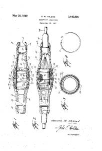
May 15, 2012 ... Wing-like portion of each clip has a pair of integral, ?exible. “Wings” extending .....
clip P10 is then bent around suitable forming tools to form the.
US008177195B2
12 United States Patent
10 Patent No.:
Schall et al. (54)
(45) Date of Patent:
CONNECTOR COMPONENTS AND
,
METHODS OF USE _
(75)
_
_
Inventors: Frederick Schall, Bngantme, N] (U S); Christopher Tromley, Penn Valley, PA
,
2 i
May 15, 2012 5111111113481 c a ................ ..
5,873,564 A *
2/1999
Bisch ........ ..
6,375,166 B1*
4/2002
Schallet a1.
6,682,056 B1 6,698,726 B2
1/2004 West 3/2004 Platt
(Us); James Jamzynski. conmgswood.
333,233 g}: ggggg glllndy d~ ~~~~ ~ 7,025,335 B2*
,
eXan
7,134,647 B2
(73) Assignee: Delair Group, LLC., Delair, NJ (US)
7,152,849 B2
(*)
7,232,114 B2 7,341,242 B2 *
Subject to any disclaimer, the term ofthis patent is extended or adjusted under 35
,
U80 1546’) by 193 days‘
(21)
APP1- NO-I 12/642,164
(22)
F1led:
(65)
Prior Publication Data Us 2011/0150566 A1 ]un_ 23’ 2011
Dec. 18, 2009
523235
..
.
4/2006 Zhu ............................... .. 256/22
11/2006 G b
12/2006 Gib: 6/2007 Platt 3/2008 Bertato .................... .. 256/65.ll
,
ihu 0 ................ ~~~~~ ..
7,819,390 B2*
'
er
. 256/65.12
............. .. 256/65.08
NJ (Us)
,
Notice:
US 8 9 177 9 195 B2
10/2010
Godwin et a1.
2009/0238640 A1*
9/2009
2010/0078614 A1
4/2010 Graber
2012/0032130 A1
2/2012
~~~~
....
.
. . . .. 256/22
Godwin et a1. ............. .. 403/329
Graber
* Cited by examiner Primary Examiner * Joshua Kennedy (74) Attorney, Agent, or Firm * Volpe and Koenig, PC.
(51) Int. Cl.
(57)
BZIF 2 7/00 (2006-01) E 04H 17/16 (2006-01) (52) US. Cl. ...................... .. 256/22; 256/65.12; 403/397
Interlocking clips are provided to assemble structures Without the need for conventional fasteners. Structures such as fences, Whiehmay be assembled in situ, include the cooperating clips
(58)
ABSTRACT
Field of Classi?cation Search ............. .. 256/ 65.02,
designed to provide a controlled amount of “play” betWeen
256/65.08, 65.11, 65.12; 403/329, 347, 397
the pickets and rails of the fence to enable adjustment When
See application ?le for complete search history.
racking the fences to accommodate sloping terrain. The clips
References Cited
preferably formed of a single sheet of a springy metallic material. The clips may be advantageously used to couple other types of apparatus.
are provided to interlock rails to cross members. The clips are
(56)
U.S. PATENT DOCUMENTS 2,218,953 A * 3,612,461 A *
10/1940 10/1971
Gustafson ..................... .. 256/22 Brown ........................ .. 248/317
130
3 Claims, 7 Drawing Sheets
@
US. Patent
May 15, 2012
Sheet 1 017
US 8,177,195 B2
Nb
m“6E
m2..GEn:.UE Oh.UE
n2..GEm“
US. Patent
May 15, 2012
Sheet 2 017
US 8,177,195 B2
P70
FIG. 1H R1
R3
R6 R4
R2
R7
FIG. 1! R5
US. Patent
May 15, 2012
Sheet 3 017
US 8,177,195 B2
US. Patent
May 15, 2012
l
Sheet 4 017
US 8,177,195 B2
l
\L _ _ _ _ _ _ _ __‘_1
I
i______:
( _ _ _ _ _ _ _ _ __,
L__.:
I I
i
\\\
=
I 1/
FIG. 2K
R4\\ i
R5
FIG. 2L
\
\l
US. Patent
May 15,2012
Sheet 5 017
US 8,177,195 B2
US. Patent
May 15, 2012
200
Sheet 6 017
120a’
120d’
FIG. 4
US 8,177,195 B2
US. Patent
May 15,2012
Sheet 7 017
US 8,177,195 B2
US 8,177,195 B2 1
2
CONNECTOR COMPONENTS AND METHODS OF USE
against the adjacent sideWall of the picket and serve to prop erly align and orient the picket so as to be substantially par allel to the rail, in cooperation With the aforesaid ?exed Wings. The integral outer edges of the clip Wings are curved to
FIELD OF INVENTION
enable relative movement betWeen rail and the picket in a
The present invention relates to components for forming
clockWise or counter-clockWise direction about a central axis
assemblies such as interlocked fence structures in situ and
of the picket opening receiving the clip projecting portion to
more particularly to components con?gured to interlock to form structures, such as fences assembled in situ and Which are con?gured to interlock Without the need for conventional fasteners.
facilitate alignment of the picket relative to the rail, for example, during racking, to accommodate a sloping terrain. The opening in the Web of the channel-shaped member has a length Which is slightly greater than the thickness of the picket measured in the direction of the length of the opening
BACKGROUND
in the Web to provide a second range of movement of the picket relative to the rail to provide still further relative move ment betWeen these tWo components to further facilitate their
Efforts to simplify assembly and in situ installation of fences and the like are Well knoWn. In addition to efforts to
achieve simpli?cation and ease of assembly of in situ instal lations, designs have been developed to eliminate the need for conventional fasteners Which add to the labor intensive aspects of assembly and installation and further detract from the esthetics of completed fence installations. For example, see US. Pat. Nos. 5,660,378, 6,375,166 and DES 573,019. US. Pat. No. 6,375,166, although eliminating the need for
conventional fasteners, nevertheless requires tedious and time consuming piercing operations at the installation site. SomeWhat similar piercing operations are required in US. Pat. No. 5,660,378.
adjustment and alignment, especially during racking. The clip is preferably made of a suitable springy metal 20
maintains linear spacing of the picket With respect to the rail, Which frictional force may, hoWever, does not impede a rack
ing operation. 25
In addition, the embodiments described therein lack the
adjustability features necessary during racking of fences in that they lack the ability to provide adjustable positioning of
ing to be less than the distance betWeen the sides of the
U-shaped projection When un?exed. 35
40
45
sideWall of the rail. The clip Wings ?rmly presses the picket against the opposite interior Wall of the rail assuring a rugged, rattle-free assembly, providing a superior holding force to lock the three components into place. The interior of the opposite sideWall of the channel-shaped member is prefer ably provided With a pair of projections Which are pressed
similar to the ?rst embodiment. A pair of integral Wings are joined to a U-shaped projection at the center of the clip. The
Wings each have curved end portions bent upWardly in the direction of the projection. The sides of the U-shaped proj ec tion are pressed together as the projection is forced into the
picket opening. The clip of the second embodiment is like 50
Wise oriented at an angle to the longitudinal axis of the picket to clear the integral ?ange at one end of the adjacent sideWall of the rail. Once clear of the ?ange, the clip realigns itself With
the picket, Whereby the bent end portions of the Wings press against the interior sideWall of the rail ?rmly locking the 55
picket and rail to one another. Similar to the ?rst embodiment,
the distance betWeen the outermost opposite edges of the
integral curved Wings is substantially equal to the distance betWeen the inWardly directed integral ?ange of the rail and
art an end of one sideWall of the rail. The Wings move partially toWards their normal, un?exed state as they pass the aforesaid
?ange but nevertheless remained ?exed due to the limited space betWeen the picket and the interior of the adjacent
surface of the rail, providing the force for locking the picket and rail together. In another embodiment, the clip, Which is also preferably formed of a springy metallic material, is utiliZed for joining larger siZe rails and pickets. The central portion of the clip is inserted into an opening in the picket at an angle in a manner
adjacent to the opening. The picket, With the clip mounted
Wing-like portion of each clip has a pair of integral, ?exible “Wings” extending outWardly on opposite sides of the sub stantially U-shaped insertion portion that extends into an opening arranged along one surface of the picket. The Wings are caused to undergo ?exing due to being pressed betWeen the picket and an integral, inWardly directed ?ange provided
In one clip embodiment, the Wings bend over on them
selves to form a substantially “R” shaped con?guration, Whereby the free ends of the Wings press against the interior
It is therefore an object of the embodiments described
thereto, and aligned at an angle to the longitudinal axis of the picket, is inserted into a region betWeen opposing sides of a channel-shaped rail so that the top of the picket extends through an opening in the Web of the channel-shaped rail. The
and to ?rmly secure the clip to the picket due to the sides of the
U-shaped projection being ?exed toWard one another, by con?guring the distance betWeen the sides of the picket open
SUMMARY
herein to provide components con?gured to provide ease of in situ assembly and installation of components Which provide a rugged, rattle-free structure Without the need for conventional fasteners. The fence of one embodiment utiliZes clips having an insertion portion initially inserted into an opening in a picket and a Wing-like portion for engaging a face of the picket
Opposite edges of the clip Wings are of a length measured in the direction of the longitudinal axis of the picket, Which is substantially equal to the distance betWeen a supporting sur face of the inWardly directed ?ange and the interior surface of the Web of the rail, trapping the clip betWeen these tWo sur
faces, to prevent disengagement of the rail, clip and picket, 30
the fence components relative to one another to accommodate
a sloping terrain, While at the same time, providing rugged, rattle-free and structurally strong fence assemblies While per mitting several degrees of relative movement of the compo nents, While eliminating the need for conventional fasteners.
Which ?exes during insertion into the rail and exerts a strong spring force on the rail, creating a frictional locking force that
the interior surface of the yoke, serving as a positive stop to 60
65
lock the clip into the rail. The outWardly bent portions of the Wings partially snap back toWard their normal un?exed state as they pass the ?ange on the rail. The clip ?rmly secures the picket to the rail. The sides of the projection portion of the clip con?gured for insertion into an opening in the picket are bent to substantially form a V-shape. The vertexes of the V-shaped projection extends into the interior of the opening in the
picket to aid in retaining the clip in place in the picket.
US 8,177,195 B2 3
4
In still another clip embodiment, the Wings are joined to the V-shaped portion con?gured for insertion into an opening in a picket. Inner ends of the Wings are integrally joined to the
FIG. 2E is a top vieW ofthe clip of FIG. 2A. FIG. 2F is a vieW of the embodiment of FIGS. 2A-2D looking in the direction of arroWs 2F-2F in FIG. 2E. FIG. 2G is a left-side vieW of the clip of FIGS. 2A-2D looking in the direction of arroWs 2G-2G of FIG. 2F. FIG. 2H is a right-hand vieW of the clip of FIGS. 2A-2D looking in the direction of arroWs 2H-2H in FIG. 2F. FIG. 2I is a bottom vieW of the clip of FIGS. 2A-2D. FIG. 2] is a vieW ofthe clip ofFIGS. 2A-2D looking in the
V- shaped projection portion and extend doWnWardly and aWay from the V-shaped projection, each forming a ?rst V-shaped bend forming an angle of greater than 90 degrees With the adjacent side of the V-shaped projection portion. The inner ends are bent a spaced distance aWay from the ?rst
V-shaped bend to form a second V-shaped con?guration hav ing a vertex Which is a given distance beloW the vertex of the ?rst V-shaped bend. The outer ends of the Wings are bent to form a curve about midway over their length and each de?ne
direction of arroWs 21-2] of FIG. 2B.
FIGS. 2K, 2L, 2M and 2N are plan vieWs shoWing the manner in Which the clip of FIG. 2H is produced. FIGS. 3A and 3B are exploded perspective vieWs shoWing
an outer section Which extends over its associated inner end
and curves upWardly and aWay from its associated inner end. The distance betWeen the tips of the outer ends of the Wings and the vertex at the second V-shaped con?guration is chosen
the manner in Which a picket is assembled to a rail employing
the clip embodiment of FIG. 1A.
to accommodate picket and rail designs Which create larger gap spaces betWeen a sideWall of the picket and the interior surface of an adjacent sideWall in the rail. In order to accom
modate a given gap space created by the pickets and rails used in a given installation, the angle of the ?rst V-shaped bend may be made larger and/or the length of the curved outer ends of the Wings may be increased to increase the distance betWeen the vertex of the second V- shaped bend and tip of the adjacent outer end of the Wing. Although the above embodiments set forth applications for picket fences, other applications such as ladders and other structural members may utiliZe the design of the aforesaid embodiment to great advantage. The embodiments described above are preferably formed from a single sheet of a springy metallic material, Which is cut, machined or otherWise stamped from the sheet and then
bent to form the yieldable central, U-shaped projection hav ing a pair of outWardly extending yieldable Wings. The springy material is chosen to provide a superior spring force Which is able to retain the picket, rail and clip locked together.
20
FIG. 3C is a sectional vieW of the assembly of FIG. 3A looking in the direction of arroWs 3C-3C. FIG. 3D is a sectional vieW of the assembly of FIG. 3A looking in the direction of arroWs 3D-3D. FIG. 4 is an explodedperspective vieW shoWing the manner in Which a picket is assembled to a rail employing the clip embodiment of FIG. 2A. FIG. 5 is a plan vieW shoWing a fence installation of the present invention on a sloping terrain to facilitate an under
25
standing of “racking”. FIG. 6A is an exploded perspective vieW of a fence shoW ing the manner in Which multiple clips and rails are mounted
to pickets. FIG. 6B is a sectional vieW of the fence of FIG. 6A taken 30
through one of the pickets. DETAILED DESCRIPTION OF THE PREFERRED EMBODIMENTS
35
FIGS. 1A-1G shoW the ?rst clip embodiment 10, Which is preferably cut or stamped out of a single sheet of a metallic
As an alternative, the clips of any of the embodiments herein
material having the requisite ?exibility and springiness Which
may be produced by molding them from a suitable plastic/
is, for example, stainless steel. The clip is then bent so that the central portion 10a of clip 10 has a substantially U-shaped con?guration de?ned by curved portion 10b and sides 10c and 10d integrally joined to curved portion 10b. The free ends
resin. The assembly can be performed With ease and elimi nates the need for conventional fasteners.
40
BRIEF DESCRIPTION OF THE DRAWINGS
Various embodiments and objectives of the present inven tion Will be best understood from a consideration of the
45
of the sides 10c and 10d are respectively bent outWardly and aWay from the central axis A to provide a pair of Wings 10g and 10h extending outWardly aWay from one another. Wings 10g and 10h are then bent at 101' and 10j to form smoothly
curved portions 101' and 10j, the Wings 10g and 10h being
detailed description and draWings in Which: FIGS. 1A and 1B are perspective vieWs of one embodiment
further bent at 10k and 10! providing free ends 10m and 1011
of the present invention vieWed from tWo different angles. FIG. 1C is a top vieW of the clip in FIG. 1A. FIG. 1D is a vieW of the clip of FIGS. 1A and 1B looking
Which, in FIG. 1C can be seen to form an acute angle With the 50
the curved portions 10r and 10s of main Wing portion 10h are
in the direction of arroWs 1D-1D in FIG. 1C.
FIG. IE is a vieW ofthe clip ofFIGS. 1A and 1B looking in
equidistant from an imaginary center C so that the distance
the direction of arroWs 1E-1E in FIG. 1C.
FIG. IE is a vieW ofthe clip ofFIGS. 1A and 1B looking in the direction of arroWs 1F-1F in FIG. 1C.
main Wing portions 10g and 10h. The curved portions 10q-10p of main Wing portion 10g and
55
measured along an imaginary diameter is substantially con stant and equal to a distance D1, Which design feature Will be best understood in consideration of the assembled compo
FIG. 1G is a vieW of the clip of FIGS. 1A and 1B looking
nents, i.e., the assembled picket, rail and cooperating clip, as
in the direction of arroWs 1G-1G in FIG. 1C. FIGS. 1H and II are plan vieWs shoWing the manner in
described beloW. As Was set forth above, the springy metallic clip 10 has the
Which the clip in FIG. 1A is produced. FIGS. 1], 1K and IL respectively are front elevational,
capability of ?exing due to the application of force and of 60
example, sides 10c and 10d of the curved portion 10a of clip
bottom and left-side elevational vieWs of a clip Which is a
modi?ed version of the clip of FIGS. 1A-1I. FIG. 1M is a plan vieW shoWing the clip of FIGS. 1J-1L
10 are designed and con?gured to ?ex and move toWards one
another upon the application of an appropriate force. Simi larly, free ends 10m and 1011 Will ?ex and thereby move
before being formed into its ?nal con?guration. FIGS. 2A-2D are perspective vieWs shoWing another embodiment of the clip of the present invention vieWed from
various angles.
returning to its un?exed state upon removal of such force. For
65
toWard main Wing portions 10g and 10h upon the application of an appropriate force and Will likeWise return to their relaxed state upon the removal of the said force.
US 8,177,195 B2 6
5 In one preferred method for producing clips 10, a clip
relative to the picket or both picket and rail may be moved
pattern P10 is stamped or otherwise cut from a ?at sheet S10 of a springy metallic material, such as stainless steel, as
picket surface 110a and the free end of ?ange 120e to move
during this assembly. There is suf?cient clearance betWeen
shoWn in FIG. 1H, to provide the planar clip P10. The planar
the tips 10q, 10r of clip 10 into the gap region G to enable the clip to be moved upWard together With picket 110. Before the picket 110 enters into gap G, the tips T1, T2 of the free ends 10m, 1011 of clip 10 (Note, also FIG. 1G) rest against surface 11011 of picket 110 and are substantially in the relaxed, i.e., un?exed, state. As clip 10 moves upWardly and tips 10q, 10r enter into gap G, ?ange 120e slidingly engages the clip caus
clip P10 is then bent around suitable forming tools to form the desired curvatures at regions R1-R6, the related curvatures
resulting from the bending operations being shoWn in FIG. 11. FIGS. 1], 1K and IL shoW a clip embodiment 10' Which is
a modi?cation of clip 10, like portions of clip 10 and clip 10' being identi?ed by like numerals except that portions in FIGS. 1J-1L are identi?ed With primes. The angle Q‘ formed
ing the bottom end of clip 10 to move toWard surface 11011 of
betWeen clip portions 10c'-10g' and 10d'-10h' are greater than the angle Q‘ formed betWeen clip portions 100-10g and 10d 10h of clip 10. The Wings of clip 10' are bent to provide
picket 110, the top edges 10q, 10r serving as a pivot about Which clip 10 rotates. This action moves the U-shaped portion 10a of clip 10 more deeply into the opening 110e, causing clip sideWalls 10c, 10d (Note, especially FIGS. 1C and 3C) to
vertices 10Z'-10u' and the outer ends 10k'-10l' are curved
upWardly from curved portions 10i'-10j' of clip 10'. It can be
move toWard one another and further causing the portions
seen from a comparison of clips 10 and 10' that the distance D measured from the vertices 10Z'-10u' to their associated free ends 10v-10w is greater than the distances measured from the
free ends of the portions 10k-10l to the portions 10g-10h of
10m, 1011 ofclip 10 to ?ex in the direction ofportions 10g, 10h
respectively, of clip 10. During this time clip 10 urges picket 20
clip 10, enabling the employment of clip 10' in installations using pickets and rails that create a larger gap space in the
region Which receives the clip. The distance D canbe adjusted by adjusting one or more of: the angle Q‘; the length of clip portions 10k'-10l' and the location of vertices along clip por
1 10 to move in the horiZontal, left-hand direction as shoWn by
arroW B to urge surface 1100 of picket 110 against alignment rib 120d of rail 120. The angle 6 betWeen clip 10 and picket 110 continues to be reduced toWard Zero degrees as the clip 10 moves further into the interior of rail 120 until the loWer edges 25
tions 10g'-10h'.
10p, 10s (Note, also FIG. 1D) clear ?ange 120e, Whereupon the clip 10, due to the spring forces of the U-shaped portion 10a and portions 10m, 1011, urge portions 10g, 10h of clip 10 against the interior surface 120g of sideWall 1201) (see FIG.
The clip embodiment 1 0' may be manufactured in a manner
similarto the clips 10 and 20. FIG. 1M shoWs the clip 10' after
3C).
it has been stamped or cut out of a ?at sheet of springy
metallic material. The clip is then bent into the proper shape as shoWn in FIGS. 1J-1L employing suitable forming tools. FIG. 3A is an exploded perspective vieW of the clip of FIGS. 1A-1G shoWing the manner in Which the clip mounts betWeen a rail and a picket. The exploded assembly 100 comprises a channel-shaped mid-rail 120 having a Web por tion 120a and tWo (2) integral sideWalls 120b, 1200. SideWall 12019 has an integral alignment rib 120d extending along the length of sideWall 120b. SideWall 1200 has an integral, inWardly directed ?ange 120e along the bottom free end of
30
The distance betWeen the opposing edges 10q, 10s and 10r, 10p is substantially equal to the distance betWeen ?ange 120e and the interior surface 1201' of Web portion 120a of rail 120 thereby con?ning clip 10 betWeen ?ange 120e and the interior surface 120i, preventing the clip 10 and picket 110 from
35
moving upWardly or doWnWardly relative to rail 120. The spring force of clip 10 urges picket 110 aWay from sideWall
sideWall 1200. An opening 120f is provided in Web portion
40
1200 and against the alignment rib 120d and the edge 120f-1 of opening 120f to maintain the picket in parallel With side
12011 of rail 120, Which conforms to the rectangular, cross
sectional shape of the picket (preferably although not neces
sarily rectangular). Picket 110 is a holloW, rectangular-shaped, elongated member de?ned by four (4) sideWalls 110a, 110b, 1100 and 110d. SideWall 11011 is provided With an opening 110e for
45
Wall 1201) and further to prevent movement of picket 110 either leftWardly or rightWardly in the horiZontal direction relative to rail 120. The springy material of Which the clip is formed is chosen to provide a spring force Which is more than
adequate to achieve the above objectives. As can clearly be seen, rail 120 completely conceals clip 10 from vieW, When fully assembled. The top rail 130 is mounted to the picket 110 using a clip 10
receiving the substantially U-shaped projection 10a of clip
in a similar fashion to that shoWn in FIGS. 3A and 3B, the
10. The dimensional relationship of opening 110e relative to
difference being that the top end of the picket is retained Within the top rail 130. Making reference to FIGS. 2A-2J, the more rugged clip embodiment 20 shoWn therein is comprised of a substantially U-shapedportion 2011 having a curved central portion 20b and integral arms 20c, 20d. Clip 20 is bent to form comers 20], 202
the substantially U-shaped projection 10a is such that the curved tip is substantially free to enter opening 110e and, as
50
the U-shaped projection 10a is pressed into the opening, the gradually increased spacing betWeen sides 10c and 10d in the unstressed state becomes greater than the Width of opening 110e in the horiZontal direction, causing the sides 10c and 10d of the ?exible clip to be pressed toWard one another and
and 20g, 20e. The outWard portions 201', 20a extending from 55
undergo ?exing.
respectively.
Clip 10, after being at least partially inserted into opening
In the manner similar to the clip embodiment 10, clip
110e, is oriented at an angle 6 to surface 110a ofpicket110 as shoWn in FIGS. 3B and 3D. Clip 10 is oriented at an angle 6
to bring the upWard edges 10q, 10r into engagement With
embodiment 20 Which is likeWise formed of a suitable 60
surface 11011 of picket 110. The upper end of picket 110 is placed betWeen sideWalls 120b, 1200 of central rail 120 and moved upWardly in the direction shoWn by arroW A so that the upper end of picket 120 enters into opening 120f and moves further in the direc tionA relative to the rail 120. It should be understood that the
picket may be held stationary and the rail moved doWnWardly
corners 20g, 20e respectively are further bent to form curved
portions 20!, 20j Which terminate in end portions 20m, 20k
65
springy material, is con?gured to have its sideWall portions 20c, 20d ?exed inWardly as it is pressed into the opening 1200' have its portions 201', 20a curve portions 20!, 20j are likeWise to be ?exed from the relaxed position to provide a holding force suitable to retain the picket Within the rail to Which it is inserted in the manner similar to clip 10 and thereby provide assembly in Which picket 120' is locked to rail 110' in a rugged and rattle free manner.
US 8,177,195 B2 8
7
version Which is obtained by virtue of its different con?gu ration as compared With clip embodiment 10. If desired, clips
Both of the clip embodiments 10 and 20 are further capable
of yielding to permit raking of the fence Which is described beloW With reference to FIG. 5.
20 may be formed of a thicker metallic sheet or be formed of a metallic material providing an increased spring force, or both. FIG. 5 is a vieW of a portion of a fence employing the clips
FIGS. 2K-2M show a preferred method for producing clip 20. Similar to the description of FIGS. 2H-2l, a clip pattern P20 is stamped out of sheet S20 of a springy metallic material. The planar clip P20 is bent around suitable forming tools to form the desired curvatures at regions Rl-RS, the resulting curvatures being shoWn in FIGS. 2L-2M. Making reference to FIG. 4, there is shoWn an assembly
of the embodiment shoWn in FIG. 1A, the fence being installed to extend along a level terrain T1 and an adjacent
sloping terrain T2. Adjacent ends of the rails 130, 130' are joined to a post P at the location Where the level and sloping terrains meet. Although the pickets 110 are maintained in a
200, comprised of a rail 120' and a picket 110' Which are
vertical orientation along both the level and sloping terrains,
substantially similar to the assembly 100 of FIGS. 3A and 3B but of a larger siZe and adapted for heavy duty use such as industrial or commercial applications. As a result, the rail and picket are identi?ed With prime numbers to differentiate them from the rail 110 and picket 120 and 120 as shoWn in FIGS. 3A and 3B. The heavy-duty clip embodiment 20 shoWn in FIG. 4 has
the rails 130, 130' are arranged so as to be substantially
parallel to their respective terrains. Nevertheless, the clips 10 are maintained so that their central axes are aligned With the
its substantially U-shaped projection 20a inserted into open ing 110e' and aligned at an angle to the picket in a manner
20
substantially similar to that shoWn in FIG. 3A, Wherein clip 20 is aligned so that its longitudinal axis forms an angle 6 With surface 11011‘ of picket 110'. As Was described above regard ing assembly 100, as shoWn in FIGS. 3A and 3B, opening 110e is of a siZe relative to clip 20 so that the sideWalls of U-shaped portion 20d are ?exed and moved toWard one
25
to prevent rattling of the fence, even When mounted on a
sloping terrain.
another as the substantially U-shaped projection 20a is inserted more deeply into opening 110e’. Clip 20 is oriented at an angle 6 to surface 11011‘ of picket 110' so that the upper most edges 20n, 20p ofclip 20 (see also FIG. 2F) engage surface 11011‘ of picket 110' and further so that the bent free ends 20m, 20kalso engage the surface 110a’. Similar to the embodiment shoWn in FIGS. 3A and 3B, the
30
rail 120'. The top end of picket 110' passes through opening 120]‘r and clip 20 changes its orientation relative to surface 110a‘ Whereby the loWer end of clip 20 sWings toWards sur face 110a', With edges 20n, 20p serving as pivots about Which clip 20 rotates.
FIG. 6A is a perspective vieW showing a partial fence
assembly employing the clips 10, each picket 110 receiving 35
40
45
loWer ends 20q, 20r of clip 20. When the loWer tips 20q, 204 clear ?ange 120e', clip 20 snaps into position so that its outside corners 20g, 20e are in intimate engagement With the 50
1. Apparatus comprising: of integral sideWalls extending from the Web portion; said Web portion having at least one opening; a cross member inserted betWeen said sideWalls and having
55
The distance betWeen upper tips 20n, 20p and the loWer tips 20q, 20r is substantially equal to the distance betWeen ?ange 120e' and the interior surface 1201" of Web portion 120a‘, causing the entire length of the outside corners 20g, 20e to rest against the interior surface 120g‘ of rail sideWall 1200' and further assuring that clip 20 is locked in place betWeen inte rior surface 120g‘ and ?ange 120e' and that the picket 110' is maintained substantially parallel to the sideWall 12019‘ of rail 120'. The clip embodiment 20 has all of the advantageous features of the clip embodiment 10 With the understanding that the clip embodiment 20 is a more rugged, heavy-duty
The array C2 of clips 10 for retaining the top rail 130 are then inserted in pickets 110 provided closer to the upper ends of the pickets 110. The top rail 130 is slid doWnWardly over the top of the pickets 120 to lock the clips 10 in array C2 into place. All of the clips in arrays C1 and C2 are locked into place in the manner shoWn in the sectional vieW of FIG. 6B. What is claimed is: a channel-shaped member having a Web portion and a pair
120d‘ and edge 120f-1' of opening 120]‘, portions 20!, 20j serving to press surface 1100' of picket 110 into ?rm engage ment With rib 120d‘ and edge 120fl1', 110e' Which also serves to press the vertices 20q, 20r into intimate engagement With the interior surface 120g‘ of the rail sideWall 1200’.
the mid-fence rail 120 are ?rst mounted on the pickets in the tilted manner described above regarding FIGS. 3A and 3B, after Which rail 120 is moved doWnWardly to receive the
pickets through openings 120f and then to receive and cover the array C1 of clips 10 for retaining rail 120 to pickets 110.
through opening 120]’, curved portions 20!, 20j are caused to
interior surface 120g‘ of sideWall 12c‘ and, similar to the embodiment 100 shoWn in FIGS. 3A and 3B, surface 1100' of picket 110' is in intimate engagement With alignment rib
tWo (2) clips to accommodate a mid-fence rail 120 substan tially the same as shoWn in FIG. 3A, and a top rail 130 also shoWn in FIG. 3A. Rectangular slots 110e are formed in the
pickets (see FIG. 3A). The array C1 of clips 10 for retaining
As the picket moves more deeply into the region betWeen sideWalls 12019‘ and 1200' and has its top end extending ?ex so that the tips 20m, 20k move in a direction toWard the
The clip embodiment 20 of FIG. 2 is provided With simi larly curved top and bottom edges to permit racking as Well as assuring that the rails are ?rmly locked to the pickets and to provide a rattle-free fence.
edges 20n, 20p easily enter the gap region G' betWeen the outer most edge of ?ange 120e' and surface 11011‘ as the picket 120' is moved upWardly betWeen sideWalls 12019‘ and 1200' of
longitudinal axes of their associated pickets 110, the rail 130' is oriented so that it deviates from being perpendicular to the central axes of the pickets and the clips, Which type of instal lation is referred to as “racking.” By providing the top and bottom edges of the clips With a convex curvature, making reference to FIG. 1D, the distance measured along imaginary diameters such as D2 and D3, for example, is constant and equal to D1, Which is substantially the same as the distance betWeen the ?ange 120e and the interior surface of the Web portion 12011, to ?rmly lock the rails to the pickets and further
a ?rst end extending at least partially through said open ing, longitudinal axes of said cross member and said channel-shaped member being transverse to one
another; a stabiliZing rib integral With and extending inWardly from 60
said ?rst sideWall and engaging a ?rst surface of said cross member;
65
a ?ange integral With and extending inWardly from a free end of said second sideWall; a clip having a substantially U-shaped central portion de?ned by ?rst and second sideWalls joined to a curved
end portion, said central portion extending inWardly into an opening in a second surface of said cross member
US 8,177,195 B2 9 opposite said ?rst surface, the ?rst and second sidewalls of said U-shaped central portion being urged toWard one another as the U-shaped central portion is pressed into
said opening; free ends of said U-shaped central portion ?rst and second sideWalls being bent a given distance from the curved end portion to form a pair of Wing portions extending aWay from one another and being provided With curved bends to form free ends Which extend toWard the curved
central portion, the free ends forming an angle of less than 90° With the Wing portions; said free ends being urged into intimate contact With the second surface of said cross member and said Wing
portions being urged into intimate contact With an inte rior surface of said second sideWall Whereby said clip urges a ?rst surface of said cross member into intimate
contact With the stabiliZing rib and an edge of the open
ing in the rail thereby maintaining the channel-shaped member, cross member and clip into intimate locking
engagement.
10 2. The apparatus of claim 1, Wherein a distance of opposing
edges of said ?rst and second Wing portions are substantially equal to a distance betWeen the integral ?ange of the second sideWall of said channel-shaped member and an interior sur
face of said Web to retain the clip in the channel-shaped member. 3. The apparatus of claim 1, Wherein opposite edges of said ?rst and second Wing portions are curved and the distance measured along a diameter passing through a central point of the clip is substantially equal to a distance betWeen the ?ange on the second sideWall of the channel-shaped member and an
interior surface of the Web portion of the channel-shaped member to retain the clip in place even in the event that a
longitudinal axis of the channel-shaped member deviates from being perpendicular to axis of the clip.