Fakult¨at fu¨r Informatik
CSR-09-05
Considerations on Technical Sketch Generation from 3D Scanned Cultural Heritage
Christian H¨orr · Elisabeth Lindinger · Guido Brunnett
September 2009
Chemnitzer Informatik-Berichte
Considerations on Technical Sketch Generation from 3D Scanned Cultural Heritage Christian H¨ orr1 , Elisabeth Lindinger2 , and Guido Brunnett1 1
2
Chemnitz University of Technology, Germany {hoerr, brunnett}@cs.tu-chemnitz.de Archaeological Heritage Service of Saxony, Dresden, Germany
[email protected]
Summary. Drawing sketches is certainly one of the most important but at the same time elaborate parts of archaeological work. Currently, 3D scanning technology is affording a number of new applications, and only one of them is using virtual copies instead of the originals as the basis for documentation. Our major contribution are methods for automatically generating stylized images from 3D models. These are not only intuitive and easy to read but also more objective and accurate than traditional drawings. Besides some other useful tools we show several examples from our daily work proving that the system accelerates the whole documentation process considerably. Key words: automated documentation, non-photorealistic rendering, 3D scanning.
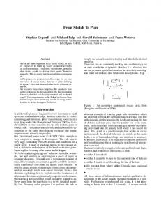
1 Problem Statement Due to the increasing number of large-scale excavations, every institution concerned with cultural heritage is faced with an enormous amount of finds. In the federal state of Saxony alone, the archaeological archive is currently containing almost 20,000,000 objects, mostly pottery from the Neolithic to modern times, and their number is annually increasing by another 700,000. All these objects are of little use if they are only put into storage instead of being prepared for scientific evaluation and interpretation. Only material that is published can finally contribute to archaeological knowledge. Within the documentation process, creating graphical illustrations is certainly one of the most laborious tasks of archaeological work, and it consumes the major part of the available, but always precious time. Yet for drawing ordinary objects about an hour of work can be assessed, and the effort can quickly increase up to several days for really complex ones, such as the beaker in fig. 1. Our aim is therefore to accelerate the whole workflow by deriving measures and figures directly from the geometry of 3D scanned models. Not only that this shortens the time usually spent on the publication of archaeological finds dramatically, it even improves the quality of the documentation results in terms of accuracy and objectivity.
2
Christian H¨ orr, Elisabeth Lindinger, and Guido Brunnett
(a)
(b)
(c)
Fig. 1. Comparison of (a) traditional drawing, (b) revised drawing and (c) nonphotorealistically rendered image of a Corded Ware beaker. The latter was used as a template for (b), but still the differences among the images are striking, particularly concerning the rim part, the decoration, the silhouette and the overall plasticity. While (a) and (b) took hours to be drawn, the rendered image was generated within a few seconds and many more of them could be added if necessary.
The paper is organized as follows: At first, we briefly summarize the requirements of conventional drawings, their benefits and deficiencies. Afterwards, we discuss some practical aspects of the scanning process for achieving the best results. Section 4 is dedicated to several applications arising from the existence of virtual copies, including automated measurement, photorealistic and non-photorealistic rendering, vessel unrollings and profile generation. Giving some exemplary results in section 5, we show advantages and limitations of the presented system.
2 Traditional Documentation Among the different techniques for the documentation of archaeological finds, without doubt manually drawn technical sketches are most prevalent. At the same time they convey information about many different properties such as shape, manufacturing process, surface treatment, ornamentation, and state of preservation. These images are intended to be read easily and quickly and are therefore highly abstracted. Usually only as little time as necessary is spent on their production, what is often another source for the loss of information. In order to keep printing costs low the images are generally restricted to blackand-white colour, and of course, they need to be undistorted and true to scale. Even if the sketches are drawn as fast as possible, before being ready for printing there are many different steps of work to each of them: 1. The object’s outline is drawn with a pencil. If present, paintings, ornamentations and breaking edges are added. 2. The image is copied with ink and at will is also given a plastic impression by schematic shading of the object’s surface (stippling, pointillism, hatching, etc.). 3. The scientific editor revises the image and if necessary, corrections are made.
Considerations on Technical Sketch Generation from 3D Scanned CH
3
4. The ink drawing is digitized with a flat-bed scanner. 5. The image is post-processed and possibly vectorized. However carefully the sketches are drawn, they are still drawn by hand and are thus susceptible to the illustrator’s individual skill. If one and the same object was to be drawn by several illustrators, the results would exhibit not only negligible but striking differences (cf. fig. 1 and e.g. Orton et al. 1993, 93, fig. 7.3). While sketching, the draughtsman has to decide which properties of an object are important to depict and which are dispensable information. Of course, this process of abstraction and simplification remains untraceable for the viewer and can easily convey an impression different from that of the original find. So far, there are no comprehensive rules or conventions that apply to technical illustration in archaeology in general, although this would simplify the understanding of the sketches a lot and therefore would be of great importance. If there are any conventions at all, they are usually restricted to single research institutions or publication series (cf. e.g. Czysz et al. 2007). Hence, a lot of different drawing styles have evolved in the past that are almost impossible to make consistent. The helplessness of some major institutions faced with this situation is for example clearly displayed in the vague illustration guidelines of the Roman-Germanic Commission (RGK 1990). There are hardly any alternatives to technical illustration. In order to rule out subjectivity, photography might serve as a convenient option. It is used for documenting selected finds such as elaborately decorated, especially painted vessels where a manual sketch would take even longer to create than usual. Still, there are several disadvantages to photographs: Depending on the shape of the object and the focal length of the lens, the image can be strongly distorted. Additionally, illumination often causes highlights on polished or glossy surfaces so that details in these parts may disappear. Finally, the virtual reconstruction of complete vessels out of single fragments, which is comparatively easy in an illustration, is hardly possible to achieve by means of photography.
First Approaches Towards Automation A new device called “profilograph” has been developed by Smilansky et al. (Watzman 2004). It allows the user to digitize profile lines of single sherds by pointwise mechanical or optical measurement. If the sherds have been correctly aligned with respect to the rotational axis previously, a highly stylized 2D sketch can be computed. Though the method has successfully contributed to develop vessel typologies on the basis of the profiles of rim sherds (Gilboa et al. 2004), it is questionable if it can really accelerate traditional documentation or even replace it completely. According to Karasik and Smilansky (2008) in the meanwhile this research group has switched over to 3D scanners as well. Another application has recently been presented by Mara et al. (2007), where painted Attic pottery is captured with a 3D scanner and the surface colour is analyzed by a multispectral camera. Profiles and silhouettes are directly extracted from the 3D meshes and serve as templates for the generation of figures meeting the requirements of the Corpus Vasorum Antiquorum series. However, this approach is not yet able to also display surface structure.
4
Christian H¨ orr, Elisabeth Lindinger, and Guido Brunnett
3 Data Acquisition: Practical Issues During the past years, several range scanning techniques have conquered archaeology. Terrestrial scanners have been followed by object scanners, and for both a multitude of applications has emerged. Current devices are able to measure objects with a point distance of less than 0.2 mm down to a few microns, what is even more than a human eye is able to resolve. In this respect, their quality has become good enough to use the virtual copies instead of the originals as the basis for documentation. The advantages coming along with this approach are numerous: The original objects are protected by minimizing physical contact, they become spatially independent, and reconstructions can be carried out completely in virtual space saving storage capacities too. In our laboratory we are currently employing the Konica Minolta VI-910 laser scanner which was one of the first to also capture the colour of the surface. Compared to some newer devices, its optical and texture resolution are rather low, but for the majority of objects it is still sufficient. In order to ensure constant and optimal lighting conditions, we illuminate the object to be scanned with two diffuse daylight bulbs. To rule out any influence of stray light, we first shielded the whole set-up with a box of black molleton as it is commonly done by photographers. Experience however showed, that this enhances shades on the object that make the registration of colour values difficult. Due to this, we decided to line the box with white sheets that give a soft reflection of light all over the object’s surface. Anyway, a genuine rendition of colour cannot be guaranteed by any device and so the aim should be at least to establish uniform lighting conditions rather than trying to capture the actual colour. One of our major concerns on this topic is that comparability gets lost which is probably even more important than accuracy. Moreover, as the colour of unpainted objects is rarely of interest and not depicted in technical illustrations, this does not pose a real problem. In the few cases in which the surface colour was needed, we texturized the 3D model with a high resolution, true-to-colour digital photo by using a colour chart as well. For our work, aside from closing small holes in the triangular meshes any attempts to improve the 3D models after the scanning process, in particular by smoothing the surface, have proven to be of no or only little use. Additionally, any subsequent changes only affect the scanning result as they remain untraceable – a matter being also discussed in the London Charter (www.londoncharter.org). Nonetheless, we can state that the better the data, the better the documentation results. However, data quality also depends highly on the object’s texture and material. We got the best results on non-shiny, moderately bright materials, e.g. unglazed ceramics, organic materials such as wood and bones, many kinds of rocks and corroded metal (see section 5). At least in some cases a matting spray can be applied, provided that it is chemically harmless and the surface colour is not of interest. In order to accelerate the scanning process we also employ a motorized turntable, since it enables us to produce entire series of scans in one step that are already correctly aligned. This shortens acquisition time a lot, and so up to 30 pots can be digitized within an eight hour working day. For the quick scanning of a few single sherds at once, Karasik and Smilansky clip them on a framework mounted to the turntable (2008, 1150f). Thus, according to them actually several hundred sherds can be scanned per day.
Considerations on Technical Sketch Generation from 3D Scanned CH
5
4 Using 3D Models for Automated Documentation Since our focus of interest is currently on ancient ceramics, in the following some presumptions and prerequisites are derived from the specific demands of pottery documentation. However, most of the proposals apply for other types of artefacts as well.
4.1 Measures Once having a three-dimensional virtual copy of an object, taking measures is relatively simple. Within seconds many arbitrary distances can be computed by just clicking two points on the object’s surface. Depending on the point cloud density and the scanner’s resolution, usually a much higher accuracy compared to manual measurement by rulers and callipers can be achieved. In the special case of vessels we can introduce some automatism by making use of their rotational symmetry. Estimating the rotational axis has previously been tried by several research groups (e.g. Karasik and Smilansky 2008 and references therein; Wagner et al. 2008), but in fact objects are rather put upright onto their base surface in case it is preserved. We therefore developed a specific algorithm detecting the base plane which we leave out here for reasons of space. As soon as the vessel (or sherd) is correctly aligned, several heights and diameters can be extracted either directly from the 3D mesh or from some selected profiles. As we have already shown in recent publications, measuring vessels automatically can particularly contribute to similarity estimation (H¨ orr and Brunnett 2008) and automated classification (H¨ orr et al. 2008).
4.2 Stylized Figures Limitations of Line Drawings When creating stylized drawings directly from 3D models the question is raised, how accurate the traditional sketches could and should be reproduced. In the computer graphics literature, recently many proposals for line drawings have been made, e.g. suggestive contours (DeCarlo et al. 2003) which, according to Ma and Zha (2006), do not meet the requirements of archaeological drawings yet, as well as highlight lines (DeCarlo et al. 2007), apparent ridges (Judd et al. 2007) and lines from diffuse shading (Lee et al. 2007). But as it is shown in an interesting study by Cole et al. (2008), none of them regards all aspects of human drawings. Basically, the main issue in this topic is, when a feature is considered significant enough to be emphasized by a line. Without doubt, this is a matter of subjectivity. Furthermore, since there are so many different drawing conventions in archaeology, it seems nearly impossible to create a style that is common to everyone. Consequently, we came to the conclusion that if a new technique has to be developed anyway, there is no need to intentionally simulate a loss of information coming along with every kind of abstracted line drawing. Nevertheless, at least the object’s silhouette should be depicted, since it is probably the most important element to convey shape. For its computation we refer to the overview paper of Isenberg et al. (2003).
6
Christian H¨ orr, Elisabeth Lindinger, and Guido Brunnett
An intuitive rendering style being not too far away from pencil drawings should at the same time convey a high level of detail and a plastic impression caused by a lightsource placed in northwestern direction. In the next two sections we discuss both issues separately.
Lighting Models For the sake of simplification, in the following we assume to illuminate a sphere with poles being defined by the lighting direction and the equator being defined as the set of points whose surface normals are perpendicular to the lighting direction. The lighting direction splits the sphere into a frontfacing (“dayside”) and a backfacing hemisphere (“nightside”). Unless otherwise stated, we place the lightsource at an azimuth and zenith of both 45◦ , simulating the traditional over-the-shoulder lighting. The probably most employed lighting model throughout computer graphics was introduced by Phong in 1975. He splits the light reflected by a surface into an ambient, diffuse and specular term. While the ambient light causes an omnipresent, but usually moderate basic luminance by simulating perfectly diffuse lighting from all directions, the diffuse term is responsible for the basic lighting gradient on the frontfacing hemisphere according to the Lambertian cosine law. Additionally, for objects with very smooth materials such as polished metal the specular term causes view-dependent highlights (fig. 2(a)). In technical sketches however, these would only distract the viewer from interesting details and should therefore be avoided. In Phong’s lighting model the backfacing hemisphere is brightened up only by the ambient term. In order to simulate a more balanced lighting situation we extend the lighting gradient so that it is ranging from pole to pole. This lighting model is still artificial but it gets much closer to reality, where indirect lighting is the much more frequent case than direct lighting. As it can be seen from fig. 2(b) two of the approach’s disadvantages are the very low local contrast and the overexposure around the lit pole. An enhancement of contrast could be achieved by simply squaring the intensity either of the Phong model or the smooth diffuse gradient. In both cases lighting from northwest causes a very dark area in the lower right part of the sphere, and this would also apply for bellied vessels. Therefore, only a headlight from the viewer’s position illuminates the object strong enough. The result is an unfamiliar, but kind of dramatic view (fig. 2(c)) which may have applications in some niches. At least, it underlines the object’s silhouette and some surface details. In order to enhance the local contrast but still to convey information about the lower right part, we tried to place a second, slightly weaker light source opposite to the first one (Gooch et al. 1998). This yields a shading that is sometimes used in cartoons, but at the same time it causes cords near the equator (fig. 2(d)). All the lighting models mentioned above compute luminance only as a local property. As a result, global influences, particularly indirect lighting are only approximated or not considered at all. In cases where a photorealistic image rather than a technical sketch is wanted, but photography is unsuitable due to the mentioned shortcomings, more sophisticated rendering techniques such as raytracing or radiosity could be a way out (fig. 3). Because of their algorithmic complexity these methods do not allow realtime interaction, but the results speak for themselves. Although they might not be suited for scientific documentation purposes in general, they could at least give some new impulses to illustrations in popular science.
Considerations on Technical Sketch Generation from 3D Scanned CH
(a)
(b)
(e)
(c)
(f)
7
(d)
(g)
Fig. 2. Different rendering styles: (a) Phong lighting model, (b) smooth diffuse shading, (c) sharp diffuse shading with headlight, (d) cartoon-like shading, (e) shaded by local light adjustment, (f) shaded by local surface analysis, (g) composite view of (d) and (f).
Fig. 3. A rendered picture using POV-Ray with radiosity enabled. Computation time was approximately 37 minutes.
8
Christian H¨ orr, Elisabeth Lindinger, and Guido Brunnett
Stressing Surface Details From the above it becomes obvious that lighting models alone are not sufficient enough to convey all parts of a traditional sketch. We therefore need methods that emphasize surface details better but still meet human intuition. We observed that again simply composing a shaded view and a line drawing is unsatisfactory, because mixing a grey-scaled and a black-and-white view is very uncommon in scientific illustrations. Within photography surface details are commonly stressed by putting the object into a grazing light. Indeed this works well for relief-like objects like coins or tiles, but it leads to problems on spherical or cylindrical pieces, because the grazing light can only point in one direction at once. What may be difficult in reality, is rather easy to implement in virtual space: Rusinkiewicz et al. (2006) propose an approach in which a principal lighting direction is still prescribed but locally modified, so that the grazing light is present everywhere on the surface (fig. 2(e)). This creates a situation where especially ridges and valleys are clearly exaggerated, but unfortunately this also applies for smallest bumps and noise. The algorithm therefore provides additional parameters to control the level of detail as well as the strength of their emphasis. Although this idea is comprehensible, we observed that it is suited for our purposes only to a limited degree. At first, such a modified grazing light does not occur in reality and is therefore not very intuitive. Secondly, it is difficult to find an acceptable trade-off between emphasizing details (then the surface gets the impression of being kind of scarred) and too much smoothed shading (then unfamiliar cords appear). Hence, the approach is rather suited for smooth, manually modeled objects than for 3D scans. Among all ideas it seems to be most intuitive to simply shade concave areas such as rills, cracks or grooves darker then the rest. If furthermore grey instead of white is used as the basic colour, convex areas such as bumps and ridges can be highlighted by a brighter shade as well. At least, the former is tried by algorithms computing the accessibility (Miller 1994) or the ambient occlusion (Landis 2002) at a surface point, but these create soft local shadows rather than sharp edges. We therefore computed the local surface curvature (e.g. Rusinkiewicz 2004) and used the amount of the first principal curvature as the intensity value (fig. 2(f)). By this means, we achieve the highest level of detail that is possible from a point cloud. For documentation, in most cases we are currently using a combination of the cartoon shading (fig. 2(d)) and the curvature image (fig. 2(f)), whereas sometimes also the smooth diffuse gradient (fig. 2(b)) is used. In our opinion this rendering style exhibits the best compromise between detail emphasis and plasticity.
Hatching Another popular drawing style is hatching. It is used with many different textures, e.g. stippling, charcoal strokes, pencil strokes, crosshatches and many more. On the one hand, hatching intends to achieve a better plasticity by varying shades, but often also material properties are conveyed by the type of texture. For 2D images hatching filters already exist for a while. Photoshop for example is offering several series of them. The problem of image space hatching is that it usually does not follow the object’s shape as it is known for example from copper engravings. Praun et al. (2001) presented a method that is able to map arbitrary hatching textures
Considerations on Technical Sketch Generation from 3D Scanned CH
9
onto a parametrized surface in real-time. This approach was extended by Vix (2008) where the hatching strokes are oriented towards a homogeneous field of the principal curvature vectors. Consequently, the object’s shape is conveyed much more intuitively. Some examples for automatically hatched objects are to be seen in fig. 4. In our opinion, for scientific purposes this style is applicable only to a limited degree and the above composite view is to be preferred. For popular scientific figures however, it may be a serious alternative.
(a)
(b)
(c)
Fig. 4. Different hatching styles on a modern Hawaiian Tiki figure: (a) strokes in image space, (b) dots in image space, (c) strokes in object space including curvature shading.
4.3 Unrollings In the case of intricately decorated pottery it is often difficult to give a representative impression of the ornamentation by a single sketch only. Hence, unrollings that show the entire decorated part of the vessels are added to the front view illustrations. According to the form of the vessel and the location of the ornamentation, an unrolling can be either cylindrical or conical. Unrollings are very difficult to draw and sensitive to measurement errors and perspective distortion. In addition, they are costly in terms of time. Therefore, they are only prepared for selected objects, although they would also be useful for a much larger number of objects. This situation may change in the future, because unrollings of 3D models can easily and quickly be created by
10
Christian H¨ orr, Elisabeth Lindinger, and Guido Brunnett
simple coordinate transformations. Of course, distortions still occur if the object is not exactly cylindrical or conical, but they can be minimized with respect to the specific needs of the image.
Fig. 5. Conical unrolling of the lower part of a Terra Sigillata bowl shaded by the composite view (fig. 2(g)).
4.4 Cross Sections In archaeological documentation in many cases besides the object’s illustration a cross section is depicted. Once the 3D model has been created, this step is rather simple and comfortable because intersecting a mesh can be quickly performed with arbitrary planes. However, a frequent question is how to handle objects that could not be scanned everywhere, such as the inner walls of narrow-necked vessels for example. Consequently, we designed our system in a way that should be common to most archaeologists. Normally, a calliper is used to measure the wall thickness at some few points and the profile is manually completed in between. The same applies to the digital method where the measured points are added to the profile and the section in between is smoothly interpolated. Moreover, we designed a tool that automatically completes missing parts of the profile curve by an equidistant line. Daily practice has shown that it is often easier to post-process this extrapolation by simply adjusting some data points instead of completing the profile by oneself.
Considerations on Technical Sketch Generation from 3D Scanned CH
11
5 Discussion Up to now, 3D scanning technology has been primarily applied in archaeology for the documentation of prestigious finds in spectacular projects and to make them available to the public in virtual museums. Apparently for the first time, we use this technology as an everyday tool in all fields of archaeological work. Within one year we scanned the 1500 vessels of a Bronze Age cemetery in order to publish it as soon as possible. Since the majority of ceramics additionally had been already drawn, the enormous saving of time revealed soon. For simple artefacts the speed-up amounts to factor 5, in case of elaborately decorated finds even to factor 10 and more. Once an object is scanned, the additional effort to create further images, unrollings and profiles is very low compared to traditional documentation. By that, objects can now be illustrated much more extensively than time has permitted so far. The surface structure, which is depicted in the sketches only in exceptional cases, is now clearly visible (cf. fig. 1 and 6), and in contrast to the very schematic designations of rough structures even more objective. Comparing the traditional sketches and the computer-generated images directly, we can observe that sketches in fact convey a similar impression, but particularly in areas with high perspective distortion they can display a deviation of several millimetres towards the original.
(a)
(b)
Fig. 6. Comparison of traditional sketches (a) and rendered views (b).
12
Christian H¨ orr, Elisabeth Lindinger, and Guido Brunnett
(a)
(b) Fig. 7. Unwrapped Lat`ene sword (a) and post-processed data sheet of a 90 × 160 cm big tombstone (b).
Considerations on Technical Sketch Generation from 3D Scanned CH
13
We arrive at the borders of computer-supported documentation if the scanner cannot provide satisfactory results. Especially filigree structures or faint decorations may not be captured if the scanner’s resolution is too low and as long as they are not reflected in the geometry they cannot be pictured at all. Whereas such properties are simply exaggerated in manual sketches, computer-generated images offer the opportunity to depict post-processed images with exaggerated details beside the objective illustration. Since with the scanner only the as-is state of an object is captured, it is not possible to illustrate artefacts according to the original state of preservation. In this case a post-processing is necessary as well and the manual sketch is advantageous. However, the reconstruction of ceramic vessels out of single sherds does not pose a big problem. If the sherds are correctly aligned, we can choose arbitrary profiles or even a median profile (Karasik and Smilansky 2008; H¨ orr and Brunnett 2008) in order to complete the rotationally symmetric reconstruction. From that it is easy to distinguish the reconstructed part from the original one by a much brighter shading and thus it is clearly visible as a possibly interpretative extension (fig. 6(b), items 4 and 8). In contrast, often it is not possible to identify parts in the rendered view that have been plastered in the original, and therefore the actual state of preservation cannot be concluded from the image itself. Sometimes we use the rendered images as a template for manual sketches (fig. 1 and 7(b)), particularly for really complex artefacts that are difficult to draw by hand. This apparent step back is necessary in order to keep the illustrations in running projects and publications uniform, but the additional amount of work is justified by the impressively accurate results. Besides ceramics we are primarily scanning finds of organic materials, which on the one hand is required to be documented particularly accurate, but on the other hand would be strained too much by the long processing time. Finds of metal, often having dark and glossy surfaces, pose another big challenge. As it can be seen from fig. 7(a), the high demand of time for scanning is worthwhile. This decorated sword has been multiply folded up so that an accurate manual drawing of the blade was almost impossible. However, the interesting parts of the scanned sword give a good impression of the original state and are furthermore exact. For metal finds the dramatic lighting model (fig. 2(c)) has proven to be a good choice, since it emphasizes the global features of the objects but suppresses local noise induced by the corroded surface. Finally, huge artefacts that are even more difficult to draw can be documented this way as well. Since the scanners are usually portable, it is possible to scan whole tombstones (fig. 7(b)) or architectures being increasingly damaged by environmental influences. Creating high-resolution replicas out of 3D models has already become a standard technique in today’s restoration and for sure, further impressive applications will emerge in the future.
6 Conclusions and Outlook In this work we proposed several attempts towards a highly accelerated but at the same time objectified documentation process for cultural heritage. These include but are not limited to the generation of non-photorealistic images of scanned 3D models. In combination with the presented tools for measurement, unrollings and profile generation we achieved a remarkable speed-up and a significant improvement of
14
Christian H¨ orr, Elisabeth Lindinger, and Guido Brunnett
accuracy compared to the traditional method. Although the prices of 3D scanners are still an obstacle for many institutions, we believe that acquisition costs have amortized after less than two years and digital documentation soon becomes profitable. Currently we are promoting the system in order to get feedback on usability and applicability. One of our major concerns is to establish a quasi-standard for drawings in archaeology, no matter how it might look like, in order to make images finally comparable.
Acknowledgements We like to thank Henry Kießling for support on technical and graphical issues.
References 1. Cole, Forrester, Golovinskiy, Aleksey, Limpaecher, Alex, Stoddart Barros, Heather, Finkelstein, Adam, Funkhouser, Thomas, and Rusinkiewicz, Szymon (2008). Where Do People Draw Lines?, In: ACM Transactions on Graphics 27, to appear. 2. Czysz, Wolfgang, Dietrich, Hanns, Ebner, Doris, and K¨ oglmeier, Siegfried (2007). Empfehlungen zur zeichnerischen Darstellung von arch¨ aologischen Funden im Bereich des Bayerischen Landesamts f¨ ur Denkmalpflege. Berichte der Bayerischen Bodendenkmalpflege 47/48, 385–394. 3. DeCarlo, Doug, Finkelstein, Adam, Rusinkiewicz, Szymon, and Santella, Anthony (2003). Suggestive contours for conveying shape. In: ACM Transactions on Graphics 22 (3), 848–855. 4. DeCarlo, Doug and Rusinkiewicz, Szymon (2007). Highlight lines for conveying shape. Proc. NPAR 2007, 63–70. 5. Gilboa, Ayelet, Karasik, Avshalom, Sharon, Ilan, and Smilansky, Uzy (2004). Towards Computerized Typology and Classification of Ceramics. In: Journal of Archaeological Science 31 (6), 681–694. 6. Gooch, Amy, Gooch, Bruce, Shirley, Peter, and Cohen, Elaine (1998). A NonPhotorealistic Lighting Model for Automatic Technical Illustration, Proc. SIGGRAPH 1998, 447–452. 7. H¨ orr, Christian, Lindinger, Elisabeth, and Brunnett, Guido (2008). New Paradigms for Automated Classification of Pottery. Proc. Computer Applications and Quantitative Methods in Archaeology 2008, Budapest, in press. 8. H¨ orr, Christian and Brunnett, Guido (2008). Similarity Estimation on Ancient Vessels. GraphiCon Proceedings 2008, Moscow, 94–100. 9. Isenberg, Tobias, Freudenberg, Bert, Halper, Nick, Schlechtweg, Stefan, and Strothotte, Thomas (2003). A Developer’s Guide to Silhouette Algorithms for Polygonal Models. In: IEEE Computer Graphics and Applications 23 (4), 28–37. 10. Judd, Tilke, Durand, Fr´edo, and Adelson, Edward H. (2007). Apparent Ridges for Line Drawing. In: ACM Transactions on Graphics 26 (3), Article 19. 11. Karasik, Avshalom and Smilansky, Uzy (2008). 3D scanning technology as a standard archaeological tool for pottery analysis: practice and theory. In: Journal of Archaeological Science 35 (5), 1148–1168.
Considerations on Technical Sketch Generation from 3D Scanned CH
15
12. Landis, Hayden (2002). Production-Ready Global Illumination. SIGGRAPH 2002 Course Notes, course 16. 13. Lee, Yunjin, Markosian, Lee, Lee, Seungyong, and Hughes John F. (2007). Line drawings via abstracted shading. In: ACM Transactions on Graphics 26 (3), Article 18. 14. Ma, Wei and Zha, Hongbin (2006). Surveying and Mapping Caves by Using 3D Digital Technologies. Proc. VSMM 2006, 368–376. 15. Mara, Hubert, Trinkl, Elisabeth, Kammerer, Paul, and Zolda, Ernestine (2007). 3D-Acquisition and Multi-Spectral Readings for Documentation of Polychrome Ceramics in the Antiquities Collection of the Kunsthistorisches Museum Vienna. Proc. International Cultural Heritage Informatics Meeting, Toronto, http:// www.archimuse.com/ichim07/papers/mara/mara.html. 16. Miller, Gavin (1994). Efficient algorithms for local and global accessibility shading. Proc. SIGGRAPH 1994, 319–326. 17. Orton, Clive, Tyers, Paul, and Vince, Alan (1993). Pottery in Archaeology. Cambridge University Press. 18. Phong, Bui T. (1975). Illumination for Computer Generated Pictures. In: Communications of the ACM 18 (6), 311–317. 19. Praun, Emil, Hoppe, Hugues, Webb, Matthew, and Finkelstein, Adam (2001). Real-Time Hatching. In: SIGGRAPH 2001, Computer Graphics Proceedings, 579–584. 20. RGK (1990). Richtlinien f¨ ur Ver¨ offentlichungen zur Ur-, Vor- und Fr¨ uhgeschichte, Arch¨ aologie der R¨ omischen Provinzen und Arch¨ aologie des Mittelalters, Bericht der R¨ omisch-Germanischen Kommission 71, 973–998. 21. Rusinkiewicz, Szymon (2004). Estimating Curvatures and Their Derivatives on Triangle Meshes. In: Proc. 2nd Intl. Symposium on 3D Data Processing, Visualization and Transmission, Thessaloniki, 486–493. 22. Rusinkiewicz, Szymon, Burns, Michael, and DeCarlo, Doug (2006). Exaggerated Shading for Depicting Shape and Detail. In: ACM Transactions on Graphics 25 (3), 1199–1205. 23. Vix, Christian (2008). Real-Time Hatching auf gescannten 3D-Objekten. Diploma thesis. Chemnitz University of Technology. http://archiv. tu-chemnitz.de/pub/2008/0029/. 24. Wagner, Stefan, H¨ orr, Christian, Brunner, David, and Brunnett, Guido (2008). What You Give is What You Get: Multitype Querying for Pottery. Proc. Computer Applications and Quantitative Methods in Archaeology 2008, Budapest, in press. 25. Watzman, Haim (2004). Automatic archaeology. In: Nature 427, 96–98.
Chemnitzer Informatik-Berichte In der Reihe der Chemnitzer Informatik-Berichte sind folgende Berichte erschienen: unger, Michael Voigt, Software- und CSR-05-01 Daniel Beer, Steffen H¨ohne, Gudula R¨ Kriterienkatalog zu RAfEG - Referenzarchitektur f¨ ur E-Government, Januar 2005, Chemnitz CSR-05-02 David Brunner, Guido Brunnett, An Extended Concept of Voxel Neighborhoods for Correct Thinning in Mesh Segmentation, M¨arz 2005, Chemnitz CSR-05-03 Wolfgang Rehm (Ed.), Kommunikation in Clusterrechnern und Clusterverbundsystemen, Tagungsband zum 1. Workshop, Dezember 2005, Chemnitz CSR-05-04 Andreas Goerdt, Higher type recursive program schemes and the nested pushdown automaton, Dezember 2005, Chemnitz CSR-05-05 Amin Coja-Oghlan, Andreas Goerdt, Andr´e Lanka, Spectral Partitioning of Random Graphs with Given Expected Degrees, Dezember 2005, Chemnitz CSR-06-01 Wassil Dimitrow, Mathias Sporer, Wolfram Hardt, UML basierte Zeitmodellierung f¨ ur eingebettete Echtzeitsysteme, Februar 2006, Chemnitz CSR-06-02 Mario Lorenz, Guido Brunnett, Optimized Visualization for Tiled Displays, M¨arz 2006, Chemnitz CSR-06-03 D. Beer, S. H¨ohne, R. Kunis, G. R¨ unger, M. Voigt, RAfEG - Eine Open Source basierte Architektur f¨ ur die Abarbeitung von Verwaltungsprozessen im E-Government, April 2006, Chemnitz CSR-06-04 Michael K¨ampf, Probleme der Tourenbildung, Mai 2006, Chemnitz CSR-06-06 Torsten Hoefler, Mirko Reinhardt, Torsten Mehlan, Frank Mietke, Wolfgang Rehm, Low Overhead Ethernet Communication for Open MPI on Linux Clusters, Juli 2006, Chemnitz CSR-06-07 Karsten Hilbert, Guido Brunnett, A Texture-Based Appearance Preserving Level of Detail Algorithm for Real-time Rendering of High Quality Images, August 2006, Chemnitz CSR-06-08 David Brunner, Guido Brunnett, Robin Strand, A High-Perpormance Parallel Thinning Approach Using a Non-Cubic Grid Structure, September 2006, Chemnitz uler, On Models and Solutions for the CSR-06-09 El-Ashry, Peter K¨ochel, Sebastian Sch¨ Allocation of Transportation Resources in Hub-and-Spoke Systems, September 2006, Chemnitz unger, Michael Schwind, Dokumentenmanagement CSR-06-10 Raphael Kunis, Gudula R¨ f¨ ur Verwaltungsvorg¨ange im E-Government, Oktober 2006, Chemnitz ummler, Gudula R¨ unger, Transformation ereignisgesteuCSR-06-11 Daniel Beer, J¨org D¨ erter Prozeßketten in Workflowbeschreibungen im XPDL-Format, Oktober 2006, Chemnitz
Chemnitzer Informatik-Berichte CSR-07-01 David Brunner, Guido Brunnett, High Quality Force Field Approximation in Linear Time and its Application to Skeletonization, April 2007, Chemnitz CSR-07-02 Torsten Hoefler, Torsten Mehlan, Wolfgang Rehm (Eds.), Kommunikation in Clusterrechnern und Clusterverbundsystemen, Tagungsband zum 2. Workshop, Februar 2007, Chemnitz CSR-07-03 Matthias Vodel, Mirko Caspar, Wolfram Hardt, Energy-Balanced Cooperative Routing Approach for Radio Standard Spanning Mobile Ad Hoc Networks, Oktober 2007, Chemnitz CSR-07-04 Matthias Vodel, Mirko Caspar, Wolfram Hardt, A Concept for Radio Standard Spanning Communication in Mobile Ad Hoc Networks, Oktober 2007, Chemnitz CSR-07-05 Raphael Kunis, Gudula R¨ unger, RAfEG: Referenz-Systemarchitektur und prototypische Umsetzung - Ausschnitt aus dem Abschlussbericht zum Projekt ”Referenzarchitektur f¨ ur E-Government” (RAfEG) -, Dezember 2007, Chemnitz CSR-08-01 Johannes Steinm¨ uller, Holger Langner, Marc Ritter, Jens Zeidler (Hrsg.), 15 Jahre K¨ unstliche Intelligenz an der TU Chemnitz, April 2008, Chemnitz CSR-08-02 Petr Kroha, Jos´e Emilio Labra Gayo, Using Semantic Web Technology in Requirements Specifications, November 2008, Chemnitz CSR-09-01 Amin Coja-Oghlan, Andreas Goerdt, Andr´e Lanka, Spectral Partitioning of Random Graphs with Given Expected Degrees - Detailed Version, Januar 2009, Chemnitz CSR-09-02 Enrico Kienel, Guido Brunnett, GPU-Accelerated Contour Extraction on Large Images Using Snakes, Februar 2009, Chemnitz CSR-09-03 Peter K¨ochel, Simulation Optimisation: Approaches, Examples, and Experiences, M¨arz 2009, Chemnitz CSR-09-04 Maximilian Eibl, Jens K¨ ursten, Marc Ritter (Hrsg.), Workshop Audiovisuelle Medien: WAM 2009, Juni 2009, Chemnitz CSR-09-05 Christian H¨orr, Elisabeth Lindinger, Guido Brunnett, Considerations on Technical Sketch Generation from 3D Scanned Cultural Heritage, September 2009
Chemnitzer Informatik-Berichte ISSN 0947-5125 Herausgeber: Fakult¨at f¨ ur Informatik, TU Chemnitz Straße der Nationen 62, D-09111 Chemnitz