... CONCERNING THE ELECTROMAGNETIC COMPATIBILITY OF A. BIOELECTROMAGNETISM LABORATORY. Octavian BALTAG1. Doina COSTANDACHE2.
“Mircea cel Batran” Naval Academy Scientific Bulletin, Volume XVI – 2013 – Issue 2 Published by “Mircea cel Batran” Naval Academy Press, Constanta, Romania
ASPECTS CONCERNING THE ELECTROMAGNETIC COMPATIBILITY OF A BIOELECTROMAGNETISM LABORATORY Octavian BALTAG1 Doina COSTANDACHE2 Miuta RAU3 University of Medicine and Pharmacy “Grigore T. Popa” Iasi, Faculty of Medical Bioengineering Abstract:The paper presents the installation components consisting of a nonferromagnetic shielded room, lined inside by microwave absorbent material with pyramidal geometry and a complex triaxial coils system to control the ambient magnetic fields: geomagnetic components and those due natural variations, the fields produced by human activity - the movement of masses of metal, vehicles, magnetic field of 50 Hz etc. The installation permits the detection of magnetic activity of the heart (magnetocardiogram – MCG) and the measurement of the internal temperature of living structures (microwave radiometry). This is an application for non-invasive early breast cancer detection. Performances of the installation are presented. Key-words: bioelectromagnmetism, biomagnetism, EMC, shielded room, dynamic compensatin, microwave radiometry. 1. INTRODUCTION The bioelectromagnetism as an integrative discipline of bioelectricity and biomagnetism which studies the electromagnetic fields in living systems: electric, magnetic and electromagnetic fields [1]. The most important fields for medical applications are: biomagnetic fields of pT intensity and (0 ÷ 500) Hz frequency range, explored by biomagnetometry, very low energy electromagnetic radiation corresponding to thermal radiation in the microwave range. The biomagnetic field measurement is confronted with some difficult aspects due to the very small values of the biomagnetic fields (10-15 T- the field generated by fetal heart and 10-12 T by the adult heart). Solutions have been searched for their measurements, accessible from both technical and conceptual points of view, as well as from material standpoint. These were focused on the diminution of the ambient noise and/or on the development of measuring devices less sensitive to the environmental magnetic and electromagnetic fields. In this context, the biomagnetic field measurement is difficult to perform and it is determined by the signal to noise ratio of these types of measurements. Since we speak about magnetic fields, the signal to noise ratio concerns the level of biomagnetic fields compared to the level of ambient magnetic fields and the noises of the utilized magnetic field sensor itself. Figure 1 presents a synthesis of the biomagnetic signals, as compared to the natural and artificial ambient magnetic fields, produced by the human activity [2]. The biomagnetic field detection and measurement can be performed in a specialized laboratory. The emplacement of the laboratory in the building was made considering the disturbing factors (mobile antennas, high voltage lines, transformers and auto-traffic). In order to choose an emplacement with minimum magnetic and electromagnetic disturbances, a magnetic and electromagnetic prospecting was performed both outside and inside the building. Within this laboratory there is an installation destined to bioelectromagnetic studies and researches.
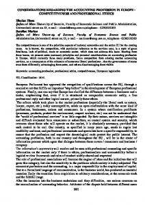
As the SQUID magnetometer destined to biomagnetic measurements has a very low sensitivity threshold, it shows some limitations concerning the immunity with respect to the external magnetic and electromagnetic environment; besides the cautions related to the insurance of an adequate shielding, the electromagnetic emplacement conditions need also to be considered. Besides prospecting, it is also recommended to perform a 24 hours recording of the field variation level, both during the working and the rest days. The geographic coordinates of the laboratory are (Fig.2) [3]: longitude: 47o10’25’’ N latitude: 27o35’19’’E altitude: 240 m. The magnetic field calculated according to the geophysical model [4] has the following components: total component F= 49102.5 nT horizontal component: H= 21294.6 nT; vertical component: Z= 44244.7 nT W-E component: Y= 2094.2 nT S-N component, X= 21191.4 nT declination: D= 5o30’ inclination: I= 64o18’. The magnetic field measured inside the laboratory has the following main components: total component: F= 41.218 nT horizontal component: H= 16.610 nT vertical component: Z= 37.600 nT declination: 14o inclination: 64o4’. The existing differences between the values calculated with the physical model and the measured ones are due to both the geophysical peculiarities at the land level, and the effect of the ferromagnetic masses embodied in the building and the neighboring perimeter which manifest as the existence of a local anomaly. At the same time, measurements of the local magnetic and electromagnetic fields were also performed. The following fields have been explored: local geomagnetic field inside the laboratory; 50 Hz fields radiofrequency and microwave fields; field produced by the human activity along 24 hours.
98
“Mircea cel Batran” Naval Academy Scientific Bulletin, Volume XVI – 2013 – Issue 2 Published by “Mircea cel Batran” Naval Academy Press, Constanta, Romania
Figure 1. Natural and artificial magnetic fields
Figure 2. Laboratory location (Faculty of Medical Bioengineering)
99
“Mircea cel Batran” Naval Academy Scientific Bulletin, Volume XVI – 2013 – Issue 2 Published by “Mircea cel Batran” Naval Academy Press, Constanta, Romania 2. STUDY OF THE ELECTROMAGNETIC ENVIRONMENT The equipment used in this study consisted in spectrum analyzers for high frequency field measurements namely “VHF Analyzer” type HF35 (GHZ Solution) and an EFA 300 (Narda) analyzer; for very low frequency and geomagnetic fields, we used a “3-Axes Fluxgate Magnetometer” (Applied Physics System), a goniometer and an X, Y, Z, t recorder. For geomagnetic field monitoring [5], [6], [7], the measurements were performed during time intervals when the diurnal geomagnetic activity and the magnetic disturbances due to the human activity are minimum (by night). During the magnetic calm intervals, the basic spectrum of the local geomagnetic field has variations of some dozens of gamma, with a periodicity reported to values of the order of hours (about 24, 12, 8 and 6 hours
respectively). These variations depend on the dynamics of the currents from the magnetosphere. Following the measurements performed at two different locations – BIM and a location close to the tramway- it has been noticed that the geomagnetic calm interval can be disturbed by the human activity; in the BIM location one can speak about a geomagnetic calm (Fig. 3), but in the other location the geomagnetic calm period is disturbed by vehicle circulation around the laboratory perimeter (Fig. 4). In both cases, one can notice that during 10 p.m. - 4 a.m. interval, the values of the ambient magnetic field are much smaller, due to the suspension of the human activity during this interval. The recorded magnetograms present the variations of the East-West component, perpendicular to the magnetic meridian. The recorder sensitivity was of 25 nT/cm.
Figure 3. Magnetogram recorded in the laboratory location
Figure 4. Magnetogram recorded near the tramway location measurements were performed was of about 1 m. The start point of the measurements was the most distant point from the wall of laboratory location, along the perimeter in the N-E corner of the building, the measurements direction being the N-S direction. The 3D graphical representation (Fig. 5) of the magnetic field values shows that, as expected, the lowest values, namely 3,800 nT, were in front of the power transformers of 2 x 630 kVA (Fig. 6).
For the low frequency measurements, especially for those at 50 Hz, the EFA 300 analyzer was used, which has its frequency range 5 Hz ÷ 32 kHz, with a resolution of 0.1 Hz at the frequency of 32 kHz. The measurements were performed in a weekend day, with low atmospheric humidity, within the laboratory perimeter with the dimensions of (12 x 30) m. An imaginary network was mapped out on this surface, with mesh size of 0.5 x 0.5m. The height at which the
100
“Mircea cel Batran” Naval Academy Scientific Bulletin, Volume XVI – 2013 – Issue 2 Published by “Mircea cel Batran” Naval Academy Press, Constanta, Romania
Figure 5. The 3D graphical representation of the magnetic field outside the building
Figure 6. Magnetic field distribution within the building perimeter perimeter, before starting the measurements in themselves, an imaginary network was mapped out, with mesh size 0.6 x 0.6 m, at a height of 1 m from the floor. The measurements started in the S-E corner of the room. The magnetic field distribution inside the laboratory, recorded with two identical apparatuses, used by two different operators under the same conditions of space and time (simultaneity) is presented in Figure 7.
The measurements were repeated during a working day, only against the wall with the transformers, in which case the measured values were of about 5,000 nT. The total magnetic field component was measured. In order to complete the magnetic map of the chosen location, the measurements continued with those performed inside the laboratory where the shielded room is located. They were performed several days on end, during both day and night time. As in the case of the external
Figure 7. Distribution of the 50 Hz magnetic field inside the laboratory measurements were continued for 24 hours only in this point (Fig. 8).
A maximum value of about 160 nT corresponding to the zone of low power (20 VA) transformers can be noticed. Given this fact, the
101
“Mircea cel Batran” Naval Academy Scientific Bulletin, Volume XVI – 2013 – Issue 2 Published by “Mircea cel Batran” Naval Academy Press, Constanta, Romania
Figure 8. Representation of 24 hour variation of the magnetic field near the low power transformer The amplitude difference is not representative for the shielded room performances, because both inside and outside the room, the specific noise of the EFA 300 apparatus is superposed on the measured field level.
The point of maximum diminishes by night, considerably increasing then from about 50 nT to about 200 nT during the day, when the laboratory activity begins. Measurements of the time variation of the 50 Hz field were also performed inside the shielded room (Fig. 9).
Figure 9. Representation of 24 hour variation of the shielded room magnetic field 500 MHz; Horn antenna model AT4002A. The results of the measurements within the radiofrequency range (190 ÷ 2700) MHz, inside the shielded room are presented in Figure 10.
For radio frequency and microwave measurements, the following equipment was used: IFR 2398 Spectrum Analyzer, frequency range 9 kHz ÷ 27 GHz, from -105 dBm to +20 dBm; close range field probe, model 7405, ETS, EMECO, frequency range 100 kHz ÷
Figure 10. Electromagnetic field inside the shielded room measured with a HF 35C spectrum analyzer equipped with a periodic log antenna outside the laboratory, within the building external perimeter
Outside the laboratory, within the external building perimeter, Figure 11 presents the electromagnetic field values within the (800 ÷ 2500) MHz frequency range,
102
“Mircea cel Batran” Naval Academy Scientific Bulletin, Volume XVI – 2013 – Issue 2 Published by “Mircea cel Batran” Naval Academy Press, Constanta, Romania
Figure 11. Level curves of the electromagnetic field outside the building The measured levels of the ambient electromagnetic field determined both the choice of the installation emplacement inside the building, and the
optimum solutions for shielding and compensation of these fields [8].
3. COMPATIBILITY ASSURANCE AND INSTALLATION DESCRIPTION Compatibility assurance of the installation involves two frequency range and two very different applications: biomagnetism (from D.C. to 1,000 Hz) and radiometry (microwave). 3.1 Biomagnetometry applications The biomagnetometry installation consists of the following components: parallelepiped shielded room made of nonferromagnetic materials, with the dimensions (2 x 2 x 3) m; triaxial system of Helmholtz coils sized (4 x 4 x 4) m, the shielded room being located inside the volume formed by them; superconducting magnetometer HTS SQUID model 703/53 VA, which includes: SQUID sensor, Dewar vessel, a cryostat and circuits for producing and maintaining the critical temperature, an electrostatic screen; magnetometer type “APS 536 3 Axis Fluxgate Magnetometer” Applied Physics System, for the control of the magnetic field automated compensation and vector monitoring system;
wood bed movable on the horizontal along the Ox, Oy directions, without ferromagnetic insertions or accessories; electronic blocks used to supply the LED lamps and the two dust fans, the camera tubes and the microphones located inside the room, for outside communication; module for the 220V/50 Hz mains supply, which provides the galvanic separation of the inside room plugs from the 220 V mains of the building, and mains electromagnetic compatibility; laboratory and room safety outlet separated from the building mains. 3.1.1. Shielded room Because the costs for the construction of a shielded room made of ferromagnetic materials were very big, we chose as shielding solution to build a shielded room made of non-ferromagnetic material, namely of aluminum, accompanied by a coils system for geomagnetic field compensation. The shielded room consists of a parallelepiped shield sized (3x 2x 2) m, made of 12 mm thick aluminum plates; it is placed on wood scaffolding in the middle of the floor-to-ceiling distance; the scaffolding feet are fixed on rubber structures to attenuate the microvibrations. -
Figure 12. Shielded room
103
“Mircea cel Batran” Naval Academy Scientific Bulletin, Volume XVI – 2013 – Issue 2 Published by “Mircea cel Batran” Naval Academy Press, Constanta, Romania component of the electromagnetic field is of interest. Knowing the field phase inside the shield is important for the utilization of the magnetic field dynamic control, which operates in the negative feedback loop. It has been experimentally found that a parallelepiped shielded room has different damping factors along the three directions (see Figure 13). At the same time, the field phase inside the shielded room changes differently along the three directions, within the volume included between the geometric centre and the room walls. The different values of the shielding coefficients along the three directions are due to the coupling factors between the three pairs of Helmholtz coils and the room walls, different along the three directions [9].
A bed is placed inside the room, made of nonferromagnetic material, which can move horizontally along two directions (X, Y) on two runways of rolled aluminum. The motion is performed by means of two nonferromagnetic cables controlled by two step-by-step motors (along the two moving axes), located at the outside, some meters apart from the shielded room. The displacement is controlled by a computer with dedicated software. Above the bed there is a three channels HTS SQUID magnetometer transducer, by whose means one can measure, depending on configuration, both the biomagnetic field along three orthogonal directions, and the 1st and 2nd order gradients. At low frequencies, the phenomena occur in the magnetic induction zone and, therefore, only the magnetic
Figure 13. Shielding factors of the room along the three directions feedback coefficient can become constant within the entire frequency range and equal to the negative feedback coefficient for external fields. The variation of the magnetic field phase inside the shielded room for the Ox direction, and the representation of the internal residual field phase variation in the room walls planes are presented in Figure 14.
The phase variation at the inside is important because the system that works in the negative feedback loop, having its sensors at the inside, must preserve a phase relationship corresponding to a steady regime. Therefore, a frequency dependent phase-correcting circuit needs to be introduced in the negative feedback loop of the power amplifier that injects compensation currents through the external coils. In this way, the negative
Figure 14. The phase of the alternative magnetic field inside the shielded room configuration, along the three spatial directions, in an orthogonal system, having its Oy axis approximately along the geographic meridian. The dimensions of the three pairs of Helmholtz coils are: coils along the Ox directions: (3050 x 3050) mm; coils along the Oy direction: (3200 x 3200) mm; coils along the Oz direction: (4000 x 4000) mm.
3.1.2. Helmholtz coil system for ambient field control The coil system plays two roles, namely providing for the compensation of the geomagnetic field static component, and of the variable components; these are due to the natural variations of the geomagnetic field and human activity. The control is accomplished by introducing a negative feedback loop which performs the dynamic compensation. The geometric configuration of these coils is as follows: three pairs of square coils, placed in a Helmholtz
104
“Mircea cel Batran” Naval Academy Scientific Bulletin, Volume XVI – 2013 – Issue 2 Published by “Mircea cel Batran” Naval Academy Press, Constanta, Romania the operator to choose, depending on necessities, an analog voltage using a multiturn potentiometer, or a voltage resulting from the digital/analog converter controlled from the keyboard. The option is chosen by means of a switch. The electric currents through the 6 pairs of Helmholtz coils, three for manual compensation and three for automated control, are controlled by means of a voltage-controlled power source of current. The Figure 15 presents the block diagram of the module that contains the three current sources for manual compensation.
The coils for the compensation of the horizontal components (X, Y) are oriented along the N-S (approximately along the magnetic meridian) and E-W directions respectively. The system for manual compensation of the magnetic field static components uses 3 conductively uncoupled identical circuits that control the intensity of the electric current through the high constant windings of the Helmholtz coils. The control is digital and is performed from the keyboard from the panel of the corresponding channel. The voltage for current source control is applied through a switch which permits
Figure 15. Block diagram for vector compensation of the static component volume where the field transducers of the magnetometer are located. In order to have a minimum field near the SQUID transducer, the magnetometer must be placed in its proximity. The field level reached through manual compensation can be, in some situations, around 1 ÷ 2 nT, but this is not a stable state, given the fluctuations and the reduced precision of the analog and digital compensation systems. The residual component still uncompensated by the manual system is taken up and reduced by the negative feedback system.
The automated system which performs the compensation of the alternative and slowly variably components of the geomagnetic field is controlled by a triaxial magnetometer with saturable fluxgate introduced in the magnetic field negative feedback loop. The Figure 16 schematically presents the block diagram of the dynamic compensation system for the three pairs of coils. In principle, the triaxial magnetometer can be located anywhere inside the Helmholtz coils. Depending on its position, the currents through the Helmholtz coils will compensate the magnetic field components from the
105
“Mircea cel Batran” Naval Academy Scientific Bulletin, Volume XVI – 2013 – Issue 2 Published by “Mircea cel Batran” Naval Academy Press, Constanta, Romania
Figure 16. Dynamic compensation of the magnetic field variable components The compensation precision is given by multiturn potentiometer precision, which is 1/1,000, which represents, for the maximum field range, 50 nT. The precision is better for the digital control, namely 5 nT. This can be accomplished under the condition that the ambient field is constant within these limits. The module of dynamic compensation has the following functional characteristics: compensation range: ±5,000 nT supplied current intensity: maximum ±1 A signal delivered by magnetometer: ±10 V (10 mV/100 nT) load: Helmholtz coils for dynamic compensation. The installation performances permitted to record, for the first time in Romania, a biomagnetic signal: the magnetocardiogram of a human subject [10].
This system reduces not only the ambient field disturbances, but also the field fluctuation generated by the manual compensation system. The dynamic compensation system is useful exactly because it is impossible to precisely establish the value of the continuous component through manual compensation. 3.1.3. Characteristics and performances The system permits the manual compensation of the magnetic field by applying through the three pairs of Helmholtz coils, a magnetic field with the maximum induction of ± 50,000 nT. The field polarity is chosen by means of a switch connected to the coils. The main characteristics are: static compensation range: ±50,000 nT maximum delivered current: ±1 A field control modes: analogue and digital current measurement and indications: ±1.0000 A.
Figure 17.a. Unfiltered MCG signal
Figure 17.b. MCG signal after filtering
106
“Mircea cel Batran” Naval Academy Scientific Bulletin, Volume XVI – 2013 – Issue 2 Published by “Mircea cel Batran” Naval Academy Press, Constanta, Romania microwave radiometry, the room has applied on the inside an absorbent structure with pyramidal geometry made of carbon-rich composite material [11], Figure 18.
3.2. Radiometry applications In order to extend the bioelectromagnetism applications into the high frequency range-, i.e. thermography exploration of the living structures using the
A cm 11,4
B cm 8,9
C cm 3,8
D cm 2,5
Figure 18. Dimensions and shape of the absorbent material In order to study the electromagnetic field influence on the organism response by means of its own biomagnetic fields, it is necessary to carry out these researches within an electromagnetic field of minimum intensity. In this connection, the anechoic room provides an adequate medium (Fig. 19).
In this way, the shielded room is converted from a “Faraday cage” into an anechoic room. It is recommended to perform the researches related to microwave thermography within a medium where the electromagnetic field level is as close to the noise level of the field transducer as possible.
Figure 19. Microwave radiometry inside the anechoic room (a) and the shield for temperature calibration (b) within the radiofrequency range. For sources within the date radio traffic range (800 ÷ 2700) MHz whose position is known, the laboratory field level and distribution were measured. The residual fields inside the laboratory and the shielded room are given in Fig. 20
In order to assess the shielded room performances, comparative measurements of the electromagnetic field were carried out within the laboratory perimeter, inside it and inside the shielded room respectively. The measurement results have proved the existence of some sources of radiofrequency disturbances .
Figure 20. Electromagnetic field from laboratory outside the shielded room The microwave radiometry [12] is used to measure the human body temperature with the view of an
early detection of the mammary cancer, in the preclinical phase.
107
“Mircea cel Batran” Naval Academy Scientific Bulletin, Volume XVI – 2013 – Issue 2 Published by “Mircea cel Batran” Naval Academy Press, Constanta, Romania 4. CONCLUSIONS The characterization of the electromagnetic medium and the identification of the magnetic and electromagnetic fields sources were accomplished with a view to find and apply solutions to reduce the ambient field level down to convenient values. The measurements were directed toward the natural geomagnetic field, disturbances due to human activity and to some equipment, as well as toward electromagnetic fields of the (0.8 ÷ 2.7) GHz range. The installation has two specific destinations: biomagnetic field measurements and temperature measurement using microwave radiometric means. Two systems of triaxial coils were used for magnetic field static and dynamic control. Installation permitted to record, for the first time in Romania, the magnetocardiogram of a human subject. Using the microwave radiometry it was possible to obtain, for the first time in Romania, the thermal image of a human subject by measuring the noise temperature. REFERENCES 1. R. M. Gulrajani, Bioelectricity and biomagnetism, John Wiley & Sons, New York, 1998 2. M.C. Rau, Ph.D. Thesis, Researches In Biomagnetic Measurements “Gh. Asachi” Technical Univ of Iasi, Romania 3. *** NOAA's Geophysical Data Center, Available 4. *** Magnetic declination, Available: http://magnetic-declination.com/ 5. M. Rau, O. Baltag, I Rau, S.C. Goiceanu, Study for the location of a bioelectromagnetic research laboratory, Proc. of the 16-th Int. Conf. “Inventica 2012” pp. 370-374, 2012 6. O. Baltag, M. Rau, Bioelectromagnetic researches and special electromagnetic compatibility issues, 8-th International Workshop of Electromagnetic Compatibility CEM 2012, Sibiu, sept. 2012 7. M. Rau, V. David, O. Baltag, Study on the electromagnetic environment in a space destined to bioelectromagnetism researches, EPE Iasi 2012 8. O. Baltag, D. Costandache, M. Rau, Installation for Biomagnetic Researches JBAP, vol. No. 1, pp. 15-21, 2012 9. O. Baltag, D. Costandache, M. Rau, A. Iftemie, I. Rau, Dynamic shielding of the magnetic fields Advances in Electrical and Computer Engineering, vol. 10, pp. 135-140, 2010 10. O. Baltag, D. Costandache, A. Iftemie, M. Rau, I. Rau, S. Ojica, Recording of the first magnetocardiogram in Romania, 12th International Balkan Workshop on Applied Physics, IBWAP 2011, Constanta, Romania, 6-8 July 2011 11. www.eccosorb.com 12. O. Baltag, A. Banarescu, D. Costandache, M. Rau and S. Ojica, Microwaves and Infrared Thermography – Applications in Early Breast Cancer Detection, IFBME Conference MediTech 2009 Cluj-Napoca, Advancements of Medecine and Health Care through Technology, IFMBE Proceedings Vol. 26 pp.195-198, 2009.
108