Typeset with jjap2.cls
Regular Paper
Constrained Parity-Check Code and Post-Processor for Advanced Blue Laser Disk Kui Cai1 ∗ , Kees A. Schouhamer Immink2 † , Jan W. M. Bergmans3 ‡ , and L. P. Shi1 § 1
Data Storage Institute, DSI Building, 5 Engineering Drive 1, Singapore 117608
2
Turing Machines Inc., The Netherlands.
3
Technical University of Eindhoven, The Netherlands.
We propose an advanced detection approach based on capacity approaching constrained parity-check codes and multiple-error-event correction post-processing for high density blue laser disk systems. Simulation results with the blu-ray disc show that an increase of 5GB in capacity can be achieved over the standard system. KEYWORDS: Constrained codes, finite state machine (FSM), parity-check codes, post-processor.
1. Introduction Coding and signal processing have become increasingly important and powerful parts of optical recording systems. The reception techniques for blue laser disk systems (i.e. the blu-ray disc (BD)1) and high-definition digital versatile disc (HD-DVD))2) are significantly different from that used in compact disc (CD) and DVD. For example, the threshold detector is replaced by more powerful Viterbi-like bit detectors, and the minimum runlength constraint3) is reduced from d = 2 to d = 1. Improvements have also been made in pre-processing, which increase the recording capacity of BD from the standard 23.3-25-27 GB to 35 GB on a single layer.4) In this paper, we propose an advanced detector with a novel capacity approaching constrained parity-check (PC) code and a multiple-error-event correction post-processor, for blue laser disk systems with even higher capacity. A block diagram of the d = 1 channel with PC codes and post-processing is shown in Fig. 1. The d = 1 constrained PC encoder adds the d = 1 constraint as well as parity-check constraints on fixed-length segments of user data. Violation of the parity-check constraints in the detected bit sequence enables error detection. For error correction, a post-processor working on channel side information is used. In this way, dominant short error events at the output of the channel detector can be corrected by the PC code with very low redundancy, and the correction capacity loss of the outer error correction code (ECC) is reduced. Therefore, this approach provides an efficient solution to ∗
Email Email ‡ Email § Email †
address: address: address: address:
Cai
[email protected] [email protected] [email protected] Shi
[email protected]
1/15
Jpn. J. Appl. Phys.
Regular Paper
improve the overall performance, with affordable implementation complexity. From Fig. 1, we can see that the design of efficient constrained PC code and the development of simple and effective post-processor are two key issues for the development of PC codes based receivers.5–8) The purpose of PC codes is to detect the presence of errors and provide some localization in error type and position. This is done by imposing specific parity-check constraint on the channel bit stream. Since the modulation constraints should also be simultaneously satisfied, an additional code rate loss will be incurred. Although many attempts have been taken by researchers in recent years to efficiently combine the constrained codes with the PC codes,9–12) the systematic design of constrained PC codes with minimum code rate loss remains an open problem. It is especially difficult to design constrained PC codes that satisfy multiple-bit parity-check constraints for the optical recording systems. In this paper, we propose a general and systematic way for constructing capacity approaching constrained PC codes, which can detect any dominant error events or error event combinations in optical recording systems. As an example, a new 4-bit constrained PC code is designed and applied to BD systems. The optimum detection for a parity-check coded channel is performed using Viterbi based sequence detection on the combined trellis of the channel and PC code.7, 8) But, this may be computational very expensive since the number of trellis states grows exponentially with the length of channel partial response (PR) target and the number of parity-check bits. On the other hand, the parity-check based post-processing schemes have been shown to be simple and efficient soft-decision decoders.5–8, 11) Most of the parity-check based post-processing schemes correct errors by assuming that there is only one error event within one PC codeword.5–8, 11) Obviously, these schemes may make mis-corrections when multiple error events occur within one codeword. This will especially degrade the system’s performance at low signal to noise ratio (SNR) or high recording density. In this paper, we propose a novel post-processing scheme that can correct multiple error events per PC codeword. This paper is organized as follows. In Section 2, we review the discrete-time model of the optical recording channel. A novel technique for designing capacity approaching constrained PC codes is proposed in Section 3. A multiple-error-event correction post-processor is developed in Section 4. Simulation results with the BD system are presented in Section 5. Finally, concluding remarks are given in Section 6. 2. Channel Model The discrete-time model of the optical recording channel with equalization is shown in Fig. 2. Here, {ak }, ak ∈ {−1, 1} denotes the parity-check coded d = 1 non-return-to-zero (NRZ) data sequence, hk and wk denote the Tc -spaced sampled channel symbol response and equalizer, respectively, and {nk } denotes the channel noise which is modelled as AWGN with variance σn2 . In this paper, we assume that the optical read-out is linear and use a generalized 2/15
Jpn. J. Appl. Phys.
Regular Paper
Braat-Hopkins model13, 14) to describe the channel. The Fourier transform of hk is expressed as
H(Ω) =
2RTu sin(π Ω) π2 Ω
q h i Ω | 1 − ( Ω )2 arccos(| RΩ |) − | Ωu RΩu R Ωu for | RΩ Ωu | < 1, Ω for | RΩu | ≥ 1,
0
(1)
where Ω is the frequency normalized by the channel bit rate 1/Tc , and R is the code rate of the d = 1 constrained PC code. The quantity Ωu = fc Tu , where fc is the optical cut-off frequency, is a measure of the recording density. The smaller Ωu is, the higher is the recording density, and vice versa. For an optical recording system using a laser diode with wavelength λ and a lens with numerical aperture NA, the normalized cut-off frequency is given by Ωu =
2NA λ Lu ,
where Lu is the spatial length of one user bit. For the BD systems with λ=405 nm, NA=0.85, rate 2/3 17PP code,1) and at the nominal capacity of 25GB, we get Lu =111.75 nm, and Ωu ≈ 0.47. Similarly, at the capacity of 30GB, we have Lu =93 nm, and Ωu ≈ 0.39. The noise variance σn2 is determined by the user SNR defined as µP 2 ¶ hku σu2 2 user SNR(dB) = 10 log10 , σ = , n σu2 R
(2)
where σu2 is the noise variance in the user bandwidth 1/Tu , and hku is the channel symbol response for R = 1 and Ωu = 0.33.14) The above definitions of channel response and SNR provides a fair basis to compare the performance for different coding schemes and recording densities. In this study, the equalizer taps are tuned to realize a a 7-tap optimized channel PR target gk ,15) and a Viterbi detector (VD) is used as the channel detector. Using the theoretical analysis described in,15) dominant error events at the VD output can be obtained. They turn out to be ±{2}, ±{2, 0, −2}, ±{2, 0, −2, 0, 2}, and ±{2, 0, −2, 0, 2, 0, −2}. 3. Novel Capacity Approaching Constrained Parity-Check (PC) Codes 3.1 General Principle The general principle of the new code design is as follows. The structure of a constrained PC code includes two component codes: the “normal constrained (NC) code” and the ‘parityrelated constrained (PRC) code”. The leading part of a constrained PC code is a group of NC codewords (of i1 bits), while at the end, a PRC codeword (of i2 bits) is appended to impose a specific parity-check constraint over the entire codeword (of i = i1 + i2 bits). This paritycheck constraint corresponds to a predetermined generator matrix (or generator polynomial) of a [j, i] linear binary PC code,16) which is defined to detect any dominant error events or error event combinations of the system. For ease in imposing the modulation constraints, the generator matrix needs to be designed to generate a systematic code. During encoding, the NC codes are first constructed and connected. The parity bits of the sequence of NC codewords (appended with i2 tailing bits of zeros) are then computed. After 3/15
Jpn. J. Appl. Phys.
Regular Paper
that, a specific PRC codeword, which produces the same parity bits when appended with i1 leading bits of zeros, is selected from a candidate codeword set and concatenated directly with the NC codewords, thus forming the combined constrained PC codeword. The parity bits of the combined codeword are thereby set to be zero, since the PC code is systematic and linear over Galois field GF(2). The combined codeword is then transmitted to the channel. Its parity bits need not to be appended since they are pre-determined and known by the receiver. At the detector output, by checking the parity bits reconstructed from the received constrained PC codeword, which are equal to the syndrome of the received codeword (appended with j − i bits of zeros), errors in the received codeword can be detected, which are within the error detection capability of the corresponding PC code. The NC code and the PRC code are finite-state constrained codes designed based on the same FSM. In principle, any efficient FSM can be used in conjunction with the proposed code design approach. For optical recording systems, we choose to use the FSM proposed in,17) since capacity approaching codes can thereby be obtained. This also enables the two component codes to be connected in any order without violating the modulation constraints. As a result, no additional bits are needed for stitching the two component codes together. Furthermore, since the PRC code is also protected by parity-checks, error propagation due to the PRC code is avoided. In addition, by applying the Guided Scrambling (GS)17) scheme to the NC code, whose codewords occupy the major portion of the combined constrained PC code, as shown in,17) satisfactory dc-free performance can be achieved. The rate of the designed constrained PC code is given by R=
M n = Rn − (Rn − Rp ), N N
(3)
where M , N , and n are the length of the segment of user data, the combined constrained PC codeword, and the PRC codeword, respectively, and Rn and Rp are the rates of the NC code and the PRC code, respectively. The choice of N depends on the specific recording system and is a compromise between the code rate loss due to parity-check and the error correction capability of the post-processor. A detailed discussion on the choice of N is given in Section 5.1. Channel coded sequences are generated by a constrained encoder followed by a precoder, i.e. a modulo-2 integration operation. The constrained encoded bits before and after the precoder are referred to as an non-return-to-zero-inverse (NRZI) sequence, and an NRZ sequence, respectively. Most of the prior art schemes design codes in NRZI format.9–12) Using the proposed code design technique, constrained PC codes can be designed either in NRZI format or in NRZ format. On the other hand, we find that for PC codes and post-processing based detection approach, it is preferable to impose the parity-check constraint on the NRZ sequence at the output of the precoder, rather than the NRZI sequence at the input of the precoder. 4/15
Jpn. J. Appl. Phys.
Regular Paper
This is due to the following reasons. In the NRZI case, error detection and post-processing have to be done at the output of the NRZ to NRZI inverse precoder. The process of inverse precoding will cause error propagation and thus increase the length of error events. For example, a single bit error in NRZ format will be converted into a transition shift error of 2 bits in NRZI format, due to inverse precoding. As a result, the number of parity bits required for detecting errors may increase. Furthermore, carrying out post-processing at the output of the detector is simpler and more straightforward than doing it at the output of the inverse precoder. In the following, we present the method for designing codes in NRZ format. 3.2 Encoder Description Fig. 3 is a block schematic for encoding a constrained PC code in NRZ format. As illustrated, a M -bit segment of user data is partitioned into K + 1 data words. The K leading data words are individually encoded into the first component codewords by the NC encoder. The obtained NRZI format codewords are then converted into NRZ format through a precoder. The encoder further includes a parity-check unit, which calculates the parity bits of the sequence of the leading K NRZ NC codewords (appended with i2 tailing bits of zeros), based on an assumed initial NRZ bit. To do this, ‘0’ and ‘1’ are used to denote NRZ bits ‘−1’ and ‘+1’, respectively. The obtained parity bits as well as the last bit of the NRZ sequence are then passed to the PRC encoder, and used to guide encoding the (K + 1)’th data word into the PRC codeword in NRZI format. The PRC codeword needs to be converted into NRZ format before concatenating with the NRZ format NC codewords. During encoding, the next state information is passed from each codeword to the next. It indicates the next state from which to select a codeword for encoding the next data word. Concatenating the NC codewords and the PRC codeword together, results in the combined constrained PC codeword in NRZ format. Finally, we remark that GS needs to be applied to the NC codewords to impose the dc-free constraint. It is not shown in the figure for the sake of simplicity. 3.3 Design of the Parity-related Constrained (PRC) Code In the design of the NC code, we use the FSM proposed in17) to achieve high encoding efficiency. In the design of the PRC code, we propose a novel approach to design sets of codewords with distinct parity bits, based on the same FSM of the NC code. These parity bits correspond to a predetermined generator matrix. Furthermore, they are computed in the NRZ format, rather than in the NRZI format with an assumed initial NRZ bit. The approximate eigenvector equation 3) guides a variety of code constructions, such as the renowned state-splitting method.3) For the design of the PRC code, we propose a set of criteria which are equivalent to the approximate eigenvector equation, taking into account of the parity-check constraint. To design a PRC code with m user data bits and p parity bits, and based on the FSM of 5/15
Jpn. J. Appl. Phys.
Regular Paper
d = 1 codes proposed in,17) we can obtain the following criteria: ξ|C00 | + ξ1 |C01 | ≥ ξ1 2m+p ,
(4)
ξ (|C00 | + |C10 |) + ξ1 (|C01 | + |C11 |) ≥ ξ2m+p ,
(5)
where C00 denotes the set of codewords starting and ending with a ‘0’, C01 denotes the set of codewords starting with a ‘0’ and ending with a ‘1’, etc. Here, |Cab | is the size of the codeword set Cab . The encoder has ξ states, which are divided into two state subsets of a first and second type. The encoder has ξ1 states of the first type and ξ2 = ξ − ξ1 states of the second type. All codewords in states of the first type must start with a ‘0’, while codewords in states of the second type start with either a ‘0’ or a ‘1’. Furthermore, for each set of the codewords that has the same parity bits, the criteria that guide the design of each set of codewords are given by ξ|Cˇ00 | + ξ1 |Cˇ01 | ≥ ξ1 2m ,
(6)
¡ ¢ ¡ ¢ ξ |Cˇ00 | + |Cˇ10 | + ξ1 |Cˇ01 | + |Cˇ11 | ≥ ξ2m ,
(7)
where Cˇ00 denotes the set of codewords with the same parity bits that start and end with a ‘0’, Cˇ01 denotes the set of codewords with the same parity bits that start with a ‘0’ and end with a ‘1’, etc. Further, |Cˇab | is the size of the codeword set Cˇab . In each set of the codewords with the same parity bits, each codeword has an assigned next state. The same codeword that ends with a ‘0’ can be assigned up to ξ different next states in both the first and second state sets, and therefore can be used to map to ξ different user data words. The same codeword that ends with a ‘1’ can only be assigned up to ξ1 next states in the first state set, and therefore can be used to map to ξ1 different user data words. The particular mapping of the codeword to the data word is a matter of design choice, and is not critical to the operation of the system. However, to ensure unique decodability, the sets of codewords that belong to a given state must be disjoint. The rate of the obtained PRC code is given by Rp = m/n.
(8)
The main steps for the design of the PRC code are as follows. (1) For a PRC code with m user data bits and p parity bits, use the criteria described above to determine the codeword length n and the optimum number of encoder states. Note that at this step, the maximum runlength constraint k is temporarily released (e.g. larger than k = 7 for d = 1 codes, and larger than k = 10 for d = 2 codes). (2) Enumerate all the valid d constrained codewords of length n in NRZI format. Based on the given generator matrix, compute the parity bits of each codeword (appended with i1 leading bits of zeros) in NRZ format with an assumed initial NRZ bit. Distribute the codewords into a group of codeword sets according to their NRZ parity bits. A total of 2p
6/15
Jpn. J. Appl. Phys.
Regular Paper
codeword sets are obtained. (3) For each set of NRZI codewords with the same NRZ parity bits, allocate the codewords to various encoder states by following the FSM of.17) Thus results in a set of 2p sub-tables. (4) Concatenate the 2p sub-tables together, and form a code table for encoding/decoding of the PRC code. Compared with the code table of the NC code, the PRC code table is enlarged by a factor of 2p . In each state of the FSM, there is a set of 2p codewords potentially mapped to one user data word. For the two different initial NRZ bits (i.e. ‘+1’ and ‘−1’), we use the same code table to simplify encoding/decoding. However, in the code table, the order of codeword sets with the same parity bits may need to be adjusted according to the different initial NRZ bit. (5) Tighten the k constraint of the designed PRC code by optimizing the code table obtained from Step (4) by deleting codewords that start or end with long runs of ‘0’s, or by increasing the number of states of the FSM. To do decoding, the detected NRZ data sequence is first converted into NRZI format through an inverse precoder, and the resulting NRZI sequence is further decoded. The operation of the PRC decoder is generally the same as that of the NC decoder,17) but with the code tables being different. Both decoders are sliding-block decoders with a look ahead of one codeword. 3.4 A New 4-bit Constrained Parity-Check (PC) Code for Blue Laser Disk Various new constrained PC codes for different optical recording systems can be designed by using the proposed code design method. For example, using the proposed design method, a new (1,18) 4-bit constrained PC code defined by the generator polynomial of g(x) = 1 + x + x4 is designed in NRZ format, which can detect all the dominant error events of the system as illustrated in Section 2. The rate 9/13 (1,18) code with a 5 states (i.e. ξ = 5, ξ1 = 3, ξ2 = 2) FSM proposed in17) is used as the NC code, since its rate is 3.85% higher than that of the rate 2/3 d = 1 codes1, 2) that are used in BD and HD-DVD systems. The PRC code is a rate 7/16 (1,18) code. With respect to the rate 2/3 d = 1 codes, the rate 7/16 code achieves 1.375 channel bits per parity bit. The choice of the length N of the entire constrained PC code will be presented in Section 5.1. 4. Post-processing Schemes 4.1 Analysis of Parity-Check based Post-Processing In parity-check based post-processing, the purpose of PC codes is to detect the presence of errors. The post-processor handles the task of locating the error positions. The inputs of the post processor are the VD output bits ˆ a = [ˆ a1 , a ˆ2 , . . . , a ˆN ]T , the corresponding detector input samples q = [q1 , q2 , . . . , qˆN ]T as well as the parity-check result. The post-processor needs to maximize the probabilities of correct decisions for the transmitted data sequence 7/15
Jpn. J. Appl. Phys.
Regular Paper
a = [a1 , a2 , · · · , aN ]T based on the above input information. This leads to the maximum a posteriori (MAP) based decision rule for post-processing.18) That is, ˆ e
=
arg max p(q | eji , ˆ a)P (eji , ˆ a),
(9)
eji
where eji is an assumed error event (or error event combination) of type j, starting at position i. Define the k’th element of eji as ( ek−i+1 eji,k = 0
for k = i, i + 1, · · · , i + Le − 1
(10)
otherwise,
where e = [e1 , e2 , . . . , eLe ]T is the error event(s) of length Le , occurring at the output of the VD, and i = 1, 2, · · · , N . The syndrome s obtained from parity-check and the d = 1 constraint help to reduce the number of possible candidates for eji . Here, p(q | eji , ˆ a) is the conditional probability density of the Viterbi input samples and Pj , P (eji , ˆ a) is the a priori probability of eji associated with data pattern ˆ a. We remark that the value of P (eji , ˆ a) for given j and ˆ a is a constant for all i. The value of Pj can be computed theoretically.15) For the channel model described in Section 2, the Viterbi input can be expressed as PLg −1 qk = l=0 gl ak−l + vk , where vk is the sum of residual intersymbol interference (ISI) and channel noise, with zero mean and variance σv2 . A good design of the equalizer and channel PR target can make vk almost white. In the post-processor, the re-constructed Viterbi input samples based on an assumed event(s) eji are given by Lg −1 j q˜i,k
X
=
gl (ˆ ak−l + eji,k−l ).
(11)
l=0
Assuming vk is white and Gaussian, we may rewrite (9) as (N ) t X j 2 2 ˆ = arg min (qk − q˜i,k ) − 2σv ln(Pj ) , e eji
(12)
k=1
with Nt = N + Le + Lg − 2. Simplification can be made on (12), by dropping off the term 2σv2 ln(Pj ). This results in the maximum likelihood (ML) based post-processor. Our study shows that the performance gap between MAP and ML post-processors is negligible. However, the computation complexity of the ML post-processor is still high, since for each assumed error event (s) of type j, and with P t j 2 every possible starting position i, the squared Euclidean distance N ˜i,k ) needs to k=1 (qk − q be computed to locate the error(s). The ML post-processor can be further simplified by rewriting the term That is, Nt X j 2 (qk − q˜i,k ) k=1
8/15
PNt
k=1 (qk
j 2 − q˜i,k ) .
Jpn. J. Appl. Phys.
Regular Paper Nt X
=
k=1
k=1
+
X
2 ³ ´ gl ek−l − eji,k−l + vk
l=0
Nt X
=
Lg −1
2
Lg −1
X
gl ek−l + 2
l=0
Nt X
vk2 − 2
Nt X
PNt
k=1
X
l=0
X
gl ek−l Nt X
l=0
gl ek−l
gm eji,k−m
, 2
2
Lg −1
k=1
´2
m=0
gl eji,k−l vk +
³P Lg −1
gl ek−l vk
Lg −1
l=0
k=1
g −1 Nt LX X
X
Lg −1
Lg −1
k=1 l=0
We note that the terms
k=1
k=1
−2
Nt X
X
j . gl ei,k−l
(13)
l=0
PNt ³PLg −1 k=1
l=0
´ P t 2 gl ek−l vk and N k=1 vk in
(13) are independent of eji . Therefore, these terms can be dropped off and (12) is therefore simplified to ˆ e
=
arg max
where eq,k = qk − qˆk , with qˆk =
eji
Nt X
Lg −1
eq,k
X l=0
k=1
gl eji,k−l − ηj
,
(14)
PLg −1
gl a ˆk−l . Here, ηj is an offset value associated with each P t ³PLg −1 j ´2 type of the error event(s), and ηj is given by ηj = 12 N k=1 l=0 gl ei,k−l . l=0
From (14), we see that the ML post-processor can be implemented by passing the error signal eq,k through a bank of filters which are matched to the assumed error event(s) and normalizing the matched-filter outputs by subtracting a set of offsets associated with these error events. The matched-filter for a given error event(s) is the time-reversed version of the convolution between the error event(s) and the channel target response gi . The above deduced matched-filters based implementation of the ML post-processor is preferred in practice, due to its simplicity. 4.2 Multiple-Error-Event Correction Post-Processor Most of the parity-check based post-processor schemes can only correct single error event within one PC codeword. Thus, in the post-processor, filters that are matched to the dominant error events of the system are used, assuming that only one dominant error event is present in a detected codeword [3,4]. In this Section, we propose a multiple-error-event correction post-processing scheme. Multiple error events occur within one PC codeword are mainly combinations of various (single) dominant error events of the system. According to (14), the straightforward way to do multiple-error-event correction is to use a bank of filters that are matched to the dominant error events as well as their various combinations. However, this is computationally prohibitive, since even for a limited number of dominant error events, there may be numerous combinations 9/15
Jpn. J. Appl. Phys.
Regular Paper
of these events, corresponding to all possible starting positions of the events. Here, we propose a low-complexity multiple-error-event correction post-processing scheme. The key idea is to first use matched-filtering to obtain the possible types and locations of the single error events, and then through computing the squared Euclidean distance of each possible error event or error event combination to determine the most-likely event(s). Fig. 4 shows the block diagram of the parity-check based multiple-error-event correction post-processor. The proposed post-processing scheme is summarized as follows. (1) In the post-processor, we use a bank of filters that are matched to the dominant error events of the system. For each of the matched-filter, the output samples are sorted in descending order of magnitude as candidate outputs. Several largest samples that satisfy the d = 1 constraint are selected to indicate the candidate error events. We restore the corresponding error types and locations. (2) From the candidate error events obtained from Step (1), select single error events as well as various combinations of multiple error events that produce the same syndrome as the parity-check result. Furthermore, each pair of error events is separated by an interval that is larger than the error-free interval, which is the effective length of the channel memory. Several sets of candidate error events can be obtained, e.g. candidate event set 1 contains the single error events, candidate event set 2 contains various combinations of double error events, etc. P t j 2 (3) Compute N ˜i,k ) , the squared Euclidean distance between the detector input k=1 (qk − q samples and their re-constructed versions based on each error event or error event combination in the candidate event sets. The error event(s) with the minimum distance is determined as the most likely event(s). Since the number of candidate error events obtained from Step (2) is quite limited after the first round screening done by the matched-filters in Step (1), the complexity for correcting multiple error events is minimized. The computation complexity of the proposed post-processing scheme can be adjusted according to performance/complexity tradeoffs. In this work, we find that the double-errorevent correction post-processor gives sufficiently good performance for the system under study, since the probability of the occurrence of error events larger than two is trivial. 5. Simulation Results and Discussion In this section, we first discuss the choice of the length of constrained PC codes. We then present simulation results of the proposed new code and post-processing scheme. The BD system is used in simulations. Similar performance can also be expected from HD-DVD systems. 5.1 Choice of the Length of Constrained PC Codes For a given PC code, the choice of a suitable codeword length is a compromise between rate loss and error correction capability. This can be seen as follows. 10/15
Jpn. J. Appl. Phys.
Regular Paper
(1) As described in Section 4, the post-processor assumes that only a few (e.g. single or double) error events are present in a codeword. Obviously, the shorter the codeword length N is, the more likely it is that this requirement is satisfied.
(2) On the other hand, according to (3), decreasing the codeword length will increase the code rate loss. The resulting increase in noise bandwidth and channel density lead to reduced SNR and poor performance.
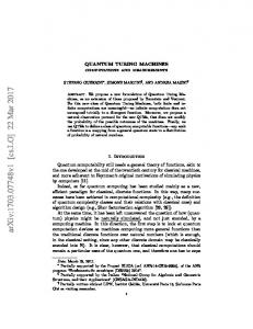
To study the effect of code rate loss stated in Item 2, we compare the bit error rate (BER) performance at VD output of the rate 9/13 (1,18) code with that of PC codes with different codeword lengths (per parity bit). All the BERs can be computed theoretically according to.15) The result shows that the performance loss resulting from rate loss due to the use of PC codes decreases with increase in codeword length. When the codeword length per parity bit is 200, the loss becomes very small. Hence, we conclude that there is no advantage in choosing the codeword lengths (per parity bit) exceeding 200, since this will only increase the probability of multiple error events to occur within one codeword. To study the effect of codeword length on the overall performance, we show in Fig. 5 the BER performance at the post-processor output, as a function of codeword length N . We us the new 4-bit PC code with a double error-event-correction post-processor as an example. In the simulations of Fig. 5, for the sake of simplicity, we do not construct explicit constrained PC encoders with different codeword lengths. Instead, we model the PC codes by assuming that the parity bits for each codeword are known at the receiver. This is done by generating the syndrome for each codeword in a “data-aided” mode. Ideally, for a given density, the optimum codeword length should be a function of SNR. At low SNR, the codeword length should be shorter to ensure that only a few (e.g. single or double) error events are present in a codeword. At high SNR, the codeword length can be larger. However, from Fig. 5, we find that for each SNR, the minimum BER is obtained over a certain range of codeword length. These ranges of codeword length for different SNRs have an overlapping region, which is approximately 400 to 800 bits (i.e. 100 to 200 bits per parity bit). This also agrees with the theoretical analysis on the code rate loss described above. Therefore, at a given density, instead of varying the codeword length for each SNR, we can simply take a fixed codeword length from the overlapping region. Since a shorter codeword length will simplify the complexity of the post-processor, the length of the new 4-bit PC code is chosen to be N = 406. The overall code rate, according to (3), is thus R = 277/406 = 0.6823. Note that the capacity of d = 1 constrained PC codes is given by Rcap = R1,∞ − p/N , where R1,∞ = 0.6942 is the capacity of d = 1 codes.3) Therefore, the rate of the new 4-bit PC code is only 0.3% below the capacity. 11/15
Jpn. J. Appl. Phys.
Regular Paper
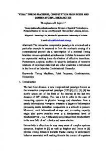
5.2 Bit error rate (BER) Performance Fig. 6 illustrates the BER comparison of the BD system with the standard 17PP code and with the new constrained PC code and post-processing scheme. At the capacity of 30 GB, Curves 1 and 2 indicate the performance of 17PP code and the rate 9/13 code, without parity-check and post-processing, respectively. Curves 3 and 4 show the performance of the new 4-bit PC code in conjunction with a single-error-event correction post-processor and a double-error-event correction post-processor, respectively. The performance bound corresponding to the case when all single and double dominant error events with one PC codeword are removed can be obtained by simulations, and is illustrated by Curve 5. Finally, the BER performance of 17PP code without parity, at the standard capacity of 25 GB, is plotted in Curve 6 as a reference. In the post-processor, four filters matched to the events ±{2}, ±{2, 0, −2}, ±{2, 0, −2, 0, 2}, and ±{2, 0, −2, 0, 2, 0, −2} are used for the new 4-bit PC code. Observe that at the capacity of 30 GB, compared with the performance of the system with 17PP code and without parity, the rate 9/13 code without parity brings a performance gain of 0.8 dB at BER = 10−5 , due to its 3.85% higher code rate. The new constrained PC code with a double-error-event correction post-processor outperforms that with a single-error-event correction post-processor, and achieves an overall performance gain of 1.7 dB. Note that the performance gain is larger at low SNR than that at high SNR, since the probability of the occurrence of double error events is higher at low SNR. Note also that the performance of the double-error-event correction post-processor is very close to the performance bound with both single and double dominant error events removed. This demonstrates the efficiency of the proposed multiple-error-event correction post-processing scheme. It is further observed that over a wide range of SNRs, the performance of the new code in conjunction with a doubleerror-event correction post-processor at capacity 30 GB, approaches that of 17PP code at capacity 25 GB. This shows that compared to the standard BD, an increase of 5 GB in capacity is achieved using the proposed new code and post-processor. Moreover, an approach of the kind proposed in this paper, when combined with advanced pre-processing schemes such as that in,4) has the potential to further increase the capacity of BD. 6. Conclusions In this paper, an advanced detection based on novel constrained PC codes and postprocessing has been proposed for high density blue laser disk systems. The proposed code design technique is general and systematic, using which capacity approaching constrained PC codes can be designed to detect dominant error events and error event combinations of the system. The new post-processing scheme can effectively correct multiple error events within one PC codeword. Computer simulations with BD show that the proposed new code and post-processing scheme have the potential to increase the capacity by 5 GB over the standard system. The implementation complexity of the proposed receiver is quite limited. 12/15
Jpn. J. Appl. Phys.
Regular Paper
Generalization of this scheme to HD-DVD is also straightforward. Acknowledgment Authors would like to thank Dr. George Mathew of National University of Singapore and Dr. Alexander Padiy of Philips Research Eindhoven, The Netherlands, for their valuable insights to this paper.
13/15
Jpn. J. Appl. Phys.
Regular Paper
References 1) T. Narahara, S. Kobayashi, Y. Shimpuku, G. van den Enden, J. Kahlman, M. van Dijk and R. van Woudenberg: Jpn. J. Appl. Phys. 39 (2000) 912. 2) K. Kayanuma, C. Nota and T. Iwanaga: Tech. Dig. Int. Symp. Optcal Data storage (2003) 160. 3) K. A. S. Immink: Codes for mass data storage systems (Shannon Foundation Publishers, 1999). 4) A. Padiy, B. Yin, C. Verschuren, R. Vlutters, T. Jansen and J. Lee: Tech. Dig. Int. Symp. Optcal Data storage (2004) 34. 5) T. Conway: IEEE Trans. Magn. 34 (1998) 2382. 6) W. Feng, A. Vityaev, G. Burd, and N. Nazari: Proc. IEEE Intl. Conf. Global Telecommun. (GLOBECOM), San Francisco, USA, 2000, p. 1877. 7) R.D. Cideciyan, J.D. Coker, E. Eleftheriou and R.L. Galbraith: IEEE Trans. Magn. 37 (2001) 714. 8) Z.A. Keirn, V.Y. Krachkovsky, E.F. Haratsch and H. Burger: IEEE Trans. Magn. 40 (2004) 225. 9) P. Perry, M. C. Lin and Z. Zhang: IEEE Trans. IT. 44 (1998) 1588. 10) S. Gopalaswamy and J.W.M. Bergmans: Proc. IEEE Intl. Conf. Commun. (ICC), New Orleans, USA, 2000, p. 89. 11) W.M.J. Coene, H. Pozidis and J.W.M. Bergmans: Proc. IEEE Intl. Conf. Global Telecommun. (GLOBECOM), San Antonio, USA, 2001, p. 2982. 12) R.D. Cideciyan and E. Eleftheriou: Proc. IEEE Intl. Conf. Commun. (ICC), Paris, France, 2004, p. 635. 13) G. Bouwhuis, J. Braat, A. Huijser, J. Pasman, G. van Rosmalen and K.A.S. Immink: Principles of Optical Disc Systems (Adam Hilger Ltd, 1985), Chap. 2. 14) K. Cai, G. Mathew, J.W.M. Bergmans and Z. Qin: Proc. IEEE Intl. Conf. Consumer Electronics (ICCE), Los Angeles, USA, 2003, p. 324. 15) K. Cai, V.Y. Krachkovsky and J.W.M. Bergmans: Proc. IEEE Intl. Conf. Commun. (ICC), Alaska, USA, 2003, p. 2914. 16) S. Lin and D.J.Costello: Error Control Coding Fundamentals and Applications (PrenticeHall Inc., 1983), Chap. 4. 17) K. A. S. Immink, J. Y. Kim and S. W. Suh: IEEE Trans. Commun. 51 (2003) 326. 18) M.R. Elidrissi and G. Mathew: IEEE Intl. Conf. Commun. Systems, (ICCS), Singapore, 2004. 14/15
Jpn. J. Appl. Phys.
Regular Paper
List of Figures 1) Fig. 1.
Block diagram of d = 1 channel with parity-check (PC) code and postprocessing.
2) Fig. 2.
Discrete-time model of optical recording channel with AWGN and equalization.
3) Fig. 3.
Block schematic for encoding a constrained parity-check (PC) code in NRZ format.
4) Fig. 4.
Block schematic of the parity-check based multiple-error-event correction post-processor.
5) Fig. 5.
BER performance at the post-processor output, as a function of codeword length N . The ‘user SNR’ for each plot is shown in the brackets. Ωu = 0.39, Cap = 30GB.
6) Fig. 6.
BER comparison with the BD system.
15/15
Jpn. J. Appl. Phys.
user data
d=1 constrained parity-check encoder
Regular Paper
recovered data PR channel
Viterbi detector
parity check
postprocessor
constrained decoder
Fig. 1. *Authors: Kui Cai, Kees A. Schouhamer Immink, Jan W. M. Bergmans, and L. P. Shi
16/15
Jpn. J. Appl. Phys.
Regular Paper
nk
ak
rk
hk
wk
qk
gk
Fig. 2. *Authors: Kui Cai, Kees A. Schouhamer Immink, Jan W. M. Bergmans, and L. P. Shi
17/15
Jpn. J. Appl. Phys.
Regular Paper
M - bit user data segment data word 1
... ...
data word 2
data word K
data word K+1
Normal Constrained Encoder next state
next state initial NRZ bit
Parity-related Constrained Encoder
Precoder last NRZ bit ParityCheck Unit
...
next state Precoder
last NRZ bit codeword 1
codeword 2
...
codeword K
codeword K+1
N - bit constrained parity-check codeword (NRZ)
Fig. 3. *Authors: Kui Cai, Kees A. Schouhamer Immink, Jan W. M. Bergmans, and L. P. Shi
18/15
Jpn. J. Appl. Phys.
detector input detector
Regular Paper
aˆ k
paritycheck
aˆ k
d=1 check
error correction
recovered data
d=1 check results
syndrome
η1
post-processing enable qk
gi
mf1 qˆ k
eq,k
mf2
...
candidate event set 1
η2 candidate event set 2
ηj
mfj
...
determine most-likely error (s)
candidate event set L
matched-filters bank
Fig. 4. *Authors: Kui Cai, Kees A. Schouhamer Immink, Jan W. M. Bergmans, and L. P. Shi
19/15
Jpn. J. Appl. Phys.
Regular Paper
−2 1 2 3 4 5 6
−2.5
With 9/13 code + 7/16 code (13 dB) With 9/13 code, w/o parity (13 dB) With 9/13 code + 7/16 code (14 dB) With 9/13 code, w/o parity (14 dB) With 9/13 code + 7/16 code (15 dB) With 9/13 code, w/o parity (15 dB)
log10(BER)
−3
−3.5
−4
−4.5
−5
0
500
1000
1500 2000 codeword length N
2500
3000
3500
Fig. 5. *Authors: Kui Cai, Kees A. Schouhamer Immink, Jan W. M. Bergmans, and L. P. Shi
20/15
Jpn. J. Appl. Phys.
Regular Paper
−2.5 1 With 17 PP code, w/o parity, Cap=30GB 2 With 9/13 code, w/o parity, Cap=30GB 3 With 9/13 code + 7/16 code (N=406) and single−event−correction post−processor, Cap=30GB 4 With 9/13 code + 7/16 code (N=406) and double−event−correction post−processor, Cap=30GB 5 Bound (with single and double error events removed), Cap=30GB 6 With 17 PP code, w/o parity, Cap=25GB
−3
log10(BER)
−3.5
−4
−4.5
−5 13
13.5
14
14.5
15 user−snr in dB
15.5
16
16.5
17
Fig. 6. *Authors: Kui Cai, Kees A. Schouhamer Immink, Jan W. M. Bergmans, and L. P. Shi
21/15