designers and platform designers have to cooperate in order to assess whether an application could be supported by the avionics platform. As the design is.
Constraint-based Design of Avionics Platform – Preliminary Design Exploration P. Bieber3, J.P Bodeveix2, C. Castel3, D. Doose3, M.Filali2, F. Minot1, C. Pralet3 1: AIRBUS, Toulouse, France 2: IRIT, Toulouse, France 3: ONERA, Toulouse, France
Abstract: The PAM project has developed techniques and tools based on constraint solving to assist the avionics platform design team to select the adequate number of resources, the topology of resource interconnection and the safe allocation of resources to functions and data-flows of the supported applications. We explain how avionics platforms and supported functions are modelled and what constraints are taken into account by the PAM approach. The approach is illustrated by a fire detection system case-study. Keywords: Integrated Modular Avionics, Safety, Constraint Solving 1. Preliminary Design Exploration In modern aircrafts, a global avionics platform made of interconnected shareable computing and communication resources is used to support both safety critical applications such as flight control and non-safety critical application such as flight operation assistance systems. The platform design team is in charge of selecting the adequate number of resources, the topology of resource interconnection and the safe allocation of resources to functions and data-flows of the supported applications. System design teams are in charge of the definition of the applications to be supported by the platform. They define the architecture of the applications in terms of functions and data flow exchanged between functions. They also define the level of redundancy and segregation between the various functions and data flows. But they are not responsible for the design of the supporting platform. So, at early stages of the Aircraft design, system designers and platform designers have to cooperate in order to assess whether an application could be supported by the avionics platform. As the design is not frozen, it is important that system and platform designers can easily explore a large number of potential solutions in order to help them find the best way to support the applications.
PA
The PAM (“Platform Architecture Management”) project aims at providing new methods and tools to support the design of avionics platform. The approach is based on models of system functional architecture, avionics platform architecture and constraints on the allocation of the application on the resources of the platform. These models are shared by system designers and platform designers. An important part of the PAM project, not covered by this paper, is the design of a tool that can be used by the design teams to build these models. In this paper we focus on a plug-in to the PAM tool that automates the exploration of platform designs. This tool is based on constraint solving techniques. In the following of this paper we first detail how platform and supported applications are modelled. We introduce a hypothetical Fire Detection System (FDS) as an example that illustrates the notions related with these models. Then we detail the constraints taken into account and we explain how they are formalised. We also describe the tool that supports the proposed method and, finally, we discuss the results we have obtained on the FDS case-study.
2. Application and Platform Models The four models used to support trade-off analysis are: • a description of the application in terms of functions and exchanged data flows, • a description of the platform architecture in terms of interconnected computing and communication resources, • a set of constraints, called allocation directives, derived from safety, operational reliability and functional requirements, • allocations that relate each function and data flow with the supporting resources in the platform. An Ecore data model was created for all these categories of data with the TOPCASED model editor
[1]. XML formats were derived from these models in order to import data from the tool being developed by AIRBUS. But we think that the model and related formats should also be compatible with notations devoted to the description of software architectures such as AADL [2]. In the following of this section, the models are illustrated with a hypothetical Fire Detection System (FDS). Its goal is to manage fire detection sensors that are located in four zones of the aircraft: Engine 1 (E1) on the left wing, Engine 2 (E2) on the right wing, Auxiliary Power Unit (APU) at the rear of the aircraft and Main Landing Gear Bay (MLGB) between the wings at the middle of the aircraft. The FDS computes and sends a Fire Alarm to the Pilot Displays located in the cockpit. 2.1. Functional Architecture Model The functional architecture connects computation activities called functions (denoted by rectangles) with communication activities called data flows (denoted by hexagons).
Figure 2 : FDS – Occurrence Level 2.2. Platform Architecture Model The platform architecture connects together computing equipments such as CPIOM and Sensors denoted by rectangles and communication equipments as Remote Data Concentrator (RDC) and AFDX switches denoted by hexagons. Figure 3. FDS platform – Occurrence level.
The master level description groups together similar functions and data flows: the FireSensor function produces data FireSensorData that is sent to a function FireManagement. This function computes FireAlarm that is sent to the function FireAlarmDispay.
Figure 1. FDS – Master level The occurrence level description is derived from the master level by drawing all the occurrences of the master functions and data flows. There are 8 occurrences, 2 per zones, of FireSensor, FireSensorData and FireManagement. The names of occurrences indicate the zone (E1, E2, APU or MLGB) and the group of the sensor (LA or LB).There are 2 occurrences of FireAlarmDisplay, one for the pilot and the other one for the first officer. There are 16 occurrences of data flow FireAlarm as it is computed by 8 occurrences of FireManagement and sent to 2 occurrences of FireAlarmDisplay (FDS_DU_L and FDS_DU_R).
The FDS platform is made of 8 sensors (SensorNi, i:1..8), and eight RDC that collect the values produced by the sensors and send them via a field bus to one of the 4 CPIOM computers. The CPIOM computers send their data to the 2 Display Units (DU_L and DU_R) via the AFDX network. The AFDX network is made of 5 switches (AFDX_SW1, AFDX_SW2, AFDX_SW3, AFDX_SW4 and AFDX_SWi). The data model associate several attributes with platform equipments such as the side (either side 1 or side 2) or the zone where the equipment is located in the aircraft, the electrical source (either DC1, DC2 or DCEss) of the equipment, the mass of the equipment, the volume needed to install the equipment, the type of media (either analogue, field bus, Arinc 429 or AFDX) if it is a communication equipment, the computation or communication capacity of the equipment, …
Equipments that appear in blue in figure 3 are powered by DC1 and equipments in violet are powered by DC2. CPIOM1, CPIOM2, AFDX_SW1 and AFDX_SW3 are located on side 1 whereas CPIOM3, CPIOM4, AFDX_SW2 and AFDX_SW4 are located on side 2.
2.2. Directive Model Directives are provided by the user to guide the allocation search. Directives are derived from the requirements that the application has to enforce. In the current version of the approach, the directives that we consider are mainly derived from Safety or Operational Reliability requirements such as “Total loss of fire detection is classified Hazardous. No single failure shall lead to this situation. The failure rate shall be less than 1e-7 per flight hour”, “The failure of one FDS equipment shall not lead to flight cancel or delay”. To decide whether a design enforces its Safety requirements system designers apply safety assessment techniques such as the production of fault trees in order to generate safety results (list of failure scenarios, probabilities, …). This decision is often based on the assumption that some group of functions or data flows should fail independently. From these assumptions, System Designers derive a set of allocation directives such segregations or colocations. In [3] we presented a technique that automatically extracts segregation directives from a set of minimal scenarios generated by safety assessment tools. Segregation of a group of functions or data flows means that this group should not be supported by group of equipments with a common point of failure, such if this failure occurs then all supported functions and data flows would also fail. We consider that equipments sharing the same source of electrical power, being located in the same zone or the same side have a common point of failure. Co-location is the dual notion of segregation, i.e. colocation of a group of functions means that this group should be supported by a group of equipments with a common group of failures. In the following we use notation seg_T(f1,f2) (resp. coloc_T(f1,f2)) to denote a segregation (resp. colocation) directive with respect to common point of failure T for functions or data flows f1 and f2. 2.3. Allocation Model An allocation associates a computation equipment to each function and a sequence of communication equipments to each data flow. In most cases, an allocation is the result provided to the user by the method and tool described in this paper. But a partial
allocation may also be provided by the user to guide the allocation search. A total allocation might also be provided by the user, in this case the tool would just check that the allocation is consistent with the constraints derived from the directives. The allocation table given in table 1 describes how the previous platform architecture could support the FDS system. All occurrences of FireManagement are supported by CPIOM1. Each occurrence of FireSensor and FireSensorData are supported by an occurrence of sensor and RDC. Table 1. Allocation table Resources
Functions and data flows
CPIOM1
FMj
SensorNi
FSj
i:1..8
j: E1LA, E2LB, APULA, APULB, E2LA, E2LB, MLGBLA, MLGBLB
RDCi
FSj
i : 1..8
j: E1LA, E2LB, APULA, APULB, E2LA, E2LB, MLGBLA, MLGBLB
3. Formalization of Allocation Constraints Let Function be the set of functions and Data the set of data flows that appear in the functional description, we use two constant functions to formalize the functional description: orig: Data Æ Function associates a data flow with its origin Function and dest : Data Æ Function associates a data flow with its destination Function. Let Cpu and Bus be the set of, respectively, computing and communication resources that appear in the platform description. We note Res = Cpu U Bus the set of all platform resources. Path is the set of all finite paths in the graph of resources, a path is a sequence r1; …; rn such that resource ri is connected to ri+1 in the platform architecture. The length of a path is the number of connected resources. The set of paths of length 1 is equal to Res. The main variable used to formalize allocation constraints is allo: (Function U Data) Æ Path , allo(x) is equal to y whenever x is allocated on resource y. We first explain two allocation constraints that are applicable to any system.
Unique Allocation: Any function (resp. data flow) has to be allocated to one and only one computation resource (resp. communication path). forall t:Function, exists ! c:Cpu, allo(t)=c forall d:Data, exists ! b:Path, allo(d) = b
(.lpformat)
Functional View
Allocation Constraint Generator
Allocation Directives
Compatible connections: If a data flow d is allocated on a path then its origin function should be allocated to the first resource in this path and the destination function should allocated the last resource in this path. forall d: Data, allo(orig(d))= first(allo(d)) and allo(dest(d))= last(allo(d)) The system designers use the following families of allocation directives to constrain the possible allocations. Segregation: Segregated Functions or data flows shall not be allocated to paths with common points of failure of type T. Where T is an attribute associated with equipments in the data model such as equipment name, side, power source,... forall t1,t2: seg_T, not( common_T(allo(t1), allo(t2))) where common_T(p1,p2) = exists r1: p1, r2: p2, T(r1)=T(r2) Co-location : Co-located Functions or data flows shall be allocated on paths that share a common point of failure of type T. forall t1,t2: coloc_T, common_T(allo(t1), allo(t2)) Allocation : All Functions and data flows in F shall be allocated to a Path in R. forall t: F , exists r:R, allo(t)= r Exclusion: All Functions and dataflows in F shall not be allocated to a Path in R. forall t: F , forall r:R, not (allo(t)= r) We use auxiliary variable uscnx: Res*Res Æ {0,1} that is equal to 1 whenever the connection between two resources is used. uscnx is an auxiliary variable because it is defined in terms of the allo variable, it does not constrain the allocation of resources. But it provides a very interesting indication of what connections could be removed in the platform architecture without problems. This variable can be used to provide a quality measure on allocation solutions and to guide the search of good solutions. For instance, we use as a search criterion the minimisation of the number of used connections: Σb:Path,c:Cpu length(b)*(uscnx(b,c) + uscnx(c,b)) as this should help to find architectures with the smaller number of useful communication and computing resources.
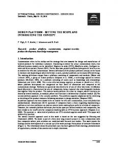
4. Tool support
Architectural View
Allocation Viewer
Constraints
Constraint Solver (ILOGSolver, LPSolve, Satzoo,…)
Allocations
Figure 4 : Tool support for Allocation search and visualisation The three inputs of the allocation search and visualisation tool are: functional architecture and platform architecture descriptions, and a set of allocation directives (segregation, co-location, allocation and exclusion) in the XML format defined. The Allocation Constraint Generator reads the inputs and use them to generate a set of constraints as well as an optimisation criteria. The resulting file is sent to a Constraint Solver that tries to solve the constraints and find an allocation. The Allocation viewer function takes as input the allocation and shows graphically its effect on the function and architecture descriptions. The allocation constraint generator produces constraints compatible with the considered solver. It does not produce constraints as described in the previous section because they do not reflect the constraints that are used by the different tools that we have considered. Minisat [4] solves Boolean logic equations, Satzoo solves {0,1} linear constraints. ILOG Solver solves more general constraints written in OPL language The allocation constraint generator analyses the inputs in order to produce constraints that will be solved more efficiently. For instance, it computes the set of allowed path in the platform architecture instead of adding constraints on allowed paths such as a path shall cross from side 1 to side 2 at most once. It is also possible to pre-compute paths with common points of failure with respect to the various attributes considered. We have developed an experimental Graphical User Interface that has two main windows: one for viewing the platform and the other for viewing the functional description. When the user launches the allocation search, a pop-up window lets the user select the allocation directive and search criterion to be used. If no solution is found then all the functions and data flows of the functional view are coloured in Grey. Otherwise, the result of the optimisation criteria is displayed. Functions and data-flows are coloured
with the colour of the resource that was allocated to them. For instance, the two following picture show an allocation. We can quickly see that all FireSensorData occurrences related with group A (resp. group B) are supported by RDC that are powered by DC1 (resp. DC2) because they are coloured in Blue or Dark Grey (resp. Purple or Light Grey). To investigate allocations in more details, the user can point with the mouse on a resource of the architecture and this highlights the function or data flow that was allocated to it. In the following picture, by clicking on CPIOM1 in the platform view the user highlights functions FME1LA and FMAPULA. Finally, unused connections and resources of the architecture are coloured in Grey. For instance, in the next picture, RDC are connected to only one CPIOM and the ADCN connections and equipments are not used.
Figure 5 : Visualisation of an allocation – Functional view
resources and we consider that SensorN1, SensorN2 are in zone E1, Sensor N3, SensorN4 are in zone APU, SensorN5, SensorN6 are in zone E2 and SensorN7, SensorN8 are in zone MLGB: allocation({FSE1LA,FSE1LB},{SensorN1,SensorN2}) allocation({FSAPULA,FSAPULB},{SensorN3,Sensor N4}) allocation({FSE2LA,FSE2LB},{SensorN5,SensorN6}) allocation({FSMLGBLA,FSMLGBLB},{SensorN7,Sen sorN8}) Similarly we force the allocation of occurrences of FireManagement on CPIOM, we consider that zone E1 is on side1 and E2 is on side 2. We also suppose that CPIOM1 and CPIOM2 are on side 1 and CPIOM3 and 4 are on side 2: allocation({FME1LA, FME1LB }, {CPIOM1,CPIOM2}) allocation({FME2LA, FME2LB}, {CPIOM3,CPIOM4}) To enforce safety requirements, in each zone there shall be segregation of occurrences of FireSensor and FireManagement for group A and group B. Actually it is sufficient to segregate occurrences of FireManagement function: seg_name(FME1LA,FME1LB) seg_name(FME2LA, FME2LB) seg_name(FMAPULA,FMAPULB) seg_name(FMMLGBLA, FMMLGBLB) With this first set of constraints we obtained 256 solutions with 16 used connections. This included the solution described in figures 5 and 6 that was proposed by System Architects. But we also found other topologies for the connection between the RDC and the CPIOM such as the one presented in the following picture where RDC7 is connected to CPIOM1 and RDC4 is connected to CPIOM4.
Figure 6 : Visualisation of an allocation Platform view 5. Case-study results 5.1. FireSensor allocation study We studied the allocation of platform resources to the FDS system in two steps. We first looked at the FireSensor occurrences. So we used a restricted view of the architecture, that is described in Figure 5, where the AFDX switches and the display units are hidden. Allocation directives are used to force the allocation of occurrences of FireSensor function on Sensor
Figure 7. A different allocation choice But if we consider that APU is on side 1 and MLGB is on side 2 and we place FMAPULA and FMAPULB on CPIOM1 or CPIOM3 and we place FMMLGBLA and FMMLGBLB on CPIOM2 or CPIOM4 then the only solution found is similar to what was proposed by the System Architects. 5.2. FireAlarm allocation study
After placing FireSensor occurrences on the platform we studied the placement of FireAlarm occurrences. The architecture considered includes the AFDX switches and the display units. We have considered a segregation directive that aims at avoiding that a single failure could lead to the loss of fire alarm from the two engines on both displays: seg_name(FME1LA_DU_L,FME2LB_DU_R) seg_name(FME1LB_DU_L,FME2LA_DU_R) The allocation proposed in the next figure uses 36 connections. We notice that switch AFDX-SW_i is not used. We were not satisfied by this allocation because CPIOM2 and CPIOM4 are connected to two switches AFDX_SW_2 and AFDX_SW_4 and CPIOM have usually only one AFDX connection. The tool did not provide other solutions with 36 used connections that would connect CPIOM and Display units to a unique switch.
Figure 9 . A better allocation The allocation described in the previous picture might not be accepted by the platform designers because it breaks a rule that states that the connection of equipment to the network should be symmetrical. Display units are not connected to a pair of symmetrical switches (AFDX_SW_1 and AFDX_SW_2 are symmetrical but AFDX_SW_1 and AFDX_SW_4 are not). We were not able to find a symmetrical allocation with four switches. 6. Conclusion The proposed approach is consistent with industrial trend as constraint based allocation generation and design exploration is also under study at several industrial companies (automotive manufacturer [6] and drone manufacturer [7]).
Figure 8. Allocation proposed by the tool We proposed a simplified architecture with display units and CPIOMs connected to a unique AFDX switch and checked whether all the constraints were enforced. That is the case for the following allocation that uses 40 connections and consequently it was not proposed by the tool because it is less optimal with respect to the criterion we have used. The criterion we have used has to be reworked because it counts connections to path and not connections between equipments, so if several paths share an equipment then connections to this equipment will be counted more than once. One lesson learnt is that the user should be given the possibility to test possible solutions even if they are not optimal with respect to the criteria .
Several experiments were conducted to test the approach including the fire-detection case-study and another case study that involves a more complex AFDX network design. These case-studies are representative of early stages of the design where various architecture trade-offs have to be examined. The approach was quite successful as results similar to solutions proposed by platform designers were found without performance problems. All the underlying constraint satisfaction tools we have used were able to provide an answer within a few seconds. One drawback of the approaches based on Satzoo or Minisat is that when the architecture size increases the time to generate Boolean or {0,1} constraints becomes greater than constraint satisfaction time. This is not the case for the approach based on ILOG Solver. Once system designers have performed their preliminary allocation study the platform designer should be able to test whether all the system needs can be integrated into a unique platform. It is, in principle, possible to merge all the constraints used for the preliminary allocation studies and try to solve them. In practice, if the number of resources and connections grows a lot it is likely that we will reach the limitations of constraint solving tools. So we will
have to adopt an incremental approach in the allocation generation phase. For instance, one could start with a platform made of a small number of virtual communication and computing resources that are progressively refined if needed. The paper shows that early stages of the platform design could benefit from tools that support both the development process and constraint solving. These tools are mature enough to consider inclusion of the approach in the aircraft design process. 7. References [1] [2]
[3]
[4] [5] [6]
Topcased, http://www.topcased.org/ P. H. Feiler, D. P. Gluch, J. J. Hudak, “The Architecture Analysis & Design Language (AADL): An Introduction”, Technical Note, CMU/SEI-2006TN-011 L. Sagaspe, G. Bel, P. Bieber, F. Boniol, Ch. Castel, “Safe Allocation of Shared Avionics Resources”, High Assurance System Engineering (HASE), 2005. N. Eén, N. Sörensson, “An Extensible SAT-solver”, SAT'03 proceedings, 2003 Alloy, http://alloy.mit.edu/ S. Kanajan, C. Pinello, H. Zeng, A. SangiovanniVincentelli, “Exploring Trade-offsBetween Centralized versus Decentralized Automotive Architectures Using a Virtual Integration Environment”, 2006 IEEE/ACM Design
Automation and Test in Europe Conference and Exposition (DATE 2006), Munich, Germany, March 2006, [7]
C. Guettier, J.-F. Hermant, "Static Mapping of Hard Real-Time Applications Onto Multi-Processor Architectures Using Constraint Logic Programming", CPPS 2005, Workshop on Constraint Programming for Planning and Scheduling, held in conjunction with the 15th AAAI International Conference on Automated Planning and Scheduling, Monterey, California, USA, 6-10 June, pp. 20-28, 2005