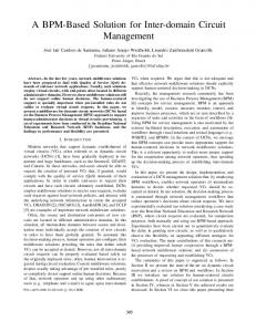
Constructing a BPM Environment with BPMN*. Ching-Hong Tsai, How-Jen Luo and Feng-Jian Wang. Department of Computer Science, National Chiao-Tung ...
Constructing a BPM Environment with BPMN*
Ching-Hong Tsai, How-Jen Luo and Feng-Jian Wang Department of Computer Science, National Chiao-Tung University,Taiwan {chtsai,jrluo,fjwang}@cs.nctu.edu.tw
Abstract Workflow at its simplest is the movement of documents or tasks through a work process with automation for achieving certain goals. Many efforts have been spent by both industry and academia in attempting to define a common representation of a business process based on the concept of workflow. In 2005, Business Process Modeling Notation (BPMN) is a business process language developed by OMG & WfMC which satisfies the goal. However, BPMN supports only the concepts & notations for modeling. Several real concerns for business purposes are out of scope of BPMN. Besides, it needs many efforts for the implementations of a BPMN environment. Here we present one simple approach to construct a Business Process Management System, BPMS, based on BPMN. In our approach, we developed a conceptual workflow model, BPMN*, a BPMN with some constraints, for the specification of a BPMs. The BPMN* specification is then translated into another specification, based on Cooperative Agentflow Process LANguage (CA-PLAN) and executable in a WFMS, Agentflow, developed in our laboratory. We have developed a specification tool for BPMN*. In the future, we will examine the functions of the tools in Agentflow based on BPMN* and upgrade the related feature for necessity .
1.
Introduction
Workflow at its simplest is the movement of documents or tasks through a work process with automation for achieving certain goals. Different vendors implement Workflow Management System (WfMS) in different ways. A WfMS works for people from different domains, while most of the workflow notations are designed for technical developers and thus hinder the communication and mutual understanding among developers and stakeholders.
Proceedings of the 11th IEEE International Workshop on Future Trends of Distributed Computing Systems (FTDCS'07) 0-7695-2810-4/07 $20.00 © 2007
Business Process Modeling Notation (BPMN) [1] is developed by Business Process Management Initiative (BPMI) as a standardized graphical notation, which satisfies these demands, and thus provides the construction of SOA [11]. However, BPMN supports only the modeling concepts that are applicable to business processes. In this paper, we propose a simple way for the development of Business Process Management BPM (or WfMS) by integrating BPMN with existent WfMS. Agentflow [2] is developed by our laboratory that is mainly based on Cooperative Agentflow Process LANguage (CA-PLAN) [4] and several prior researches. It has been implemented in practical distributed WfMS’s for years and consequently the importance of its features is shown. [3] In the beginning of the paper, we propose a modification of BPMN, named BPMN*, by adding several constraints to delete some conflicts and obscure notations in the latest version of BPMN. These works are done on BP flow objects, swimlanes and connecting objects, The BPMN* is then integrated with CA-PLAN for constructing a complete BPM model, BPMN-PLAN. The specifications in BPMN-PLAN can be translated into CA-PLAN so that they can run on Agentflow. In this paper, Section 2 introduces BPMN, execution platform with frameworks, and related process modeling/analysis languages. Section 3 depicts BPMN* and how BPMN* cooperate with CA-PLAN, and section 4 provides a simple case study to show the whole development process with BPMN*. Finally, conclusion and future works are made in the section 5.
2.
Background
BPMI standardizes a set of modeling notations, named BPMN, by applying many different modeling concepts and viewpoints. BPMN consists of both the graphical notations and the semantics of a so-called
Business Process Diagram (BPD). BPMN is based on flowcharting techniques and consists of four categories: Flow Object, Connecting Object, Swimlane, and Artifact, and two modularization elements: Process and BPD (A BPD is also used to represent a definition instance of BPMN). BPMN is an evolving standard of process logic specifications for the business process management languages such as BPEL(BPEL4WS) [5] and Business Process Modeling Language (BPML) [6]. Agentflow system developed by our laboratory is a typical WfMS. It provides workflow designers an integrated developing environment during design time, and a running server and environment for automated process enactment, process control, execution monitoring, and database management for workflow participants during run time. It consists of Workflow Engine, Process Aid Software engineering Environment (PASE), Process Definition Environment (PDE), and Agenda. The software process model, Process LANguage (PLAN) [7] [8] in Agentflow is used to model the software development project with how activities are performed by the people (roles), supplied with the resources, and lead to the product (artifact). In CA-PLAN, an extended version of PLAN for a Process Transition Diagram (PTD), depicts the behavior of a process. It consists of a start point, an end point, processes (nodes), and transitions (links).
3. Business BPMN*
Process
Modeling
with
In this section, BPMN* is introduced first. Then, BPMN-PLAN, an integration of BPMN* and CA-PLAN is discussed.
BP Activity is called an interrupt event, while the rest of the intermediate events are called halt event. An interrupt event is associated with an interruption handling routine that reacts to the designate triggers. A halt event is placed in normal flows to halt the flow and represents an expected delay or waiting. The halted flow is not recovered until the designate trigger occurs. In addition, for the readability of a process diagram, each process in BPMN* must explicitly designate start events and end events. For example, the second diagram in Figure 3_1 has an implicit start event, and it is forbidden in BPMN*.
Figure 3_1 Explicit and implicit start event example o BP Activity In BPMN, an activity of sending or receiving messages is also defined as an event. These definitions for event and activity concepts are confused. It is clarified in BPMN* as followings: When the source or target of a message flow is an activity, there is a corresponding sending or receiving event implicitly. For example, both diagrams in Figure 3_2 are equivalent. In general, the second diagram is adopted, however, the first is recommended in case end event results summarize the process. Therefore end and intermediate (halt) event constraints are applied to send and receive tasks accordingly.
3.1. BPMN* To reduce the ambiguity within BPMN and simplify the development process, several constraints and clarifications are introduced here. In addition, the resultant version, BPMN*, is conformable to BPMN. In the following paragraph, the modified notations are described, while the directly inherited ones are left out. The name of each category in BPMN* is extended with prefix "BP" to differentiate from the terms we used in CA-PLAN (e.g. the term "BP Artifact" differs from the artifact in CA-PLAN). • BP Flow Object o BP Event In BPMN, there are three types of events: start, end, and intermediate events. An intermediate event may behave in two ways, which shall be defined separately. In BPMN*, the BP Event associated with a
Proceedings of the 11th IEEE International Workshop on Future Trends of Distributed Computing Systems (FTDCS'07) 0-7695-2810-4/07 $20.00 © 2007
Figure 3_2 BP Event and BP Message Flow example Besides, the pre-condition and post-condition based on additional attributes are added into each BP Activity to constrain the starting and the normal finishing (since there may be an interruption) conditions accordingly. o BP Gateway In BPMN, there are one implicit and four explicit gateways, which are not distinctively differentiated from each other. Moreover, a contradiction in BPMN specification (exclude gateway used in merging in p.75 & p.119 [1]) is admitted by the author. In BPMN*, gateways are reclassified into six classes: 1) exclusive (data-based XOR), 2) event (event-based XOR), 3) inclusive (OR), 4) parallel
(AND), 5) uncontrolled, and 6) complex. An uncontrolled gateway is abstracted from BPMN, which represents the gateway which contains no control capabilities, like an exclusive or merge node in the workflow pattern [10]. It is classified as a gateway because of the essence of BP Gateways that all splitting and joining of the flows shall be under the control of gateways.
Remote Domain
Local
Workflow
Process Service
Workflow sub-activity
Resourc e
Remote Process
refers
sub-artifact
manipulate
perform Activity
Role
supplie
change Action coordinates
triggers
Process Transitions
remote
controls
Artifact Artifact Attribute
show s
Model
defines refers to Artifact State
e-Form Form View
switche
Form Data Model change Form Action
control
Figure 3_3 Example of uncontrolled gateway Each of the six types of gateways may function as split (branch) or join (merge). • BP Swimlane Each process is contained within a BP Pool, which represents a distinct domain. For each BPD of the collaboration sub-models (i.e. private, abstract, and collaboration process), there shall be at least one BP Pool specified for local domain. In our cases, a BP Pool is used to indicate a WD. As for the BP Lane, it is preserved for attribute assignments and annotations. • BP Connecting Object A BP Message Flow may be considered as a control flow which synchronizes the processes among business entities. It is named synchronous flow and definitely specifies the sequences of processes among business entities. Otherwise, it is used to merely represent the communicative behavior of processes, and named as communication annotation.
3.2. BPMN-PLAN
Our experience of applying Agentflow and CA-PLAN in real world BPM environments indicates that organization structures, artifact states, e-forms and service-oriented collaboration also are essential for a practical business scenario. Therefore, BPMN-PLAN, an extension of BPMN*, is proposed.
Proceedings of the 11th IEEE International Workshop on Future Trends of Distributed Computing Systems (FTDCS'07) 0-7695-2810-4/07 $20.00 © 2007
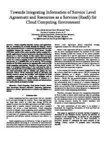
Process Event
Figure 3_4 BPMN-PLAN meta-model A workflow domain (WD) is classified as the primary entities for the collaborations of BPMN-PLAN. An organization can be divided into several sub-organizations of which each belongs to one or more WDs. Each domain contains its own process definition and runtime repository for WfMSs running accordingly. An activity manipulates one or more artifacts by reading or modifying its states. It might be defined as a computer program or a human activity. The process event is drawn out from process transitions for abstracting time stamps of business process. It is explicitly designated and expected to happen during runtime. The collaboration mechanism of BPMN-PLAN is based on Remote Call Process (RCP) mechanism, where a collaboration (inter-organization) process is partitioned into several private (intra-organization) processes. A process service is a mechanism that packs a set of processes. It can be used to provide service for the process(es) in the WDs being cooperated. A remote service (process) is used when a local process attempts to cooperate with the processes in another WD; the local process uses remote service to refer to the process services provided by other WDs. An artifact stands for the abstractions of data instances within the business process. Semantically, an artifact can be deemed as a finite state automaton. Besides representing life cycle of artifacts, artifact states can be used to simplify the influences of data instances on process behaviors (e.g. Boolean expression of artifacts can be used as pre-condition and post-condition of activities). An e-Form is a group of artifacts. For example, an e-Form contains a set of paper documents. The form data model refers to and manages access controls of artifacts associated with the form. The form view depicts the representation of the form data model. An
e-Form might have more than one presentation (e.g. JSP or Applet). The form action describes the interaction between users and the form. Resources are any type of entities other then above, for example, hardware machine, software component, laborer, etc. On the other hand, a BPMN-PLAN model contains the following sub-models: Process Behavior model, Role model, Artifact model, Form model, and Resource model. Each of them provides distinct perspective for a business process. And an additional mechanism is given to bind related sub-models into a project module.
rebated to the customer. As soon as redeployment completes successfully, the goods are delivered and the invoices are filed. At last the reply of successful delivery notification is sent to customer. The results are indicated as followings: z Process behaviors The process behavior is specified as a BPMN* (or BPMN-PLAN) diagram in Figure 4_1.
Role model performs activity of Process Behavior model Process model
manipulates Artifact model shows
supplies activity of
Form model Inherits CA-PLAN
from
Resource model
Figure 3_5 BPMN-PLAN sub-models and relationships
4.
Case study
In this section we take an example to demonstrate how to develop a BPM with BPMN-PLAN. We also use an algorithm to transfer BPMN-PLAN into CA-PLAN. The description of the algorithm is in [9].
4.1. Requirement specifications Our approach to specify the requirements based on BPMN-PLAN contain two major steps. The first is to draw BPMN-PLAN diagram(s) is drawn to display the process behaviors according to user’s requirements. Then, the sub-models are built correspondingly. For example, let us define the process specification from the perspective of trading system. The orders from customers are presumed to be handled by front-end systems, such as a web shopping system. Thereby the interactions between the trading system and its customers can be simplified as events. A trading process in Figure 4_1 is triggered by the order from a customer which has been validated by a front-end system. The trading system then consults the bank for confirming the payment. If the remittance is not confirmed, a failed notification is sent to the customer and the process terminates; otherwise the system starts to redeploy the ordered goods. In case the order is canceled during redeployment, the payment is
Proceedings of the 11th IEEE International Workshop on Future Trends of Distributed Computing Systems (FTDCS'07) 0-7695-2810-4/07 $20.00 © 2007
Figure 4_1 Trading process
4.2. System design From the requirement specification, there are several artifacts, roles, and e-forms can be discovered. The methodology to analyze the requirement and elicit these objects from the requirement is beyond the scope of this paper. We just simplify the whole methodology in brief. Review the Figure 4_1, the gateway object contains the conditions which may affect the branching of the process. Some information must be recorded in the process. We summarize the information, includes: Reference data instances z Customer information z Deliver address, contact methods z Payment account, rebate account z Goods information z Goods ids, quantity, price z Invoices z Process information z Checking result (boolean) The information must be carried by an artifact and represented in an e-form, suppose there is only one e-form representing the information:
E-Forms z Goods deployment form (GDF) From the requirement, since there are two pools the Figure 4_1, there are at least two roles in the system. From the left pool in the Figure 4_1, it shows the process communicating between customer and the trading company, so the roles in this system includes: Roles z Customer z Trading system z Banking system To define the process clearly, we fill detail information in following tables: Table 4_1 Process events Event Trigger/ result Incoming order An order (message from the (start event) customer) is received. Fail notification The notification is sent. (end event) Cancel interrupt The cancel notification is (interrupt event) received during deployment. Cancel notification The notification is sent. (end event) Success notification The notification is sent. (end event) Table 4_2 Process stages Process stages Start condition Order checking The order is received. Goods redeployment
The order checking result is confirmed. (checking result = T)
Order canceling
The redeployment is canceled. The order is canceled.
Rebating Delivery Invoice making
The goods are deployed. The goods are deployed.
End condition The order checking has been done. The goods have been deployed or the order has been canceled. (deployment result=T or F) The order has been canceled. The payment has been rebated. The goods have been delivered. The invoices have been made.
4.3. Translation In the translation, the collaboration processes are recomposed first. There are two remote processes
Proceedings of the 11th IEEE International Workshop on Future Trends of Distributed Computing Systems (FTDCS'07) 0-7695-2810-4/07 $20.00 © 2007
defined for the trading in the banking system. One is the "remittance checking" process which interacts with the "order checking" process. The top BP message flows in Figure 4_1 is considered as communication annotations and the "order checking" process is considered as a service task. The other is the "rebating" process executed after order canceling process. The bottom BP message flows in Figure 4_1 are then combined as a synchronized message, which is transformed into an independent process named "rebating request". The result of this phase is showed in Figure 4_2. Note that if the process behavior is specified with BPMN, the modeler will likely be confused with the execution sequences of local and remote processes.
Figure 4_2 BPD after first phase In the second phase, the embedded process, i.e. "goods redeployment" process, is done complete. It is expanded as in left part of Figure 4_3, which contains a loop that keeps checking if all the ordered goods are in inventory. If all the ordered goods are in stock, the redeployment process ends. Otherwise the process is halted to wait for replenishment notification. The algorithm handles the redeployment process as follows. 1. Expand gateways The exclusive gateway is replaced with a dummy task whose post-condition is the exclusive constraint of exclusive gateway. 2. Transform halt events
3.
The halt event is transformed into a receive task which listens to each notification of replenishment. Arrange sequence flow conditions The conditions of BP Sequence Flows after the dummy task are associated with post-condition of the dummy Task.
4.
Figure 4_3 Goods redeployment Now, the transferring of the rest sub-processes in trading process in Figure 4_2 continues as follows. 1. Remove ignorable commentaries All the three annotations and associations are removed. 2. Join start and end events The start event with a message trigger is transformed into an initiate event and a message halt event as in Figure 4_4.
Figure 4_4 Join start events There are three end events in the trading process, which represent "remittance confirmation failed", "trade successful completed", and "redeployment aborting". They are replaced with corresponding tasks and linked with BP Sequence Flows to the additional complete event as in Figure 4_5.
3.
Figure 4_5 Join end events Expand interrupted routines The interrupted event associated with goods redeployment process is expanded to an event gateway as in Figure 4_6.
Proceedings of the 11th IEEE International Workshop on Future Trends of Distributed Computing Systems (FTDCS'07) 0-7695-2810-4/07 $20.00 © 2007
5.
6.
Figure 4_6 Expand interrupt routines Expand gateways The exclusive gateway, event gateway (generated in previous step), and parallel gateways are expanded as in Figure 4_7 correspondingly. Note that the expansion of the event gateway generates a process variable, redeployment result, which constrains the exclusive behavior of the branches.
Figure 4_7 Expand gateways Transform halt events There are two halt events generated by expanding event gateway in step 3. They are transformed into two receive tasks which wait for the normal completion or cancelation trigger of goods redeployment process.
Figure 4_8 Transform halt events Arrange sequence flow conditions The condition of each BP Sequence Flow is scattered over the pre-condition of its
downstream BP Activities and the post-condition of its upstream BP Activities. After second phase, the BPD has been transformed from Figure 4_2 into BPMN* notation, which can be one-to-one mapping to PTD in Agentflow.
Figure 4_9 Mapped PTD
5.
Conclusion and future works
This paper presents a conceptual business process model by integrating CA-PLAN with a modified notation of BPMN, BPMN*. Compared with BPMN, BPMN* contains less ambiguity of the obscure notations within BPMN, and BPMN-PLAN introduces some ideas/notations in Agentflow to model practical business processes. However, some notations of BPMN are excluded from BPMN*, which may reduce the latter’s expressive power. For instance, the inclusive merge gateway is excluded from BPMN* for its uncertainty in design time. It is necessary to study the complementary issues for BPMN* We are working on the construction of an editorial environment for BPMN*. After it is put into practice, the development of related techniques such as analyzing and testing for a BPMN* developed system will be our next topic. Since BPMN is still in evolving, BPMN* will need to be continuously studied to advance the compatibility in the future.
Proceedings of the 11th IEEE International Workshop on Future Trends of Distributed Computing Systems (FTDCS'07) 0-7695-2810-4/07 $20.00 © 2007
6. [1]
Reference
Object Management Group, "Business Process Modeling Notation (BPMN) Specification", Final Adopted Specification, February 2006 [2] Flowring Technology Corp, Agentflow system, http://www.flowring.com [3] Shung-Bin Yan and Feng-Jian Wang, "A Cooperative Framework for Inter-Organizational Workflow system", In Proceedings of the 27th Annual International Computer Software and Applications Conference (COMPSAC'03), Nov. 2003 [4] Shung-Bin Yan and Feng-Jian Wang , "CA-PLAN, an inter-organizational workflow model", International Journal of Automation and Computing 2 (2005) 195-207, September 2005 [5] "Business Process Execution Language for Web Service", version 1.1, http://www.ibm.com.developeworks/library/ws-bpel, May 2004 [6] Business Process Management Initiative, "Business Process Modeling Language", Nov 2002 [7] Ming-Feng Chen, Bin-Shiang Liang, Feng-Jian Wang. "A Process-Centered Software Engineering Environment with Network Centric Computing", 6th IEEE Workshop on Future Trends of Distributed Computing Systems (FTDCS ’97), pp.234, 1997. [8] Yin-Shinn Chen, Feng-Jian Wang. “An Editing System for Working Processes”, 25th Annual International Computer Software and Applications Conference COMPSAC’01), pp. 332, 2001. [9] How-Jen Lo, “Integrate BPMN* with a WfMS”, Master’s Thesis, Department of Computer Science, National Chiao-Tung University, Taiwan, July, 2006 [10] Steven A. White, “Process Modeling Notations and Workflow Patterns”, www.bptrends.com, March 2004. [11] Heather Ashton, David Kelly, “The Business Impact of BPM with SOA”, http://www-306.ibm.com/software/info/bpmsoa/pdf/UR -IBM-BPM_Business_Case-Final-1.pdf, 2006