dominant orientation like hair. This paper ... texture with a dominant orientation such as hair, than in a ... Texture discrimination is one of the most difficult tasks.
Content-based Digital Watermarking using Contrast and Directionality Nam-Deuk Kim and Alastair Reed Digimarc Corporation Tualatin, Oregon, USA Abstract Human visual system (HVS) models have been used in digital watermarking to minimize the visual effects of the watermark while increasing the strength of watermark. Such work has been applied to different watermarking schemes with varying degrees of success. Previous work at Digimarc resulted in a HVS model that inserts a high watermark signal in busy or high contrast areas, while reducing the watermark on connected directional edges where it becomes more visible. In certain instances, however, this technique inserts a high watermark signal in a region where masking due to the image is insufficient to hide the signal. For example, the watermark becomes apparent in areas with fine texture containing a dominant orientation like hair. This paper introduces a new HVS model, based on techniques that identify areas with a dominant orientation and suppress the watermark gain for those regions. Once a contrast is computed, another measurement (called directionality) is made on a small neighborhood using a standard wavelet filter set and a rotated wavelet filter set to determine if the region is highly oriented in one direction. The watermark strength gets suppressed if the corresponding area has high contrast and high directionality measure, while the gain reaches the maximum when the area has high contrast and low directionality measure. Experiments on problem images show that the proposed technique remedies the limitations of the previous HVS model to some extent, while not degrading the watermark detection performance.
Introduction Digital watermarking is a process for modifying physical or electronic media to embed a machine-readable code into the media. This embedded information can be used in many ways, for example to provide copyright information, to prevent illegal duplication, or even as a dynamic link between the image and online digital data. For most applications, the image owner would like to make the encoded data robust enough to ensure its detection while maintaining the high quality of the original image.
However, increasing robustness usually implies a larger watermark signal that in turn leads to greater image degradation. In order to minimize the visual effect, many watermarking schemes use a human visual perceptual model to identify how much watermark signal various image areas can hold while maintaining equal visibility. A major component of such a model is to measure local image contrast, and map increasing contrast values to a larger watermark signal [1,2]. This can present a problem in some high contrast areas that contain directional edges. For example, the eye is much more sensitive to watermark signal added to an edge separating two distinct objects or a texture with a dominant orientation such as hair, than in a random texture of the same contrast. In previous work at Digimarc [3], we inserted a high watermark signal in high contrast areas, while reducing the strength on connected directional edges. A modified Canny edge detector was used for finding connected directional edges. The modified Canny method suppressed the signal strength on edges separating two distinct objects, but not in a texture with a dominant orientation. In the new method described in this paper, the watermark signal is suppressed on both edges separating two distinct objects or a texture with a dominant orientation such as hair. High contrast areas with a dominant orientation are detected by measuring directionality in a small neighborhood, using a standard wavelet filter set and a rotated wavelet filter set [4]. The watermark signal is then reduced for these directional high contrast areas. Experiments on problem images show that the proposed technique based on perceptual models remedies the limitations of the previous HVS model to some extent, while not degrading the watermark detection performance. In the next Section, wavelet-based texture analysis is briefly described and a set of rotated wavelet filters is introduced. Computing rotation-invariant directionality measure of a texture image by using wavelet filters and its application to watermarking are presented in the following Section, which is followed by Results and Conclusions Sections.
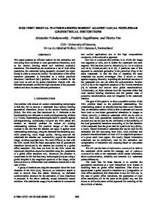
Wavelets and Texture Analysis Texture discrimination is one of the most difficult tasks among low-level computer vision problems [5]. Although textures are quickly preattentively discriminated by a human observer [6], appropriate models for textures do not exist. The perception of texture depends on local but not pointwise properties. However, a prescriptive procedure for selecting the neighborhood size over which textures can be analyzed is not available. This has motivated the use of a transform with which image properties are measured over domains of varying sizes. Psychophysics, and physiological experiments [7] have shown that multiscale/multiresolution transforms seem to appear in the visual cortex of mammals. Haar and Gabor wavelet decompositions, and Gaussian and Laplacian pyramids are examples of multiscale decompositions. In the last decade, wavelet theory has emerged and now provides a solid and unified framework for multiscale image analysis, making it a preferred tool because of several conceptual and computational advantages [8]. This is the reason why we chose wavelet transforms for texture characterization in this study. Discrete Wavelet Transform (DWT) A commonly used method for 2-D DWT implementation involves a successive application of 1-D QMF filters h and g along the columns and rows of the image. The subimages resulting from such operations to an image A are three detail images AHL, ALH, and AHH and an approximation image ALL, where the subscript denotes the frequency information of the rows and the columns, respectively. This process is repeated iteratively on the approximation image ALL, with a translated and dilated version of basis functions for each consecutive scale to obtain multi-resolutional information. The 2-D DWT can be also performed by using four 2-D filters that could be obtained from tensor product of h and g filters. An example of one level 2-D DWT for a “Lena” image is shown in Fig. 1. Vertical (lower left), horizontal (upper right), and diagonal (lower right) details are clearly seen in corresponding subimages. The energy distribution of these subimages is known to be an important characteristic for texture analysis [8]. The energy is computed as follows: εk =
1 MN
M −1 N −1
∑∑ y m
k (m, n)
2
,
Figure 1. An example of one level discrete wavelet transform. From upper left (clockwise), ALL, ALH, AHL, and AHH.
Rotated Wavelet Filter Bank The rotated wavelet filter bank (RWFB) was introduced by Kim and Udpa [4] to provide complementary texture information to the texture information obtained by a standard wavelet filter bank (SWFB) for a texture classification application. Although fine orientation selectivity can be also obtained by using Gabor wavelet filters or non-separable oriented wavelet transforms [9, 10], RWFB is used in this study for simplicity and efficiency reasons. Four rotated filters are obtained by rotating each of four standard 2-D wavelet filters by 45 degrees, hence the image decomposition is performed in the direction of 45 and 135 degrees. This decomposition process also results in three detail images and one approximation image. For visual understanding, the frequency partitioning of AHL and ALH from SWFB and RWFB are presented in Fig. 2.
(1)
n
where M and N are the width and length of the subimage y k (m, n) . However, the diagonal subimage (AHH) contains information of two diagonal directions (45o and 135o) simultaneously, and this limits the orientation selectivity that is useful for the applications where rotation-invariant features are needed. In this study, a rotated wavelet filter bank [4] is used to add orientation selectivity to the standard DWT.
Figure 2. Frequency partitioning for standard (upper row) and rotated (lower row) wavelet filters that correspond to subimages AHL (left column) and ALH (right column).
Directionality Measure In this section, we describe techniques for measuring rotation-invariant directionality of the texture image and its use in digital watermarking as a part of the HVS model. Rotation-Invariant Directionality Measure For directional textures (texture with a dominant orientation), the energies of ALH and AHL vary significantly when the texture image gets rotated. The patterns of energy variations for the two subimages are 90 degrees apart from each other. Let D(ε HL − ε LH ) represents the energy difference between two subimages AHL and ALH, where D(a,b) = |a-b|. In the SWFB case, energy of AHL is maximum for a texture with pure vertical lines in it, while energy of ALH is almost zero. For a texture with horizontal lines, it works in the opposite way. The energy difference (D) between AHL and ALH for those textures becomes the maximum. However, if this texture image is rotated by 45 degrees, the energy of AHL and ALH is almost identical, resulting in minimum D. Likewise, the D from a single filterbank cannot serve as a rotation-invariant feature. The deficiency can, however, be met by introducing D from RWFB where the energy difference is obtained from the 45 degrees shifted in frequency regions. For example, if a texture that is strongly directional in vertical direction is rotated by 45 degrees, the D from SWFB reaches at its minimum, while that from RWFB reaches at its maximum. Hence, the combination of the energy difference between subimages AHL and ALH from both filter banks is expected to be constant, when each difference is properly normalized. This approximates the directionality of texture, and we call this DM (directionality measure). The DM is computed as follows: D(ε HL − ε LH ) D(ε HL − ε LH ) (2) DM = + ∑εk ∑εk k =HL,LH,HH SWFB k =HL,LH,HH RWFB
Application to Watermarking A contrast map is obtained by the method described in [3], and a directionality map was computed by using equation (2). Then, regions where watermark strength needs suppression are identified by combining the contrast and directionality maps. Regions with high contrast and high directionality are considered for suppression. The watermark strength gets suppressed as follows: ( K − DM ) × Contrast ,
(3)
where K is a constant that a user defines depending on the amount of suppression. In this paper, K was 1.3. Thus the maximum watermark signal can be hidden in random textured areas, while visible artifacts in directional high contrast areas are avoided.
Edge
Watermark Signal Element (a)
(b)
Figure 3. Visibility reduction along dominant edges using perceptual modeling based on directionality. (a) before and (b) after suppression.
Directionality was computed over disjoint blocks, size of 6×6 for 300 dpi images. The block size changes depending on the image resolution. Since the directionality is computed over a small block size, its responses over edges whose thickness is smaller than the block size is also significant. Hence, directionality measure becomes high over regions where strong edges and texture with dominant orientation exist. After the combination of the two maps, non-linear contrast to gain mapping is performed to output final gain map (see [3] for more detail). Fig. 3 illustrates an example showing how directionality based perceptual modeling reduces visibility of the digital watermark signal along image edge features. The left diagram illustrates a case with no perceptual modeling at edge features. In this case, the watermark signal elements fall along an edge, potentially creating noticeable artifacts due to the break up of the edge. In the right-hand side diagram, the digital watermark signal elements are suppressed along the edge based on the directionality measure. This diagram shows the extreme case where the watermark signal is completely suppressed along the edge. The watermark signal elements may be reduced by a lesser degree, by adjusting the gain applied to them for example, depending on the values of the directionality measure and the local contrast measure as explained above.
Results An artificial image was created in Figure 4a to illustrate the operation of the new perceptual masking algorithm. The straw on the left hand side of the image is a texture with strong directionality, whereas the pattern on the right hand side is random without any preferred direction. Figure 4b shows the result of adding a watermark signal with our old algorithm described in [3]. The watermark visibility is worse on the left hand side of the image that has strong directionality. However the watermark is not very visible in the random texture on the right hand side. The result of using our new algorithm to add the watermark signal, at the same strength, is shown in Figure 4c. The watermark signal is suppressed on the left hand side that has strong directionality, while the strength of the watermark in the
a
b
a
b
a
c
d
Figure5. Watermarked image with (left) and without (right) proposed method (watermark accentuated for effect).
Figure4. Watermarked images using old and new HVS models. (a) original image; (b) watermarked using an old model with a gain 5; (c) watermarked using a new model with a gain 5; (d) watermarked using a new model with a gain 7 (watermark accentuated for effect).
random texture on the right hand side remains about the same as before. The visibility of the watermark in the directional and random texture areas is then approximately the same. This allows the overall signal strength to be increased as shown in Figure 4d, resulting in detectability which is about the same or better than the old method in a real image. A baby hair image has shown visibility problems when strongly marked, and this image was used for verification of the new HVS model. The snowy artifacts that appeared in the baby’s hair (Fig. 5a) are not significant in Fig. 5b for which the proposed perceptual masking was applied. The new algorithm seems to successfully improve the visibility by suppressing watermark strength in directional edge regions. This improvement was observed from multiple experiments on various types of images.
improvement in the problem regions, without sacrificing the overall detection rate. In practice, a user will limit the watermark strength to avoid any image artifacts that limit the overall signal. The new algorithm allows an overall watermark strength to be higher before any artifacts are seen. The small signal loss on the directional edges is more than compensated by overall higher watermark strength leading to improved detectability.
Acknowledgments The authors would like to thank Tony Rodriguez, Kevin Hewitt, John Stach, Don Haaga, Lou Berkley, Eric Hudson, Peter Harmon and Joel Meyer of Digimarc for their help in contributions to this paper.
References 1.
2. 3.
Conclusion We have proposed an improved HVS model based on perceptual masking of a digital watermark signal in an image signal. A proposed model for digital watermarking identifies areas of dominant orientation within an image and modifies the watermark gain for those regions to minimize perceptibility of the digital watermark. The perceptual masking model computes local contrast and measures directionality of image features in small neighborhoods using a standard wavelet filter set and a rotated wavelet filter set. Results from the new HVS model showed visibility
4.
5. 6.
C.I. Podilchuk and W. Zeng, Image-adaptive watermarking using visual models, IEEE J. Selected Areas in Communications, Vol. 16, pg.525-539, May 1998. Peter G.J. Bartens, Contrast Sensitivity of the Human Eye and Its Effects on Image Quality, pg.147- 151, SPIE Press, 1999. Brett T. Hannigan, Alastair Reed, and Brett Bradley, Digital watermarking using improved human visual system model, presented at SPIE Electronic Imaging 2001 in San Jose, pg. 468-474, Jan. 2001. Nam-Deuk Kim and Satish Udpa, Texture classification using a rotated wavelet filterbank, IEEE Trans. on Sys., Man, and Cyber., Vol. 30, No. 6, pg.847-852, 2000. S. Mallat, Wavelets for Vision, Proc. of the IEEE, Vol. 84, No. 4, pg.604-614, 1996. J. Malik and P. Perona, Preattentive texture discrimination with early vision mechanisms, J. Opt. Soc. Amer., Vol. 7, pg.923-932, 1990.
7.
J. G. Daugman, Two-dimensional spectral analysis of cortical receptive field profile, Vision Res., Vol. 20, pg.847-856, 1980. 8. S. Livens and P. Scheunders and D. W. G. Van and D. D. Van, Wavelets for texture analysis, an overview, IEE Conf. Image Proc. and Anal., July, pg.581-585, 1997. 9. E. P. Simoncelli and E. H. Adelson, Non-separable extensions of quadrature mirror filters to multiple dimensions, Proc. of the IEEE: Special issue on Multi-dimensional Signal Processing, Vol.78, No.4, pg.652-664, 1990. 10. W. T. Freeman and E. H. Adelson, The Design and Use of Steerable Filters, IEEE Trans. Patt. Anal. and Machine Intell., Vol. 13, No.9, pg.891-906, 1991.
Biography Nam-Deuk Kim received his B.S. degree in computer engineering from Kwangwoon University, Seoul, Korea in
1992, M.S. and Ph.D. in electrical engineering from Iowa State University in 1995 and 2000, respectively. Since 2000 he has been working at Digimarc Corp. as an R&D engineer. His research topic includes digital watermarking, image/video compression, texture analysis, medical imaging, and pattern recognition. Alastair Reed received his B.Sc degree in Physics from Imperial College, London in 1975 and a Ph.D. in Physics from the Polytechnic of North London in 1979. He went on to do color image processing for 5 years at Crosfield Electronics in Hemel Hempstead, England and 12 years at CSI in Richmond, Canada before coming to Digimarc in Portland, Oregon 2 years ago. His work at Digimarc has involved modeling the human visual system and the print process, to reduce watermark visibility.