mance and help disadvantaged flows get better throughput. A modification of the MAC layer will let each station estimate network condition and determine ...
Contention Window Size Control for QoS Support in Multi-Hop Wireless Ad Hoc Networks Pham Thanh Giang and Kenji Nakagawa Department of Electrical Engineering, Nagaoka University of Technology, Kamitomioka 1603–1, Nagaoka-Shi, Niigata, 940–2188 Japan, {giang@kashiwa, nakagawa@}.nagaokaut.ac.jp Abstract. IEEE 802.11 MAC protocol for medium access control in wireless Local Area Networks (LANs) is the de facto standard for wireless ad hoc networks, but it does not necessarily satisfy QoS requirement by users such as fairness among flows or throughput of flows. In this paper, we propose a new scheme aiming to solve per-flow fairness problem and achieves good throughput performance in IEEE 802.11 multi-hop ad hoc network. We apply a cross-layer scheme, which works on the MAC and link layers. In the link layer, we examine each flow and choose suitable contention window for each output packet from the flow. The aim of the mechanism is achieving per-flow fairness. In our proposed scheme, the MAC layer of each station tries to evaluate network condition by itself then adjust channel access frequency to improve network utilization and ensure per-node fairness. Performance of our proposed scheme is examined on various multi-hop network topologies by using Network Simulator (NS2). Keywords: cross-layer, per-flow/per-node fairness, bandwidth utilization, multi-hop wireless, IEEE 802.11.
1
Introduction
In multi-hop ad hoc network, throughput and fairness performances are very important. However, IEEE 802.11 standard [1] does not provide good throughput and fairness for stations in some asymmetry topologies [2, 3]. When stations cooperate to forward packets from other stations through the ad hoc network, each station has to transmit both the direct flow, which is generated by the station, and forwarding flows, which are generated by its neighboring stations. The station also shares the channel capacity with its neighboring stations. The contentions in the MAC and link layers affect the performance of the network. Due to the MAC layer contention, the allocated bandwidth for each station cannot ensure per-flow fairness. In the link layer, the direct flow and forwarding flows contend for the buffer space. Obviously, the direct flow gets more advantage than forwarding flows [4–6]. In this paper, we propose a new scheme in order to achieve good fairness in both the MAC and link layers. We also aim to ensure good throughput performance and help disadvantaged flows get better throughput. A modification of the MAC layer will let each station estimate network condition and determine
fair bandwidth allocation for them. By tuning back-off time, they can get suitable allocated bandwidth. In the link layer, we use Round Robin (RR) queue for each flow, and monitor output packet to ensure per-flow fairness. We use the Network Simulator (NS) [7] to evaluate our proposed scheme in some unfairness situations relying on some asymmetry topologies. The rest of the paper is organized as follows: Section 2 reviews some related works. Section 3 describes our proposed scheme. Section 4 evaluates our proposed scheme by comparing with original FIFO scheduling in IEEE 802.11 standard [1], Shagdar’s method [5] and PCRQ scheduling [8]. Finally, Section 5 concludes the paper.
2
Related work
The fairness performance at the MAC layer has been an active research field in the past several years. The protocols MACA [9] and its extension MACAW [10] use the four-way RTS/CTS/Data/ACK handshake signals to reduce collisions caused by hidden terminals in the network. The protocol MACAW has been standardized in the IEEE 802.11 [1] as Distributed Coordination Function (DCF). However, the RTS/CTS scheme in DCF does not solve all unfairness in bandwidth in case of asymmetric links. Several schemes for improving the fairness of MAC protocol have been proposed in the literature [11–13]. Moreover, Li et al. [14] investigated Extended Inter-Frame Spacing (EIFS) problem, i.e., the fixed EIFS value leads to unfair bandwidth allocation for each stations. They proposed flexible EIFS values based on a measurement of the length of Sensing Range (SR) frame. However, the length of SR frame cannot be always recognized because of the spatial reuse of the bandwidth. Moreover, those research mainly consider the MAC layer fairness problem, they do not consider per-flow fairness problem. Jangeun et al. [4] pointed out the weak point of FIFO scheduling in multi-hop networks and then proposed various queuing schemes. Each scheme has offered different degree of fairness. However, their research is based on the ideal MAC layer fairness assumption that cannot be satisfied. Thus, their schemes do not give good performance in the real networks. Shagdar et al. [5] and Izumikawa et al. [6] also focused on the contention of direct and forwarding flows, and proposed scheduling algorithms by using RR queue. The DCF mechanism are modified in [5] to achieve the bandwidth utilization by sending all the packets at the head of RR queues continuously without delay by back-off algorithm. However, their solutions have the same problem as [4] due to the unsatisfactory assumption that the MAC layer gives fair bandwidth allocation. PCRQ scheduling [8] also uses RR queue with three algorithms to control input/output packets and the turn of RR queue. It achieves good result in per-flow fairness. In PCRQ scheduling, the MAC layer fairness is also improved indirectly because PCRQ scheduling gives a delay for a packet from heavy flows in order to help disadvantaged flows get a chance in using channel bandwidth. However, it slightly degrades the total throughput performance.
3
Proposed Scheme
The reason of unfairness problem in multi-hop ad hoc network is due to both the MAC and link layers contention. In this section, we propose a scheme to
improve per-flow fairness in wireless ad hoc networks. In the MAC layer, we make a minor modification to the original DCF channel access mechanism to help each station can achieve suitable allocated bandwidth. In the link layer, we use RR queue with a monitoring algorithm to ensure fair between flows. 3.1
MAC Layer Modification
In IEEE 802.11, the DCF algorithm behaves unfair for throughput and allocated bandwidth for asymmetric topology. To avoid this, our solution tries to obtain distributed fair allocated bandwidth by controlling back-off time. By decreasing back-off time, the channel access frequency of a station is increased and also the given bandwidth for a station will be increased and vice versa. MAC layer modification lets each station determine the current allocated bandwidth and the fair allocated bandwidth for themselves. If a station finds out its given bandwidth less than its fair allocated bandwidth, it will increase its channel access frequency in order to achieve better allocated bandwidth. To evaluate the current utilization bandwidth of a station, the station measures time, which uses for transferring packets during an evaluating time. Current utilization =
T ransf erring time Evaluating time
(1)
To determine a fair allocated bandwidth for a station, the station observes the channel and counts the number of flows in its carrier sensing range. The flows in the transmission range are identified with MAC and IP addresses of both source and destination. The flows, which are out of its transmission range but in its carrier sensing range, are considered as one flow. The station also examines the number of sending flows, which it is generating and forwarding. The ratio of the number of sending flows to the number of total flows in its carrier sensing range should be proportion of fair share bandwidth. F air utilization =
Sending f lows T otal f lows
(2)
When a station finds out that the current utilization in (1) is smaller than the fair utilization in (2), it means that is not fair for the station in using bandwidth. The station will try to increase the channel access frequency by turning its backoff time as the following change of contention window size. CWnew =
3.2
Current utilization CW F air utilization
(3)
Link Layer Modification
In the link layer, the direct flow’s queue tends to occupy completely the buffer space and to seize almost bandwidth from forwarding flows. Therefore, the proposed scheme monitors output packets from RR queues to ensure them using bandwidth fairly. A heavy offered load flow is required sending some packets with longer back-off time, and then more bandwidth is left for receiving packets from its neighboring stations. Thus, throughputs of forwarding flows are improved. A
packet at the head of the queue for flow i is marked when it is dequeued, at the following probability; if qleni ≤ ave 0, qleni − ave Pi marked = (4) , if qleni > ave γ (n − 1)ave where γ is an output weight constant. Packets from a heavy offered load flow may be marked with probability in range 0 to γ. In case one queue is full while other queue is empty, packets may be marked with probability γ. If the queue length is smaller or equal to the average queue length, all packets will be dequeued without being marked. When packet is marked, a cross-layer signal is sent to the MAC layer to require send the packet with longer back-off time: CWnew = κ ∗ CW
(5)
where κ is a delay weight constant.
4
Performance Evaluation
We now evaluate the performance of our proposed scheme by comparing with the original FIFO scheduling in IEEE 801.11 standard [1], Shagdar’s method [5] and PCRQ scheduling [8] on various topologies of multi-hop wireless ad hoc networks. We use Network Simulator (NS-2) [7] for evaluation. The simulation parameters are shown in Table 1. In PCRQ scheduling, we use the same parameters as in [8]: the input weight constant α = 2.0, the hold weight constant β = 0.3, the output weight constant γ = 0.3 and delay time δ = 1[ms]. In the proposed scheme, we set the output weight constant γ = 0.3 and the delay weight constant κ = 2. Table 1. Parameters in the simulation. Channel data rate 2[Mbps] Antenna type Omni direction Radio Propagation Two-ray ground Transmission range 250[m] Carrier Sensing range 550[m] MAC protocol IEEE 802.11b (RTS/CTS is enable) Connection type UDP/CBR Buffer size 100[packet] Packet size 1[KB] Simulation time 100[s]
The fairness and throughput performance metrics are evaluated. – Fairness index: We use the fairness index, which is defined by R. Jain [15] as follows: Pn ( i=1 xi )2 Pn Fairness Index = (6) n · i=1 x2i where n is the number of flows, xi is the throughput of flow i. The result ranges from 1/n to one. In the best case, i.e., throughput of all flows are
equal, the fairness index achieves one. In the worst case, the network is totally unfair, i.e, one flow gets all capacity while other flows get nothing, the fairness index is 1/n. In this paper, the fairness index is evaluated based on goodput at the destination station. – Total throughput: The average of total goodput of all flows in the network. 4.1
Scenario-1
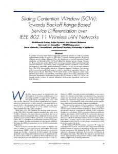
Scenario-1 includes a chain of three stations with two flows. The coordinates of stations are shown in Fig. 1. This topology is also known as Large-EIFS problem [14], which is described in Fig. 2. In this scenario, stations S1 and S2 are in one transmission range. Stations S1 and R are also in another transmission range. Stations S2 and R are out of transmission range but in carrier-sensing range. At the last state of four-way handshaking process from sender S1 to receiver R, R sends an ACK frame in reply to a data frame from S1, then S2 detects the ACK frame, but cannot decode it. Thus, S2 must wait an EIFS before accessing the channel, while S1 waits a DIFS, which is much smaller than the EIFS. Li et al. [14] has proved that allocated bandwidth for S1 is four times greater than S2 because of the Large-EIFS problem. (400,0)
(200,0)
(0,0)
S2
S1
R Flow 1 Y-Axis
Flow 2 X-Axis
Fig. 1. Scenario-2: The Large-EIFS problem.
EIFS S2
S1
R
EIFS
NAV (RTS)
DIFS
SIFS
RTS
SIFS
CTS
DIFS
DATA
SIFS
ACK
DIFS
Back-off
Back-off
Back-off
Fig. 2. Unfairness in bandwidth due to Large-EIFS problem.
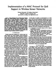
We examine network performances in this scenario by letting the stations S1 and S2 generate traffic at the same offered load G to R. The performance metrics are evaluated versus offered load G. Fairness indices are shown in Fig. 3(a). When the offered load is small, all scheduling methods get perfect fairness index. When the offered load becomes larger, because a common queue is used in FIFO scheduling, the direct flow gradually occupies completely the buffer space then the fairness index becomes very bad. In Shagdar’s method [5], even different queue is used for each flow, but the throughput of the forwarding flow is limited by the allocated bandwidth
1.6
1 0.95
1.4
FIFO scheduling
0.85
Shagdar's method
0.8
PCRQ scheduling
0.75
Proposed scheme
Throughput [Mbps]
Fairness index
0.9
0.7 0.65 0.6 0.55
1.2 1
FIFO scheduling 0.8
Shagdar's method PCRQ scheduling
0.6
Proposed scheme 0.4 0.2
0.5 0
0.2
0.4
0.6
0.8
1
1.2
Offered load G [Mbps]
1.4
1.6
1.8
2
0 0
0.2
0.4
0.6
0.8
1
1.2
1.4
1.6
1.8
2
Offered load G [Mbps]
(a) Fairness index (b) Total throughput Fig. 3. Simulation results in Scenario-1
of S2 which is too much smaller due to Large-EIFS problem [14]. Thus, the fairness index in Shagdar’s method is not good. In PCRQ scheduling [8], input and output packets to RR queues is monitored, the per-flow throughput becomes fairer and also the allocated bandwidth at the MAC layer is improved indirectly. Thus, PCRQ scheduling achieves good fairness index. In the proposed scheme, both the MAC and link layers fairness are considered, we also achieve very good fairness index. The total throughputs of all flows are shown in Fig. 3(b). When the offered load is small, throughputs in all method are similar. When the offered load becomes greater, PCRQ scheduling uses bandwidth slightly less efficiently than the others do. Because PCRQ scheduling makes a delay for sending to give chance for receiving in order to achieve the MAC layer fairness indirectly. In the proposed scheme, S2 increase its channel access frequency to get the MAC layer fairness. It also improves network utilization and the proposed scheme achieves better throughput than PCRQ scheduling. 4.2
Scenario-2
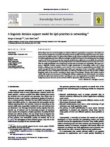
Scenario-2 is three-pairs scenario. The coordinates of stations are shown in Fig. 5. In this scenario, stations S1-S2 and S2-S3 are out of transmission range but in carrier sensing range. Stations S1-S3 are out of carrier sensing range and the two external pairs S1-R1 and S3-R3 are independent from each other. Thus, two external pairs contend bandwidth with only the central pair S2-R2 while the central pair contends with both external pairs. In this topology, the central pair cannot access the medium in saturated state. We examine fairness problem in this topology by letting the stations S1, S2 and S3 generate traffic at the same offered load G to R1, R2 and R3, respectively. The performance metrics are evaluated versus offered load G. Fairness indices are shown in Fig. 5(a). When the offered load is small, all scheduling methods get perfect fairness index. When the offered load becomes larger, FIFO scheduling does not help the central pair to access the medium. However, both PCRQ scheduling and Shagdar’s method also do not have better results than FIFO scheduling. The reasons are explained as follows. PCRQ scheduling only works in the link layer, it does not have information of flows out of transmission range. Therefore, it cannot improve the MAC layer fairness. Shagdar’s method works in both the MAC and link layers. It modifies back-off algorithm in order to achieve per-flow fairness and network utilization. However, Shagdar’s method cannot ensure the MAC layer fairness and it fails to achieve
(600,200)
(300,200)
(0,200)
R3
R2
R1 Flow 1
Flow 2
Flow 3
S2
S1
(600,0)
(300,0)
(0,0)
Y-Axis
S3
X-Axis
Fig. 4. Scenario-2: three pairs scenario. 3
1 0.9
Throughput [Mbps]
Fairness index
2.5
0.8 0.7 0.6
FIFO scheduling
0.5
Shagdar's method 0.4
PCRQ scheduling Proposed scheme
0.3
0.2
0.4
0.6
0.8
1
1.2
Offered load G [Mbps]
1.4
1.6
1.8
1.5
FIFO scheduling 1
Shagdar's method PCRQ scheduling
0.5
0.2 0
2
2
Proposed scheme
0 0
0.2
0.4
0.6
0.8
1
1.2
1.4
1.6
1.8
2
Offered load [Mbps]
(a) Fairness index (b) Total throughput Fig. 5. Simulation results in Scenario-2
per-flow fairness in this topology. In the proposed scheme, the central pair finds out that it gets less bandwidth than its fair allocated bandwidth. It will improve the channel access frequency by reducing its back-off time. Thus, the proposed scheme can achieve the good MAC layer fairness and per-flow fairness. The total throughputs of all flows are shown in Fig. 5(b). When the offered load is small, throughputs in all method are similar. When the offered load becomes greater, the proposed scheme achieves total throughput smaller than the other methods as the trade-off between fairness and throughput. In the other methods, the central pair cannot access the channel bandwidth and two external pairs can use maximum channel bandwidth. The total throughput can be twice of maximum channel bandwidth. In the proposed scheme, the MAC layer fairness is ensured, the central pair can achieve a half of maximum channel bandwidth. It leads two external pairs also can use a half of maximum channel bandwidth. Thus, the total throughput is only one and a half of maximum channel bandwidth. It is obviously smaller than in the other methods. 4.3
Scenario-3
Scenario-3 includes a chain of five stations with four flows. The coordinates of stations are shown in Fig. 6. The stations S1, S2, S3, and S4 generate traffic at the same offered load G to R. The performance results are shown in Fig. 7(a) and 7(b). The results show that both PCRQ scheduling and the proposed scheme get better fairness performance than the others. The proposed scheme also have advantage in throughput performance by comparing with PCRQ scheduling.
(800,0)
(600,0)
(400,0)
(200,0)
(0,0)
S4
S3
S2
S1
R Flow 1
Flow 2 Y-Axis
Flow 3 Flow 4 X-Axis
1
1.6
0.9
1.4
Throughput [Mbps]
Fairness index
Fig. 6. Scenario-3: a five-station chain with four flows.
0.8 0.7
FIFO scheduling
0.6
Shagdar's method 0.5
PCRQ scheduling Proposed scheme
0.4 0.3
1.2 1
FIFO scheduling Shagdar's method
0.8
PCRQ scheduling 0.6
Proposed scheme 0.4 0.2
0.2 0
0.2
0.4
0.6
0.8
1
1.2
1.4
1.6
1.8
0
2
0
0.2
0.4
0.6
Offered load G [Mbps]
0.8
1
1.2
1.4
1.6
1.8
2
Offered load [Mbps]
(a) Fairness index (b) Total throughput Fig. 7. Simulation results in Scenario-3
4.4
Scenario-4
S4
(300,0)
S2
(0,400)
(300,200)
S1
(0,200)
(300,400)
S3
(0,0)
(600,400)
S6
R1
(600,200)
S5
R2
X-Axis
Fig. 8. Scenario-4: Grid scenario.
Y-Axis
R3
(600,0)
Scenario-4 is a grid scenario with high station density and high traffic density as in Fig. 8. In this scenario, the columns are separated by distance greater than the transmission range but smaller than the carrier sensing range. The stations in a column generate traffic at the same offered load G to the receiver in the same column. This topology faces both Large-EIFS and Three-pairs unfairness problems at the MAC layer.
1 0.9
FIFO scheduling
Shagdar's method
PCRQ scheduling
Proposed scheme
3
Throughput [Mbps]
Fairness index
2.5
0.8 0.7 0.6 0.5 0.4
2
FIFO scheduling
1.5
Shagdar's method PCRQ scheduling
1
Proposed scheme 0.5
0.3 0.2 0
0.2
0.4
0.6
0.8
1
1.2
Offered load G [Mbps]
1.4
1.6
1.8
2
0 0
0.2
0.4
0.6
0.8
1
1.2
1.4
1.6
1.8
2
Offered load [Mbps]
(a) Fairness index (b) Total throughput Fig. 9. Simulation results in Scenario-4
The fairness between six flows are shown in Fig. 9(a). At the high offered load, each method achieves different fairness level due to contention between the forwarding flow and direct flow at the link layer, Large-EIFS and Three-pairs problems at the MAC layer. The fairness index of FIFO scheduling is the worst because of both unfairness problems in the MAC and link layers. Shargdar’s method achieves fairness better than FIFO scheduling due to using RR queue. However, it still faces the MAC layer unfairness problem. PCRQ scheduling can solve the unfairness in the link layer and Large-EIFS problems at the MAC layer. Our proposed method can improve fairness both at the MAC and link layers. Therefore, we achieve the best fairness in all methods. The total throughputs of all flows are shown in Fig. 9(b). At the high offered load, the proposed scheme achieves total throughput is smaller than the other methods as the same reason with Scenario-2.
5
Conclusion
Our proposed scheme is divided in two parts. One works on the MAC layer. We slightly modified back-off algorithm in order to achieve fair allocated bandwidth for each station. The other works on the link layer. We controlled RR queue in order to help each flow use bandwidth fairly. The cross-layer signal is sent from the link layer to the MAC layer to required the MAC layer sends the packet from the heavy offered load flow with longer back off time. The parameter γ can be chosen any value from zero to one and the parameter κ can be chosen any value greater than one. The same reason with PCRQ scheduling, the large value of these parameters may degrade bandwidth utilization. In our simulations, we chose γ equal to 0.3 and κ equal to 2. In the simulation results, we evaluate our method by comparing with some other methods. The results showed that our method achieved good performances in Large-EIFS problem, three-pairs problem scenarios and also complex topologies as long-station chain and grid scenarios. In these topologies, FIFO scheduling has only one queue, and then it cannot solve the link layer contention. Shagdar’s method uses RR queue, but also works ineffectively because the allocated bandwidths at the MAC layer are not suitable for forwarding and direct flows in the link layer. PCRQ scheduling can achieve good per-flow fairness. However, it fails to keep good per-flow fairness of flows, which do not come to the link layer. The proposed scheme works in both the MAC and link layers for aiming to improve both the MAC and link layer fairness. Therefore, we have good results in per-flow fairness even in the MAC layer unfairness topologies. Moreover, the
proposed scheme gets better throughput performance than PCRQ scheduling compared to link layer topologies as Large-EIFS and long-station chain topologies. Because PCRQ scheduling tries to get the MAC layer fairness indirectly by giving a delay of heavy offered load flow to give a chance for forwarding flows. It affects to throughput performance. The proposed scheme adjusts back-off time to let disadvantaged station can get better channel bandwidth. Therefore, throughput performance in the proposed scheme also improves. In the MAC layer unfairness topologies, fairness between stations is improved by our method then total throughput is reduced as the trade-off between fairness and throughput.
References 1. Department, I.S.: IEEE 802.11 wireless lan medium access control (MAC) and physical layer (PHY) specifications. ANSI/IEEE Standard 802.11 (1999) 2. Xu, S., Saadawi, T.: Does the ieee 802.11 mac protocol work well in multihop wireless ad hoc networks? Communications Magazine, IEEE 39(6) (2001) 130–137 3. He, J., Pung, H.K.: One/zero fairness problem of MAC protocols in multi-hop ad hoc networks and its solution. Proceedings of the International Conference on Wireless Networks (2003) 479–485 4. Jangeun, J., Sichitiu, M.: Fairness and qos in multihop wireless networks. IEEE Vehicular Technology Conference 5 (2003) 2936–2940 5. Shagdar, O., Nakagawa, K., Zhang, B.: Achieving per-flow fairness in wireless ad hoc networks. Elec. Comm. in Japan, Part 1 89(8) (2006) 37–49 6. Izumikawa, H., Sugiyama, K., Matsumoto, S.: Scheduling algorithm for fairness improvement among subscribers in multihop wireless networks. Elec. Comm. in Japan, Part 1 90(4) (2007) 11–22 7. : The Network Simulator: ns-2. http://www.isi.edu/nsnam/ns/ 8. Giang, P.T., Nakagawa, K.: Scheduling algorithms for performance and fairness over 802.11 multi-hop wireless ad hoc networks. In: IEICE Tech. Rep. NS2008-21 (June 2008) 19–24 9. Karn, P.: Maca: A new channel access method for packet radio. In: ARRL/CRRL Amateur Radio 9th computer Networking Conference. (1990) 134–140 10. Bharghavan, V., Demers, A., Shenker, S., Zhang, L.: MACAW: a media access protocol for wireless lan’s. In: Proceedings of the conference on Communications architectures, protocols and applications, ACM (1994) 212–225 11. Nandagopal, T., Kim, T.E., Gao, X., Bharghavan, V.: Achieving mac layer fairness in wireless packet networks. In: Proceedings of the 6th annual international conference on Mobile computing and networking, ACM (2000) 87–98 12. Bensaou, B., Wang, Y., Ko, C.C.: Fair medium access in 802.11 based wireless ad-hoc networks. In: Proceedings of the 1st ACM international symposium on Mobile ad hoc networking & computing, IEEE Press (2000) 99–106 13. Jiang, L.B., Liew, S.C.: Improving throughput and fairness by reducing exposed and hidden nodes in 802.11 networks. IEEE Transactions on Mobile Computing 7(1) (2008) 34–49 14. Li, Z., Nandi, S., Gupta, A.K.: Ecs: An enhanced carrier sensing mechanism for wireless ad-hoc networks. Computer Communication 28(17) (2005) 1970–1984 15. R.Jain, Chiu, D.M., Hawe, W.: A quantitative measure of fairness and discrimination for resource allocation in shared conputer systems. Technical Report TR-301, DEC Research Report (1984)