Contextual Prototyping of User Interfaces Chris Stary University of Linz Department of Business Information Systems, Communications Engineering Freistädterstraße 315, A-4040 Linz, Austria fax: +43 732 2468 7111, tel: +43 732 2468 7102
email:
[email protected], URL: http://www.ce.uni-linz.ac.at/research/TADEUS based approaches for contextual design and prototyping, it turns out that traditional approaches, e.g. [4], support different perspectives on development knowledge, but tend not to model how a system might be used by users in accomplishing their work tasks. These approaches rather attempt to provide designers with structured facilities for engineering user interface software, e.g., [11,15]. They lack structured representation of context (tasks, users or work processes) as well as mechanisms to transform that knowledge to code. Contextual development, however, requires both. Developments in the field of task-based design, such as ADEPT [8] and MUSE [10], based on experiences with cognitive engineering approaches, such as GOMS [7], enable the representation of context information. Their prime concern is to improve design by enhancing its suitability for end user tasks, thus implementing the principles of user-centered design [12]. Task-based techniques also focus on the process of creating design solutions from information about the user's tasks, increasing confidence that the system is compatible with the tasks it is intended to support. Model-based and taskbased approaches have several features in common [21], such as: 1. They both focus on the use of models to represent the various sorts of information that contribute to the design of interactive systems. 2. Both approaches discuss issues pertaining to the use of the models in design activities (e.g., analysis, evaluation, generation, verification etc.). Due to their openness model- and task-based approaches are candidates to capture the context of user interfaces comprehensively and derive context-sensitive design solutions. The latter requires a minimal reduction of semantics along the development process, i.e. seamless development, whereas capturing the context requires high expressivity in terms of language and tools [11]. In the following we demonstrate the benefits of combining model-driven and task-based development when reporting on the TADEUS (Task Analysis/Design/End User Systems) project. Its seamless methodology and the corresponding development support allow for contextual specification and prototyping. We detail the steps to be followed throughout design based on different perspectives (models), the ontology and diagrammatic (re)pre-sentation scheme for specification, and implementation issues. We conclude discussing related work, achievements, and future research activities.
ABSTRACT
Contextual development differs from traditional user interface development in several ways: It focuses on the context of usage and the user population rather than on the technical features required for interaction. However, the latter come into play when transforming context specifications into user-interface code. Contextual development also considers design to be a non-linear process based on activities (re)engineering work processes rather than performing traditional software-engineering tasks. Consequently, contextual development requires usage-relevant (re)presentation and execution mechanisms. Although the specification of task- and user-knowledge has been recognized to be crucial for contextual user interface design, seamless development support is still lacking. The reported TADEUS (Task Analysis/Design/End User Systems) project targets toward an environment that allows contextual and seamless design and prototyping based on user and task knowledge. Due to its model-based nature TADEUS is open with respect to diagrammatic notations for specification, and different interaction platforms. As a result, different perspectives on the context, development process and its results can be kept consistent throughout development. Keywords
Contextual design, seamless development, prototyping, tools, user-centered system design, usability engineering, lifecycle management, object-oriented modeling, interactive work design, customization, model-based development INTRODUCTION
Contextual development has been recognized to be crucial for meeting the demands of user-centred systems design, e.g., [16]. Not only particular methods have been proposed, e.g. [2], but also approaches to standardize methodologies, e.g., ISO DIS 13407. However, seamless development support is still lacking. For instance, when considering model-
Permission to make digital or hard copies of all or part of this work for personal or classroom use is granted without fee provided that copies are not made or distributed for profit or commercial advantage and that copies bear this notice and the full citation on the first page. To copy otherwise, or republish, to post on servers or to redistribute to lists, requires prior specific permission and/or a fee. DIS ’00, Brooklyn, New York. Copyright 2000 ACM 1-58113-219-0/00/0008…$5.00.
388
of work. The user model details the individual perception of tasks, data structures and interaction devices, as well as task/role-specific access modalities and permits to data. The (problem domain) data model provides the static and dynamic specification of the data-related functionality. It has to be derived from the task model. The interaction model captures all devices and styles that might be used by the users in the course of interaction. The final specification is an application model. It integrates and synchronies structure and behavior specifications.
CONTEXTUAL DEVELOPMENT USING TADEUS
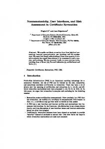
The understanding of end users and their organization of work requires a conceptual framework of context-sensitive components of interactive systems. The TADEUS framework puts the following components into mutual context [19]: task model, user model, (problem domain) data model, and interaction (domain) model. For the sake of context-sensitivity all of them have to be related mutually, statically and dynamically (see also Figure 1). The task model comprises the decomposition of user tasks according to the economic and the social organization
relate to refine to
Task Model
Business Intelligence Model
Problem Domain Data Model refine to
User Model
relate to
relate to Interaction Domain Model
refine to Application Model TADEUS-based development
user interface prototype Figure 1: The TADEUS Model-Based Frame of Reference
mouse buttons). User models become important components of human-computer interfaces, as soon as it is recognized that a software system will be able to exhibit user-oriented behavior only if it has access to a user model that holds information about users’ characteristics regarding certain tasks being performed, as well as the styles and media used for interaction. (Problem Domain) Data Modeling: Specification of a semantic data model derived from the tasks and user organization in the problem domain. In contrast to traditional data modeling, in TADEUS both aspects of the data required for task accomplishment, are captured, namely, the static and the dynamic properties. Interaction Modeling: Setting up an interaction model is mostly based on a generic user interface architecture. It should take into account devices, media, and modalities that are initially considered to be relevant for task accomplishment and user support. A device/widget model is derived from the generic architecture. This way, a common look and feel but still platform-conform solution for the application under development can be specified. Application Modeling: Final integration of the models, namely the task, user, data and interaction model, through mutually tuning them from a static and dynamic perspective. This way, the architecture and behavior of the becomes taskcomplete, in the sense that each task that requires interaction support has been assigned to or has become part of a dialog.
For contextual prototyping, basically three steps have to be performed: 1. Task analysis, resulting in a business intelligence model 2. Task-based design, resulting in an application model (based on the aforementioned models) 3. Workflow-driven prototyping, i.e. executing the specification of an application model. The analysis of work (step 1) is performed using TATAR (TADEUS Task Analysis and Representation technique) [20] which leads to a business intelligence model, i.e. a specification of user and task settings. This model serves as the basis for the subsequent design activities (step 2) that are described below. Task modeling: Specification of a task model relevant for user interface design according to the organization of tasks and users’ perception of work, usually being a part of the business intelligence representation. Task modeling includes modeling of the objectives users want or have to meet, probably in response to particular situations or events, as well as modeling of the different activities that users have to perform to accomplish their tasks, as, e.g., given by global and local business processes. User modeling: Setting up a role model by defining specific views on tasks and data (according to the functional roles of users), as well as individual user characteristics or particular features for user-adapted interaction, such as required left-hand assignments to interaction media (e.g., 389
they turned out of being used in several TADEUS case studies. The set up of a business specification requires basic relationships, such as ‘employs’ or ‘has’. The first relationship enables to assign functional roles to the identified organization, whereas the second one enables the specification of properties (attributes) to any node, such as ‘social security number’ to ‘employee’. Refinement and abstraction are performed using the common generalization/specialization and aggregation relationships, namely ‘is a’ and ‘has part’, respectively. Relating, the third type of development activity when using TADEUS, however, means setting those relationships that constitute intelligence specific to an organization. The listed set of relationships comprises relationships between conceptual entities of the same and different models. It is the latter part where TADEUS differs from other contextual specification techniques, namely the provision of dedicated relationships to prohibit design knowledge to fall apart for the sake of software component specification. To make that work, each of those relationships is checked through particular algorithms according to its semantics when being used for specification. Because of these operational definitions, the consistency of component specifications with the semantics of the application and its context can be preserved along the different phases of development.
The activities described in step 2 do not have to be performed in a linear way, except modeling the business intelligence and deriving a task model, in order to have a welldefined starting point for design. We observed design to be based on switching between views (i.e. models). For instance, as soon as a designer recognizes that some users require a mouse for interaction, he/she selects the relevant interaction elements from a platform specification in the interaction model. Then, he/she switches (back) to the user model and proceeds with detailing roles. Finally, in step 3 a prototype can be generated directly from the specification, namely from the application model. Figure 1 displays the mentioned models and elementary activities of developers (relate to, refine to) when using TADEUS. KNOWLEDGE REPRESENTATION AND PRESENTATION
The following conceptual entities are used to both capture the knowledge acquired through analysis, and to proceed with the design of task-based and user-centered interaction features in a seamless way: The organization and/or organizational units are required to provide a framework for the representation of organizational intelligence. They might represent the set of departments the organization is composed of, or vertically and/or horizontally placed structures, such as hierarchical layers within organizations. Roles are required to achieve a comprehensive representation of the organizational setting, and to model end users. Together with the activities and the materials that are processed in the course of task accomplishment, roles represent a part of the organizational intelligence that is required to run business processes. Activities are all actions that might be performed by instances of roles or machines, as they occur in the course of task accomplishment. They are part of tasks or sub tasks. They might also depend on mutual temporal and causal constraints, thus being part of the workflow to be supported. Materials can either be data or physical objects that have to be processed in order to accomplish a task. Usually, they are assigned to activities and manipulated in the course of task accomplishment, finally representing the results of work processes. Events are those points of reference that might have to be considered as being particular for the business to be supported. Events might lead to specific procedures, such as handling emergency cases. Events might also be described at several levels of detail, in order to understand the consequences when particular situations occur. Table 1 shows the types of links representing conceptual relationships between the entities listed above, as detailed in [20]. They do not only support the structural perspective on a business, but also the dynamic one. In particular, the flow of work, i.e. how things are getting done, is modeled at that layer of abstraction. In addition, particular relationships may be composed of existing ones, in case the provided ones do not suffice in accuracy or in semantics. In the table the links are categorized according to their type of activity in the course of analyzing and designing user interfaces, as
SET UP
REFINE & RELATE ABSTRACT
EMPLOYS HAS
IS A HAS PART
HANDLES, CREATES, CONCERNS, INFORMS, CONTROLS, REQUIRES, BEFORE, IS BASED ON, CORRESPONDS TO, IS ATTACHED TO
Table 1: Semantic Relationships in the Context of Development Activities The operational definitions enable seamless development, since parts of the business intelligence model can be directly mapped to the task, user, or data model, when using the listed conceptual entities and relationships. Seamless development is also supported at the level of presentation. In TADEUS a diagrammatic notation is used, as requested for object-oriented modeling ([9], p. 127) when being used beyond software specification: “... using a higher level language whose model for persistent objects and behavior protocols is precisely the same model used for analysis, specification, and design.” Hence, contextual development is work system development, and requires “more inclusive” (Ibid.) representation and presentation schemes than traditional software development. The diagrams used for presentation are supported by most of the object-oriented software development techniques, such as OSA [3] and UML [5]: • ORDs (Object-Relationship Diagrams) describing the structural relationships between classes or objects • OBDs (Object-Behavior Diagrams) describing the behavior (dynamics) of objects
390
•
cally rich representation of the context. Based on this speci fication of knowledge the initial designer’s task of step 2 of the TADEUS methodology is to set up a task complementary specifications according to the users’ roles model that captures all those relevant parts from the business intelligence model that are considered to be relevant until the specification of the structure and behavior of the application model enables prototyping.
OIDs (Object-Interaction Diagrams) describing the interaction between life cycles of objects (specified through OBDs). These types of diagrams enriched with highly expressive elements (see above) allow for effective integration of context information with user interface specifications, as well as for transforming environment knowledge to code. This way, the shift of object-oriented specification techniques from conceptual software-specification support [1] towards systems engineering support [14] can be achieved, as requested for contextual development support ([2], p. 222).
Task Context Specification. Based on the business intelligence model those tasks that are expected to be supported through interactive software are selected. These tasks are refined and related to each other, according to the sequence of accomplishment in an Object Relationship Diagram ORD. The tasks are represented as classes (containing identifiers and descriptions, but no methods and attributes) or objects. The structural and behavior relationships are represented as links between the classes/objects. For instance, the global task human resource management might be decomposed like shown in Figure 2 (rectangles denote classes, inks relationships – triangles correspond to specializations, black triangles to aggregations). In case, the analysis leads to a representation of sufficient granularity the task model can directly be extracted from the business intelligence model (as in the sample case). This specification is the starting point for further refinement and the assignment to interaction elements, leading to instances of application specifications, such as shown in Figure 3 for recruitment support. It has been generated using the TADEUS prototyping engine.
SPECIFICATION AND PROTOTYPING The diagrammatic (re)presentation has not only been chosen for the sake of communicating development ideas, user participation, and traceability of the design process, but also to enable workflow-oriented prototyping. This way, a better understanding of the context and system requirements can be achieved. In addition, it can be demonstrated what is actually feasible with existing technologies. As we have seen, the ontology used for knowledge representation empowers the analyst and the designer with a semantically rich representation of the context. Based on this specification of knowledge the initial designer’s task of step 2 of the TADEUS methodology is to set up a task model that captures all those relevant parts from the business intelligence model that are considered to be relevant for interactive computer support. Then, refinements and preferences, problem domain data processing requirements, and interface architecture have to be performed, a semantic-
Figure 2: A Sample Business Intelligence Model
391
For each sub task at the end of an aggregation line of a global task, the procedure to be followed for task accomplishment, including the input/output-behavior has to be defined. As a consequence, the ORD of the static task model is related to a set of Object Behavior Diagrams (OBDs), each corresponding to the accomplishment of a sub task. For instance, in Figure 4 the OBD for candidate search is displayed (the rounded rectangles denote states, the links transitions). The dummy „do nothing“-transition has to be used for the sake of consistency. Figure 4: A Dynamic Task Model User Context Specification. The static user model comprises user group definitions as the organization of tasks requires. There are two ways to define user groups from the perspective of an organization, namely the functional and the individual perspective. For instance, each department of the organization at hand has a particular set of privileges, such as the right to manipulate salary data in case of human resource management (functional perspective). Each staff member has also a user profile based on individual skills and preferences, such as accounting and the use of button bars instead of menus. In TADEUS the integration of both perspectives is performed at the level of ORDs. It propagates to the concerned data (in the problem domain data model) and dialog elements (in the interaction model), and finally, to the application model.
For instance, an employee might be involved in tasks that are processed by several departments, such as an accountant doing human resource management as well as sales calculations. Hence, from the task perspective, the dynamic user model is a synchronized combination of task model OBDs under the umbrella of a particular user role. The specification has to show the task-relevant, synchronized involvement of a particular end user group in one or more subtasks. In TADEUS this step does not require additional OBDs, but might require synchronization of existing OBDs. Setting synchronization relationships is supported through OIDs. Using them, mutually dependent transitions of the involved OBDs are simply connected by dragging visual relationships denoting the passing of flow control – see for instance Figure 6. Deriving Problem Domain Data. The designer has to define the classes of data required for task accomplish1ment. Identifiers, attributes, operations and relationships have to be provided. For instance, handling human resource applications requires to create an object of the class ‘person’. Setting up a data model is also required, in order to provide information for the integration of the datarelated functionality with the interaction facilities later on (such as assigning input fields to data that are expected to be entered by the user). In order to ensure the integrity and completeness with respect to the tasks that are going to be supported, the elements of the static data model have to be put into the context of the task elements of the static task model (ORD). This step is achieved through setting the ‘is based on’ relationship between (sub) tasks and data specifications. For instance, the task ‘search for candidates’ ‘is based on’ ‘person’. Additionally, the relationships to the user model have to be completed. It has to be checked whether the access permits given through the role specification in the user model fit to the specified data model elements, and vice versa, whether each of the data classes has been actually assigned to at least one functional role specified in the user model. The behavior of the problem domain data has to be specified. For instance, the life cycle of ‘person’ has to be defined, according to the attributes and methods specified in the class ‘person’. In case of multiple involvement of a data element in several tasks, such as ‘person’ in handling human resource applications and updating staff data, the
Figure 3: A Sample Browser Window Prototype Coupling the user context with the task context requires the use of ‘handles’-relationships. Since TADEUS displays specifications in a single workspace according to the model-related view concept, the relationships can be set in an effective and efficient way. The dynamic user model captures the work process from the perspective of a particular role.
392 388
dynamic specification integrates different behavior specifications in a single representation capturing all possible states of that data element. Finally, the life cycle has to be synchronized with one or more OBDs of the dynamic task model, since each of the transitions concerning data has to be performed in conformance to at least the tasks specified in the task model. The results of this synchronization are again OIDs.
user roles, and data specified. The results of this synchronization process are again OIDs. This way it becomes evident, which of the interaction elements have to be manipulated to accomplish each of the tasks (including the manipulation of data). For instance, by the time personnel data have to be inserted, the OBD for name field has to be synchronized with an input field – see Figure 6 (JF = Jump Forward, JB = Jump Backward).
Assigning Interactions. The first step in interaction modeling concerns the set up of generic interaction features. In case of platform-specific solutions (e.g., for GUIs) the structure of the elements and styles has to be loaded from resource scripts. In assigning tasks and user actions to presentation elements a platform-dependent design might, in particular for GUI development, save time and effort for specification. The second step in interaction modeling concerns the static refinement and adjustment of generic interaction features, such as window management. In particular, platform-specific structures have to be adjusted to particular constellations of the elements and styles, since they provide a variety of arrangements (e.g., through recursive structures, such as container objects). Before the tasks and the problem domain data are assigned to the selection and grouping of the interaction elements and styles, in this step traditionally the fundamental look and feel of the interactive application (for GUIs) is specified. The third step in interaction modeling can be considered to be the first move towards application-specific design. The selected and pre-arranged interaction elements are further refined and tuned with other application elements, in order to achieve fully customized interaction features. Platform-specific elements and styles are adjusted to particular constellations of task-, user-, and data-specific controls and screen structures. This step leads to object definitions at an abstract level, since these design elements are in a sense unique for the application. For instance, it is specified at this stage of development that the ‘human resource management’ menu contains the entries ‘recruitment’, ‘update staff member’, ‘remove staff member’. The result is a structural specification (i.e. ORD) of the user-interface features that have been specified in the context of the task, user, and data model. The relationships used for assigning interaction elements to task and data elements are TADEUS-specific ones, such as ‘is attached to’, as well as commonly used ones for object-oriented specification, such as ‘has part’ and ‘is a’. Typically, application elements are added as subclasses to dialog classes, such as groupboxes in case of GUI platforms (see Figure 5 for Microsoft MFC). For each of the elements of the customized interaction ORD, an OBD has to be created to specify the task- and user conform interaction. For instance, the life cycle of a form has to be defined, according to the attributes and methods specified in the class ‘form’. The life cycle has to be synchronized with one or more OBDs of the other models, since each of the transitions concerning interaction elements has to be performed in conformance to the tasks,
Completing the Specification for Prototyping. Contextual, in the sense of task-complete application design requires the synchronization of the previously specified activities involved in task accomplishment. This requirement is met through providing synchronization points between states and transitions that are required to accomplish tasks successfully with the specified user interface architecture. OIDs enable the diagrammatic specification of the global behavior of the application according to the business processes to be supported at various levels.
Figure 5: Refining Generic Interaction Elements in the Structural Interaction Model
Figure 6: Relating OBDs for Task-Conform Interaction Additional (global) conditions can also be specified through OIDs linking OBDs. In setting up an application model this way, several issues are considered to be crucial: • Which key events, eventually triggered by users, lead to interactions with the software system? • All interaction-relevant tasks, actions (i.e. operations on data elements), and data have to be linked to or be a 393 389
•
instances or other steps that may influence the conditions. In Figure 7 the screenshot is given for tracing the flow of control. It shows an additional form of presentation of OIDs. A color scheme has been developed to provide a comprehensive picture of possible and executed paths. This dense but accurate presentation supports the navigation in design knowledge when executing instances of interface objects.
part of the interaction model, since they have to be presented to end users. Every possible interaction between interaction elements should be traceable, in order to avoid side effects in behavior.
Prototyping. Prototyping is enabled in TADEUS based on the application model, and thus, can be performed before the functional specification (of methods) is provided. The TADEUS interpreter and consistency checker, both required for contextual design and prototyping, are explained below. Based on the integrated specification available through the application model the interaction window, as shown in Figure 3 for the Search for Candidates example, can be directly generated using the TADEUS user interface generator. IMPLEMENTATION ISSUES
It is important that every time a TADEUS semantic relationship is used its meaning is used as specified. This way correctness, consistency and task completeness of the design specification can be preserved. A number of algorithms checks the design representations statically and dynamically. These algorithms are stored in an extensible library and are executed whenever a relationship is used to connect two elements in an editor classes, or models in the course of design. The library provides the designer with a general basis upon which algorithms might be added, as soon as the designer feels a specific need to do so in the course of application development. The library is connected to the consistency checker, repository and generator. This way, TADEUS provides a basic library as well as an open workspace, which cannot only be reused but also expanded for novel design problems and notations. New algorithms can be added to the library either before the design or during the design process. In order to be able to execute the specification of an application model, instances of the classes or objects are required. The TADEUS generator produces an executable user interface based on the following mechanism [19]:
Figure 7: Tracing the Workflow During Prototyping RELATED WORK With respect to the specification of the application’s semantics the need for proper representation schemes has already become evident, e.g. through the work for LSI [6], a Language for the Specification of Interfaces. LSI has been intended to support user interface designers to validate interface specification early in the development process. The plan-based representation approach (i.e. goal trees) as such integrates the model-based and user-centred approach as discussed in the introduction. LSI tries to capture the user’s perspective on the interface through extensive definitions of the static semantics of an interface. In addition, LSI tries to stick to the principle of user interface processing, namely separating the presentation, dialog, and application component, in order to assess architectural designs. Unfortunately, the specification of behavior falls outside the scope of LSI, since its capabilities are focusing on the structural (static) aspects. Finally, no data on LSI have been provided with respect to its use for different modalities, such as GUIs, and its effort to capture the semantics related to that modality. The restriction of specifications to static interface elements has also to be noticed for recently introduced tools, such as MOBI-D [15]. However, the authors recognize the importance of modeling end user tasks and provide some representation facilities, as initially stated in [17]. With respect to methodology a variety of approaches can be found in [22], in order to bridge the gap between analysis, design, and prototyping. However, either the techniques lack support of proper tools to bridge the gap between analysis, design and prototyping, or the tools do not allow to proceed seamless, but still in a structured way from analysis to design and prototyping. Finally, there exist only few approaches, e.g. [18], that strive for executable specifi-
Initialize runtime system For each class do: For each instance do: Get current state of instance For each transition from this state do: Check if condition is true From all possible transitions choose the one with the highest priority Execute all actions of this transition Change into destination state Next Instance Next Class The execution is interrupted, if no further transitions can be fired. However, execution can be continued by adding new 394 390
cations. Unfortunately, these attempts do not support traceability with respect to end user tasks and roles. As such they do not meet the demand for structured and transparent userinterface development. The same statement holds for approaches that try to derive presentation details from task models, e.g. [13,16], although they provide high expressivity in describing the organization of work as well as rules for transforming that knowledge to user interface designs.
5.
CONCLUSIONS Contextual design and prototyping requires systems design rather than software design. In order to accomplish this task features from task-oriented approaches had to be integrated with those of model-based approaches. In case this integration is provided with a diagrammatic notation with high expressivity they also allow seamless development. TADEUS has been designed this way. Hence, it overcomes several limitations of current approaches that are tightly coupled with inherent representational problems. A novel representation and interpretation scheme allows in TADEUS to integrates different perspectives (including he application context) through semantically linked models. The completeness of specification with respect to the intended task support, the consistency and transparency of design, and the traceability of the development process have been increased. In addition, the specification of the entire application can be executed for prototyping purposes. One of the novelties concerns the relations between elements of the models and between the models. They are automatically checked at a high level of operational semantics with the help of a series of algorithms. In addition, the software architecture of the environment is open to embed existing specification techniques and interaction platforms. Future developments in TADEUS comprise the integration of further industrial platforms (currently we support Microsoft MFC and browsers) and modeling techniques, such as UML. Another issue concerns code generation. First attempts have turned out to be promising to provide pieces of application code and a high level specification language for the specification of the data-related functionality.
8.
6.
7.
9.
10.
11. 12. 13.
14. 15.
16.
17.
18.
19. REFERENCES 1. Bailin, S.: An Object-Oriented Requirements Specification Method, CACM 32(5), pp. 608-623, 1989. 2. Beyer, H.; Holtzblatt, K.: Contextual Design. Defining Customer-Centered Systems, Morgan Kaufmann, San Francisco, 1998. 3. Embley, D. W. ; Kurtz, B. D.; Woodfield, S. N.: Object-Oriented Systems Analysis. A Model-Driven Approach. Yourdon Press, Englewood Cliffs, NJ, 1992. 4. Foley, J.D.: History, Results and Bibliography of the User Interface Design Environment (UIDE), an Early Model-based Systems for User Interface Design and Implementation, Proc. DSV-IS’94, pp. 3-14, 1994.
20.
21.
22.
395 391
Fowler, M.; Kendall S.: UML Distilled - Applying the Standard Object Modeling Language, Addison Wesley, Reading, Massachusetts, 1997. Jacquot, J.-P.; Quesnot, D.: Early Specification of User-Interfacs: Toward a Formal Approach, Proc. ICSE’97, Boston, MA, pp. 150-160, 1997. John, B.E.; Kieras, D.E.: Using GOMS for User Interface Design and Evaluation: Which Technique?, TOCHI 3(4), pp. 287-319, 1996. Johnson, P.; Wilson, St.; Markopoulos, P.; Pycock, J.: ADEPT - Advanced Design Environments for Prototyping with Task Models, Proc. INTERCHI'93, p. 56, 1993. Liddle, St.W.; Embley, D.W.; Woodfield, S.W.: A Seamless Model for Object-Oriented Systems Development, Proc. ISOOMS’94, pp. 123-141, 1994. Lim, K.Y.; Long. J.: The MUSE Method for Usability Engineering, Cambridge University Press, Cambridge, 1994. Myers, B.: User Interface Software Tools, TO-CHI 2(1), pp. 65-103, 1995. Norman, D.; Draper (eds.): User-Centered System Design, Lawrence Erlbaum, 1986. Paterno, F.D.; Breedvelt-Schouten, I.M.; de Koning, N.M.: Deriving Presentations from Task Models, Proc. EHCI’98, 1998. Parsons, J.; Wand, Y.: Using Objects for Systems Analysis, CACM 40(12), pp. 104-112, 1997. Puerta, A.R.; Cheng, E.; Tunhow, O.; Min, J.: MOBILE: User-Centred Interface Building, Proc. CHI’99, ACM, pp. 426-33, 1999. Rodriguez, F.G.; Scapin, D.L.: Editing MAD* Task Descriptions for Specifying User Interfaces, at Both Semantic and Presentation Levels, Proc. DSV-IS’97, pp. 215-225, 1997. Rosson, M.B.; Carroll, J.M.: Integrating Task and Software Development for Object-Oriented Applications, Proc. CHI'95, pp. 377-384, 1995. Sage, M.; Johnson, Ch.: Interactors and Haggis: Executable Specifications for Interactive Systems, Proc. DSV-IS’97, pp. 101-117, 1997. Stary, Ch., Vidakis, N., Mohacsi, St., Nagelholz, M.: Workflow-Oriented Prototyping for the Development of Interactive Software, Proc. IEEE COMPSAC´97, pp. 530-535, 1997. Stary, Ch; Peschl, M.: Representation Still Matters. Cognitive Engineering and User Interface Design Representations, Behavior and Information Technology 17(6), pp. 338-360, 1998. Wilson, St., Johnson, P.: Bridging the Generation Gap: From Work Tasks to User Interface Design, Proc. CADUI'96, pp. 77-94, 1996. Wood, L. (ed.): User Interface Design. Bridging the Gap from User Requirements to Design, CRC Press, Boca Raton, FL, 1998.