Camera-based monitoring is a valuable tool for assistive envi- ronments to meet
the important ... billion by 2011, as security surveillance and remote health care
become more focused on ..... sentient computing system. IEEE Computer, 34(8), ...
Continuous Camera-based Monitoring for Assistive Environments Guanling Chen, Prabhu Govindaswamy, Nan Li, and Jie Wang Department of Computer Science, University of Massachusetts Lowell 1 University Avenue, Lowell, MA, 01854 USA
{glchen, pgovinda, nli, wang}@cs.uml.edu ABSTRACT Camera-based monitoring is a valuable tool for assistive environments to meet the important needs of those who may have physical or cognitive impairment. It is, however, particularly difficult to continuously monitor a moving subject in a large facility where many cameras are deployed. In this paper, we propose Sensor-Integrated Camera Surveillance (SICS) to address this problem. SICS uses wearable wireless sensors to locate moving subjects and automatically selects the camera covering the subject, allowing human operators to focus only on one screen to monitor an individual. To improve flexibility and reduce cost, SICS connects distributed cameras through a self-organizing wireless mesh network. To reduce bandwidth consumption, SICS leverages onboard image processing on the camera for selective transmission. To enable automated reasoning, SICS uses a knowledge base for efficient rule specification and execution. Through empirical evaluation, we found that the automatic camera handoff enabled by SICS was effective for continuous camerabased monitoring. We provide quantitative performance evaluation results in this paper and discuss potential extension to the SICS infrastructure.
1.
INTRODUCTION
Our society is in the midst of a profound demographic shift, where an increasing proportion of people are over the age of 65 [3]. More than half of the older population (54.5%) reported having at least one disability of some type [2]. It is thus important to provide intelligent technology that can assist those with physical or cognitive impairment, to improve their quality of life and to meet their important personal needs [26]. Caregivers often need to continuously monitor certain individuals, such as the patients with Alzheimer diseases and the seniors who may frequently fall to the ground. Camera-based surveillance is an ideal technology that provides most direct
and effective visual information about users’ current location and activities. The global market for video surveillance system is expected to have strong growth, reaching more than US$9 billion by 2011, as security surveillance and remote health care become more focused on communities and households [6]. It is, however, particularly difficult to provide continuous visual monitoring of individuals in a large facility where hundreds of cameras are deployed. As the monitored subject moves around, the operator has to manually figure out the current camera screen that may cover that subject and get a visual confirmation that the subject does show up on that camera. If not impossible, this is certainly a tedious and slow task for the operator given potentially hundreds of camera screens he needs to monitor and a large number of mobile users in the facility. Simply increasing the number of operators, each watching some number of cameras, will not solve the problem since they have to cooperate to track certain individuals. In this paper, we propose Sensor-Integrated Camera Surveillance (SICS), a system that allows the human operator to only watch a single screen to track one subject. The images of this screen are dynamically changed based on which camera is covering the monitored subject. The subject wears a small wireless sensor that can be localized, and the location information is used to select which camera’s images should be displayed. SICS enables automatic camera handoff, which transforms traditional surveillance model from watching a location covered by a camera to watching a moving subject covered by many cameras. One of the SICS’ design goals is flexibility. Deploying a large number of cameras often requires high installation cost due to laying out network cables for IP cameras or coax cables for CCTV (Closed-Circuit TeleVision) cameras. For example, a recent 600-camera deployment to monitor parking lots cost more than $8,500 per camera [12]. While some buildings may already have deployed Ethernet infrastructure that can be used by IP cameras, managing and configuring these wired devices often incur significant maintenance overhead. SICS connects all IP cameras through a self-organizing wireless mesh network [4], to eliminate the wiring cost (each camera only requires a power cord) and to reduce the maintenance overhead (cameras do not require special configuration). We envision that next-generation IP cameras will increasingly adopt wireless-based mesh backbone to increase deployment
flexibility, as faster 802.11 standards, such as 802.11a/g/n, becomes widely available. SICS requires the subject to be tracked voluntarily wear a small wireless sensor for localization. It is possible to integrate other indoor localization technologies with SICS, such as tags based on RFID [24], infrared [32], 802.11 [10], or UWB [1]. In an assistive environment, however, a subject may already wear a sensor that constantly monitors her vital signs [22], making SICS particularly appealing for this application. To our best knowledge, SICS is one of the first systems that combines wireless mesh for flexible camera deployment, onbaord image analysis for reduced bandwidth consumption, sensor integration for subject tracking, and knowledge based control for efficient rule specification and execution. The contributions of this paper include:
• feasibility demonstration of automatic camera handoff through an empirical implementation of the SICS architecture; • quantitative performance evaluation results of a complete SICS system; • and discussions of our SICS experiences from the application studies.
In the rest of this paper, we present methodology and system components in Section 2. We evaluate the system performance in Section 3. We discuss further challenges and related work in Section 4 and 5, and conclude with Section 6.
2.
SYSTEM DESIGN
In this section, we discuss the architectural design of the SICS system, including its hardware and software components. We start from wireless routers, followed by location detection using the wireless sensors, and finally the knowledge-based control subsystem that coordinates distributed cameras using the location detected by the wireless sensors.
2.1
Wireless mesh backbone
A key component of our system architecture is the SICS wireless router, a set of which connect with each other through their IEEE 802.11 b/g radios using a wireless mesh network routing protocol. The self-organizing mesh acts as the information backbone transferring camera images, camera control, sensor data, and sensor location. These SICS routers are strategically deployed with persistent power and typically do not move. We connect cameras and sensors to these routers through their USB interfaces. These sensors act as the gateway to the mobile sensors carried by the patients, receiving the sensor readings and location information. Note the sensor-to-sensor communication goes through a separate radio channel from the mesh backbone. Typically these small sensors support low-power radio communication protocol, such as IEEE 802.15.4 (Zigbee). The gateway sensors forward data from mobile sensors to a central control server using the 802.11 mesh network.
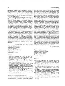
Figure 1: A SICS 802.11 wireless router with a Web camera and a 802.15.4 wireless sensor attached.
We used off-the-shelf wireless Access Points (APs), Asus WL 500g, and we reflashed them with OpenWRT,1 a tailored Linux distribution for embedded devices. We configured this device as an ad hoc wireless router, rather than an infrastructure AP, to which cameras and sensors are connected through the USB ports. We used TMote TelosB wireless sensors and simple Web cameras, such as the Philips QuickCam Zoom and Philips Pro 4000, which can be accessed through the PWC Linux driver. Figure 1 shows the SICS router with a camera and a sensor attached. An open-source software, Motion,2 is used to capture camera images and outline the image portions where motion is detected, which simply means the number of pixels that have changed between two consecutive frames exceeded a threshold. We modified Motion to transmit the camera images to the central server only when the number of image pixels changed exceeds a threshold (motion detected), to limit the bandwidth consumption of the image transmission over the wireless mesh network. While Motion also supports MPEG video sequences, we currently only use it to capture JPEG image sequences because we want to analyze the images (for motion detection) on the resource-limited routers and MPEG decoding tends to be computationally heavy. For multi-hop wireless mesh routing, we used Optimized Link State Routing (OLSR) protocol [9].3 OLSR is a proactive and table-driven ad hoc routing protocol, in which each node maintains link state information of its neighbors. The nodes exchange with each other of their own link state information periodically, thus every node has global topology knowledge to compute routing tables. As a proactive routing protocol, OLSR incurs more routing overhead than reactive protocol, such as Ad hoc On-Demand Vector routing (AODV) [25]. This is, however, not a particular concern since our mesh network is stationary and topology remains relatively stable. To reduce routing overhead, OLSR uses multi-point relay (MPR) to forward control messages, rather than flooding the whole network. 1
http://www.openwrt.org http://motion.sourceforge.net 3 http://www.olsr.org/ 2
2.2
Sensor-based localization
To select an appropriate camera that covers a moving subject, we need to determine the current location of the subject with reasonable accuracy and relatively short delay. If the localization algorithm lacks accuracy, we may end up selecting the wrong camera. If it takes a long time to obtain the localization result, the subject may have already moved to another place before we switch the camera. Indoor localization using radio signals is a challenging task because of the irregular RF propagation caused by plenty of absorbing, scattering, and multi-path effects in an indoor environment. It is thus difficult to derive a clean correlation function between the distance and the radio signal strength. Additional difficulty arises given that the relatively short distance between RF transmitters and receivers demands highly accurate clocks for multi-lateration based localization algorithms. Instead, many existing solutions require a manual process to build a RF map to achieve meter-level localization accuracy [5, 14]. Namely, it is necessary to measure the RF signatures that are signal strength samples from strategically-deployed stationary beacons. The RF signatures collected at all locations are stored in a RF database. After this “training” phase, a mobile device can periodically compute its RF signature and find a closest match in the database to determine its own location. While this approach could be labor-intensive for a large facility, the RF database is only needed to be built once and the room-level localization accuracy is suitable for the purpose of SICS applications. To build a RF signature database for wireless sensors, we used MoteTrack [20]. All gateway sensors attached to stationary SICS routers act as beacon nodes that periodically broadcast BEACON messages, and the mobile sensors carried by the subject compute their RF signatures from all beacons they can hear. The original MoteTrack requires the mobile sensor be attached to a laptop that stores RF database so the location can be determined locally. On the other hand, we want the subject to carry only a sensor, rather than a heavyweight laptop, for the targeted assistive-environment applications. We modified the MoteTrack so the mobile sensor sends its RF signature to a nearby gateway sensor (a beacon) with the strongest signal strength. That gateway sensor will then forward the RF signature to the central server for location determination. MoteTrack increases the localization accuracy by broadcasting the BEACON messages on a set of frequency channels C with a set of transmission power levels P . Namely, the beacon is transmitted on all (ci , pj ) combinations, for every ci ∈ C and pj ∈ P . The BEACON messages contain the beacon identifier, the frequency channel ci , and the power level pj , so the mobile sensor can compute RF signatures appropriately. The rational behind using more frequencies and power levels is to increase “uniqueness” of the RF signatures, since RF signals tend to have different propagation characteristics on different frequency channels and have different propagation distances with different transmission power level. To ensure appropriate reception of BEACON messages by the mobile sensors and to avoid overwhelming the wireless chan-
nel, these BEACON messages should be sent with a reasonable separating interval. For example, 802.11 APs typically broadcast their BEACONs every 100ms. A mobile sensor can only listen on one frequency channel at a time, and it needs to wait long enough time to receive the BEACON messages transmitted at all power level P and then iterate through all frequency channels C. Thus it may take a while for the mobile sensor to compute a RF signature before it sends it to the server for location determination. If this delay is too long, the calculated location may be irrelevant since the subject may have moved to another place, leading to incorrect camera selection. We evaluate the tradeoff between the size of C, P and the localization accuracy in Section 3.
2.3
Knowledge-based control
By default, the Motion program on SICS routers does not send any images. The central SICS server receives mobile sensor’s RF signatures to determine its current location and select appropriate camera that covers the mobile sensor. Then the SICS server sends a control command to the Motion on the router to which that camera is attached. Motion will start capture camera images and only send them back to server if the number of changed pixels over consecutive images exceeds a predefined threshold. To reduce the image transmission overhead over the wireless mesh network, the Motion program on SICS routers divides large images into smaller pieces and send them through UDP. If some of the UDP packets are lost, the visual quality of the reconstructed images at the server degrades. The SICS server runs a knowledge base (KB) for camera selection and control. A KB describes relationship between objects as facts, and rules are used to describe how to use the data to derive more information or to take actions based on certain facts. Our KB implementation is based on CLIPS [11], in which formal logic is used so rules can be employed to automatically deduce new facts from old facts. The key benefits of a KB include automated reasoning and efficient patternbased rule execution. The SICS knowledge base contains the facts about the location of our cameras, the camera coverage, and the routers they are attached to. The KB also contains the rules regarding which camera should be selected given a mobile sensor’s x and y coordinates. Currently we simply represent camera coverage as rectangles and select cameras whose rectangles contain the sensor’s current location. If the sensor is located in an intersection of two cameras’ coverage, such as in an open hall, our rules simply select the camera that is closest to the sensor. Note that this “closest” rule may not make sense given potential obstacles, such as furniture and doors. It is, however, relatively straightforward to encode such topology information into the KB and update the rules. The overall SICS system architecture is shown in Figure 2 with all the components we describe in this Section.
3.
EVALUATION
In this section we describe our experimental setup and present evaluation results for sensor localization, wireless mesh backbone, and overall application performance.
Figure 4: Increasing the number of transmission power decreases the error distance of localization.
Figure 2: SICS architecture diagram.
3.1
Experimental setup
We deployed the SICS prototype system on the third floor of our Computer Science building. We used five routers, four cameras and nine sensors for the experiments. Five wireless sensors were powered by the router through the USB port and four other beacon sensors powered by battery were placed at the ends of the hall way. Figure 3 shows the floor plan of the experimental setup.
3.2
Evaluation of sensor localization
For sensor localization, MoteTrack uses multiple transmission power levels and frequency channels to improve localization accuracy. The time for a mobile sensor to compute a RF signature is Nc ∗ Np ∗ w, where Nc is the number of channels used, Np is the number of power levels used, and w is the waiting interval between two BEACON messages. If we use 10 frequency channels, 5 power levels, and 100ms BEACON intervals, the RF signature calculation delay is at least 5 seconds. With additional transmission delay for the signature sent to the SICS server (see next subsection), the location determination delay is too large for our continuous camera monitoring application. We clearly need to balance the tradeoff between localization accuracy and delay. We first calculated the distance errors of localization in meters (i.e. the difference between the actual location and the estimated location) against a varying number of transmission power levels. We also made sure that the mobile sensor could hear from at least 6 beacon sensors, as suggested by MoteTrack authors [20]. In our experiment, the mobile sensor received BEACON messages from all 9 beacon sensors at the center of hall way and from 7 beacon sensors at the ends of the hallway. Here we fixed the frequency channel to be 1 and varied the number of power levels from 1 to 5. Figure 4 shows that increasing the number of transmission power levels decreases the distance errors of sensor localization. It is also clear that using two transmission power levels reduced error in distance by 14% approximately, by comparing with using only a single transmission power level. Using
Figure 5: Increasing the number of frequencies decreases the distance errors of localization. 3 and 4 transmission power levels, however, reduced error distance by only 2–5% further. Thus we chose two transmission power levels for SICS system, which gives us a room-level localization accuracy and relatively shorter delay. Next we varied the number of frequencies to be used, with 2 different transmission power levels. Original MoteTrack can achieve location accuracy of 1 meter to 1.7 meters by diversifying the radio signal over 16 frequencies [20], with a relatively long localization delay. Figure 5 shows the distance errors of localization against varying number of frequency channels. From these results, we found that that using 3 or 4 frequency channels could give us distance errors of less than 4 meters, which is comparable to a single camera’s typical coverage range and thus is sufficient for automatic camera selection. Reducing the number of frequency channels used by the sensors will also limit the potential interference to other channels, such as those used by SICS 802.11 mesh network, since both 802.15.4 and 802.11 work in 2.4GHz. Having found the desired number of transmission power levels and frequency channels, we then tried to further decrease the localization errors by increasing the number of beacons being heard by the mobile sensor at any point. It is important to note that the beacons should be well spread in the space. Doing so helps us to get varying signal strengths from beacons. Hence, we used beacons powered by batteries at the ends of hallway in the experiment (Figure 3). Figure 6 shows that increasing
Figure 3: Experiment setup of routers, sensors, and cameras. the transmission range of the router’s 802.11 radio, while we changed the power levels of the sensors’ 802.15.4 radio in sensor localization.
Figure 6: Increasing the number of beacons decreases the distance errors of localization at a small ratio. the number of beacons did decrease the distance errors. This improvement, however, was not significant. We believe that a typical indoor camera network deployment, with one beacon per camera, should be sufficient for sensor localization.
3.3
Evaluation of wireless mesh
Wireless links are less reliable and a multi-hop wireless mesh network raises more concerns on data delivery performance. To reduce transmission overhead, we used UDP to send images from routers to the server. We studied the UDP packet loss rate and the packet transfer delay over a varying number of wireless hops, using the OLSR mesh routing protocol. To increase the hop counts of the wireless mesh deployed in a limited space, we reduced the transmission power level on the router. The maximum transmission power level on the SICS routers is 19 dbm. Reducing transmission power level by 3 dbm roughly reduces transmission range by half. We used additional routers (not shown in Figure 3) to create a 5-hop wireless mesh network. Note that for this experiment we reduced
To calculate the UDP packet delay from a router to the server, we synchronized the routers and the server with a local NTP (Network Time Protocol) server. Every UDP packet included a timestamp when it was sent out by the router, so the server could compute the end-to-end transfer delay by comparing the time when the packets were received with the timestamp in the packet. Similarly, packet loss was calculated by including a sequence number in each packet. At the server, we calculated the difference between the number of packets received and the packet sequence number to get packet loss ratio. In this experiment, we set a constant image transfer rate of 5 frames (images) per second on a camera-attached router, which means that Motion sent 5 frames per second to the server. Currently the camera driver on the router only allows maximum capture resolution to be 160x128. Thus each frame is split into 3 UDP packets of size 16,000 bytes and the total size of each frame is approximately 40,000 bytes. Thus 3 consecutive UDP packets can be used to reconstruct the original JPEG image, and losing one or more of these packets will degrade the image quality and overall application experience. From the Figure 7, it is clear that increased number of hops incurred more delay as expected. Note that the standard deviations of the delay were large (comparable to the mean). We believe that this was caused by the bad channel condition, instead of mainly caused by the routing protocol. The wireless condition in our building is known to be bad with overcrowded devices from research labs, department APs, and university APs. The 802.11 MAC layer will retransmit a lost packet for up to 7 times, which leads to large variations due to transient channel errors. The increased hop count and periodic flooding
is capable of locating a subject with an error of 3 meters. This is achieved by MoteTrack with 2 different transmission power levels and 4 different frequency channels. It takes almost 1 second to calculate and deliver a single location report; i.e. every second we have a location update from the MoteTrack. With the 3-meter accuracy, we can have a effective system that consists of one camera per room.
Figure 7: Increasing the number of hops increases the transmission time of the network.
The end-to-end application-level delay, time taken to locate the object until correct images received at the server, ranges from 1.1–1.8 seconds, depending on the number of hops, which is reasonable for camera handoff to follow a subject on feet. This time delay includes transmission of RF signatures to the server, RF signature matching, KB rule execution, transmission of camera control command to the router, and finally transmission of images from the router to the server. In this calculation, we mainly considered the location detection and image transmission time. We had to ignore the RF signature transmission time from the mobile sensor to the gateway sensor, since we could not appropriately synchronize the mobile sensor with the routers. Fortunately, this one-hop sensor-tosensor delay tends to be small.
Figure 8: Increasing the number of hops increases the packet loss.
Figure 9 shows three sample images received at the server. The left image is perfect without any packet loss. The image on the right is blank because of packet loss and the middle image was obtained after a small packet loss. Overall, the continuous camera-based monitoring application based on SICS is quite usable, despite of the adverse wireless channel conditions in our department building. A video demo can be downloaded from our project website http://www.cs.uml. edu/~glchen/sics/.
of routing messages will further amplify the delay variations.
4.
Figure 8 shows the packet loss rate against the increasing number of hops. Like packet delay results, we got a roughly linear curve and relatively large standard deviations. Based on these experiments, a wireless mesh network with more than 3 hops deployed in our building will unlikely be able to deliver desired application experience. This means that we need to increase the number of mesh gateways, which are the mesh routers with wired Ethernet connections, to effectively reduce the number of wireless hops.
Wireless mesh networks are designed to be self-organizing to reduce the configuration and maintenance overhead [4]. In reality, however, the fact that these networks are usually deployed in a license-free frequency band and may suffer significant interference from nearby devices. Other potential hardware and software faults include buggy firmware, routing and MAC layer protocol misbehaviors, channel congestion, and malicious attacks. Without a monitoring and management system for the mesh network itself, it is difficult to explain the network performance.
One possible improvement is to reduce the size of UDP packets, which have better chances to be delivered successfully over a bad wireless channel. This may effectively reduce the delay and its variations. In theory, however, a single radio based wireless mesh network has limited capacity due to severe self-interference [13]. Recently there has been increased interests on multi-radio multi-channel mesh networks [18]. Experimental results showed that a two-radio mesh could improve throughput up to 7 times than a singleradio system because of reduced interference between neighbors [30]. We plan to investigate this new architecture for a better-performance mesh backbone.
3.4
Overall performance of the system
Our SICS prototype has been successfully tested using the setup shown in Figure 3. Our sensor localization subsystem
DISCUSSION
Recent work on mesh management includes DAMON [29], where mesh routers periodically send their state to a central server for analysis. Mesh-Mon provides a novel monitoring solution even if the routing protocol completely fails by leveraging mobile users to ferry management packets between disconnected network partitions [23]. Qiu and others propose a simulation-based diagnosis engine that can automatically troubleshoot common mesh problems [27]. Existing work, however, has not incorporate detailed 802.11 MAC-layer information [31] for mesh monitoring and the coexistence of both wireless sensors and wireless mesh adds additional complexity for network management. We plan to investigate this research direction as future work. The sensor localization subsystem can achieve room-level accuracy in our experiments. While we expect the accuracy is
Figure 9: Sample images with three different degrees of loss. The portion of changed pixels is outlined with a rectangle. good enough for our applications, it is possible that an incorrect camera is selected due to distance errors. This may confuse human operator as the tracked subject has disappeared. It may be useful to show a couple of thumbnail images from adjacent cameras so the operator can manually click to override the automatically selected camera. Based on our experience, if the camera network does not provide an complete coverage, the operator may get uncomfortable as the subject moves to a place that is not covered. Some human interaction studies are clearly needed to balance the coverage and operator expectation. On the other hand, the occasional image loss (refreshing stopped) and packet loss (partial images) do not seem to concern the operator much. To track multiple subjects, an operator may need to open several screens, each covering an individual. Namely, images of one screen are from the camera that covering the current location of a specified subject. It is thus possible two or more screens show the same images from the same camera, if several people are gathering in the same location. To scale up the system, multiple operators can be assigned so each tracks a subset of targeted subjects. As a feature to be implemented later, we may also show the images only if some events regarding the tracked targets are detected, such as significant movement, falling to the ground, and abnormal vital signs. The all wireless design of SICS systems also introduce security issues. For example, the camera images may be easily intercepted and the wireless links can be easily disrupted [31]. Both security protocols and wireless intrusion detection systems must be used to address these issues. Privacy is another challenge in SICS-like systems where users’ location, activity, and medical information are tracked and recorded. While we envision the patients may be willing to sacrifice some privacy for better healthcare in assisted-living applications, we should provide technology for better privacy protection. For example, users should be able to understand and control how their personal information is used. Tracking may only be triggered if urgent events are detected or tracking should be stopped temporarily if the users pressed a button on the sensor. These security and privacy issues will be addressed by SICS in future.
5.
RELATED WORK
The design goals of SICS include using wireless mesh for flexible and quick deployment, using onboard image processing to reduce bandwidth consumption, and integrating wireless sensors for increased application intelligence. The combination of these components represents a new design choice for the
multi-modal sensing systems. Researchers have developed several prototypes with camera modules directly mounted on wireless sensor platforms, such as Cyclops [28] and XYZ [21]. These low-cost camera sensor systems are ideal for quick deployment in unmanageable spaces, such as the battlefield for military applications and the remote areas for habitat studies. Due to severe bandwidth constraints on the low-power radios, however, these devices typically employ lightweight onboard image processing algorithms and do not provide continuous high-resolution images. SICS connects cameras with high-speed wireless mesh network to enable better surveillance quality for the assistive environment, where IT infrastructures can be appropriately managed. Panoptes is a platform built with faster 802.11 wireless networks with a focus on low-power consumption [8] and SensEye focuses on a tiered camera system consisting of both sensor-based and backbone-based cameras [17]. Motorola wireless mesh networks support outdoor video surveillance,4 where all camera videos are processed in a central place to enable smart surveillance using video-analysis algorithms [15]. These systems and other wireless mesh for video surveillance [19], are designed to monitor general population without explicit cooperation from the monitored subjects. The proposed SICS system, on the other hand, focuses on assistive environments where subjects may have already wear sensors for location tracking and vital signs monitoring. The integration of sensors with camera surveillance can add more accurate application intelligence since existing video-analysis algorithms tend to be error prone given the potentially low-grade camera images. Currently SICS sensors are only used to track the location of moving subjects. It is, however, easy to extend the architecture to include vital signs monitoring [22] and fall detection [7]. The cooperation between cameras and sensors can significantly improve the accuracy of fall detection [33, 16] and provide immediate visual cues for these incidents.
6.
CONCLUSION WORK
AND
FUTURE
We have demonstrated the feasibility of continuous camerabased monitoring using wireless mesh backbone, onboard image processing, sensor integration, and knowledge-based con4
http://www.motorola.com/mesh/
trol. The evaluation of a prototype system shows reasonable performance on sensor localization, image transmission over a multi-hop mesh network, and overall application quality. To improve system scalability, we plan to investigate multi-radio architecture and new routing protocols for the wireless mesh backbone. We also plan to deploy SICS prototype and its applications in a real-world environment for an extended period for real users.
[17]
[18]
Acknowledgments This work is supported in part by the Research Council and Center of Network and Information Security at University of Massachusetts Lowell.
7.
REFERENCES
[1] Mike Addlesee, Rupert Curwen, Steve Hodges, Joe Newman, Pete Steggles, Andy Ward, and Andy Hopper. Implementing a sentient computing system. IEEE Computer, 34(8), August 2001. [2] A profile of older Americans: 2003. Administration on Aging, U.S. Department of Health and Human Services, 2003. [3] Population pyramid summary for United States. U.S. Census Bureau, 2007. [4] Ian F. Akyildiz, Xudong Wang, and Weilin Wang. Wireless mesh networks: A survey. Computer Networks, 47(4):445–487, March 2005. [5] Paramvir Bahl and Venkata N. Padmanabhan. RADAR: An in-building RF-based user location and tracking system. In Proceedings of the 19th Annual Joint Conference of the IEEE Computer and Communications Societies, Tel Aviv, Israel, March 2000. [6] Networking/IP to drive video surveillance market growth. iSuppli Market Analysis Report, March 2007. [7] J. Chen, K. Kwong, D. Chang, J. Luk, and R. Bajcsy. Wearable sensors for reliable fall detection. In Proceedings of the 27th Annual International Conference of the Engineering in Medicine and Biology Society, pages 3551–3554, 2005. [8] Wu chi Feng, Brian Code, Ed Kaiser, Mike Shea, Wu chang Feng, and Louis Bavoil. Panoptes: Scalable low-power video sensor networking technologies. In Proceedings of the Eleventh ACM International Conference on Multimedia, pages 562–571, Berkeley, CA, November 2003. [9] T. Clausen and P. Jacquet. Optimized link state routing protocol (OLSR). IETF RFC 3626, October 2003. [10] Ekahau realtime location system. Ekahau, Inc. [11] Joseph C. Giarratano and Gary D. Riley. Expert Systems: Principles and Programming, Fourth Edition: Principles and Programming. Course Technology, October 2004. [12] Martin Gill, Ross Little, Angela Spriggs, Jenna Allen, Javier Argomaniz, and Sam Waples. Assessing the impact of CCTV: The Hawkeye case study. Home Office Online Report, December 2005. [13] Piyush Gupta and P. R. Kumar. The capacity of wireless networks. IEEE Transactions on Information Theory, 46(2):388–404, March 2000. [14] Andreas Haeberlen, Eliot Flannery, Andrew M. Ladd, Algis Rudys, Dan S. Wallach, and Lydia E. Kavraki. Practical robust localization over large-scale 802.11 wireless networks. In Proceedings of the Tenth Annual International Conference on Mobile Computing and Networking, pages 70–84, Philadelphia, PA, September 2004. [15] A. Hampapur, L. Brown, J. Connell, S. Pankanti, A. Senior, and Y. Tian. Smart surveillance: Applications, technologies and implications. In Proceedings of the Joint Conference of the 4th International Conference on Information, Communications and Signal Processing, and the 4th Pacific Rim Conference on Multimedia, pages 1133–1138, Singapore, December 2003. [16] A. Keshavarz, A. Maleki-Tabar, and H. Aghajan. Distributed
[19]
[20]
[21]
[22]
[23]
[24] [25] [26]
[27]
[28]
[29]
[30]
[31]
[32] [33]
vision-based reasoning for smart home care. In Proceedings of the ACM SenSys Workshop on Distributed Smart Cameras, 2006. Purushottam Kulkarni, Deepak Ganesan, Prashant Shenoy, and Qifeng Lu. SensEye: A multi-tier camera sensor network. In Proceedings of the 13th Annual ACM International Conference on Multimedia, pages 229–238, Hilton, Singapore, November 2005. Pradeep Kyasanur and Nitin H. Vaidya. Capacity of multi-channel wireless networks: Impact of number of channels and interfaces. In Proceedings of the 11th Annual International Conference on Mobile Computing and Networking, pages 43–57, Cologne, Germany, August 2005. Francesco Licandro and Giovanni Schembra. Wireless mesh networks to support video surveillance: Architecture, protocol, and implementation issues. EURASIP Journal on Wireless Communications and Networking, 2007(1), January 2007. Konrad Lorincz and Matt Welsh. MoteTrack: A robust, decentralized approach to RF-based location tracking. Personal and Ubiquitous Computing, 11(6), August 2007. D. Lymberopoulos and A. Savvides. XYZ: A motion-enabled, power aware sensor node platform for distributed sensor network applications. In Proceedings of the Fourth International Symposium on Information Processing in Sensor Networks, pages 449–454, Los Angeles, CA, April 2005. David Malan, Thaddeus Fulford-Jones, Matt Welsh, and Steve Moulton. CodeBlue: An ad hoc sensor network infrastructure for emergency medical care. In Proceedings of the Workshop on Wearable and Implantable Body Sensor Networks, April 2004. Soumendra Nanda and David Kotz. Mesh-Mon: A multi-radio mesh monitoring and management system. Computer Communications, January 2008. Accepted for publication. RFID-assisted localization and communication for first responders. NIST. C. Perkins, E. Belding-Royer, and S. Das. Ad hoc on-demand distance vector (AODV) routing. IETF RFC 3561, July 2003. M. E. Pollack. Intelligent technology for an aging population: The use of AI to assist elders with cognitive impairment. AI Magazine, 26(2):9–24, 2005. Lili Qiu, Paramvir Bahl, Ananth Rao, and Lidong Zhou. Troubleshooting Wireless Mesh Networks. ACM SIGCOMM Computer Communication Review, 36(5):17–28, October 2006. Mohammad Rahimi, Rick Baer, Obimdinachi I. Iroezi, Juan C. Garcia, Jay Warrior, Deborah Estrin, and Mani Srivastava. Cyclops: In situ image sensing and interpretation in wireless sensor networks. In Proceedings of the Third ACM Conference on Embedded Networked Sensor Systems, pages 192–204, San Diego, CA, November 2005. K.N. Ramachandran, E.M. Belding-Royer, and K.C. Almeroth. DAMON: A distributed architecture for monitoring multi-hop mobile networks. In Proceedings of the 1st IEEE International Conference on Sensor and Ad Hoc Communications and Networks, pages 601–609, Santa Clara, CA, October 2004. A. Raniwala and Chiueh Tzi-cker. Architecture and algorithms for an IEEE 802.11-based multi-channel wireless mesh network. In Proceedings of the 24th Annual Joint Conference of the IEEE Computer and Communications Societies, pages 2223–2234, Miami, FL, March 2005. Yong Sheng, Guanling Chen, Keren Tan, Udayan Deshpande, Bennet Vance, Hongda Yin, Chris McDonald, Tristan Henderson, David Kotz, Andrew Campbell, and Joshua Wright. MAP: A scalable monitoring system for dependable 802.11 wireless networks. IEEE Wireless Communications, April 2008. Accepted. VISion: Enterprise locating solution. Versus Technology, Inc. Adam Williams, Deepak Ganesan, and Allen Hanson. Aging in place: Fall detection and localization in a distributed smart camera network. In Proceedings of the 15th International Conference on Multimedia, pages 892–901, Augsburg, Germany, September 2007.