VOL. 11, NO. 13, JULY 2016
ARPN Journal of Engineering and Applied Sciences
ISSN 1819-6608
©2006-2016 Asian Research Publishing Network (ARPN). All rights reserved.
www.arpnjournals.com
CONTINUOUS SIGN LANGUAGE RECOGNITION FROM TRACKING AND SHAPE FEATURES USING FIS AND ANN M. V. D. Prasad, D. Anil Kumar, P. V. V. Kishore, A. S. C. S. Sastry, A. Harini, K. Raviteja, N. Roja Sneha and B. Ashok Reddy Department of Electronics and Communications Engineering, K.L. University, Green Fields, Vaddeswaram, Guntur - DT., India E-Mail:
[email protected]
ABSTRACT Fuzzy and Neural Network based classification of continuous sign language videos with simple backgrounds trained with hybrid features is the focus of this work. Tracking and capturing hand position vectors is the artwork of horn schunck optical flow algorithm. Active contours extract shape features from sign frames in the video sequence. The two most dominant features of sign language are combined to build sign features. This feature matrix is the training vector for Fuzzy Inference Engine (FIS) and Artificail Neural Networks (ANN). The classifiers are tested with 50 signs in a video sequence. Ten different signers created 50 signs. Different instances of FIS and ANN are tested with different combination of feature vectors. The results draw comparisons between FIS and ANN classifiers for Contineous Sign Language. A word matching score (WMS) gauges the performance of the classifiers. A 90.8% average matching score is reported for FIS and 91.2% for ANN. Keywords: optical flow tracking, active contour shape analysis, continuous sign language, hybrid feature vector, fuzzy inference engine, artificial neural networks.
INTRODUCTION The field of computer vision and it’s applications is the new topic of interest to many researcher’s around the world. Drastic enhancement is up-to-the-minute in this field and one of the toughest challenges of computer vision applications is motion estimation, shape estimation and their analysis. Detecting sign language continuously in a video sequence is a complex problem in computer vision. Many works focus on static image based sign language recognition systems. These systems follow four steps: preprocessing, segmentation, feature extraction and classification. Even though most of the research has shifted to video signs, the major portion of it is recognizing static signs in discrete videos. The major issues of research related to sign language recognition from 2D videos are related to hand motion segmentation and tracking. Most of the time shape information is the core of sign language recognizer. Few researchers have used only motion cues for recognition. But building a hybrid feature matrix that can handle both is proposed in this work. Shape segmentation and Motion patterns are dependent quantities relating themselves to illumination changes, motion changes, motion blur, capturing device noise and the human signer. This work continuous sign video database for Indian sign language is developed under laboratory conditions with simple backgrounds and sufficient lighting to avoid illumination changes and background changes. Hand occlusions in some signs have created some issues in this work. But these challenges remain unaddressed even in this paper. Learning skills of a hearing impaired person are seriously hampered due to the missing hearing sense. Hence, a mute person has to depend on visual sense to a large extent and any learning and communication aids will help them learn faster and communicate better.
Usually human interpreter trained in sign language understanding is used as a bridge between the normal people (with hearing sense) and mute persons (without or with low hearing sense). The difficulties faced by deaf and elderly community when moving alone and required to intermingle publically at government offices, schools, shopping malls and hospitals are indescribable. Having a human interpreter accompanying the deaf person at all times in a country like India is impractical due to very few trained sign language interpreters. The problem statement at a broader level faced by investigators in sign language recognition is articulated in the Figures. The problem statement at a broader level faced by investigators in sign language recognition is articulated in the Figure-1. Empowerment of the hearing impaired can be achieved using a mobile based application that can understand sign language and translate it to speech and vice versa. The solution proposed is to develop a machine interpreter that can facilitate deaf people to articulate themselves at any location in the presence of people with hearing sense. This machine translation of sign language acts an interpreter between these two groups of humans i.e. with and without hearing sense, intendeds to replace the human interpreter with machine interpreter. Sign language recognition is a major research area that encompasses video image analysis, shape extraction, feature optimization and pattern classification working in tandem to convert video signs into text and voice messages. RELATED WORK Previous research in the area show a variety of methods applied to achieve this objective and to a certain
8363
VOL. 11, NO. 13, JULY 2016
ARPN Journal of Engineering and Applied Sciences
ISSN 1819-6608
©2006-2016 Asian Research Publishing Network (ARPN). All rights reserved.
www.arpnjournals.com extent achieved by most of the researchers. The entire sign language recognition follows three major methods, tracking sensors [1], glove based sensors [2] and visual sensors [3, 4]. The most widely used and most difficult one is using visual sensors that is camera based sign language recognition.
Figure-1. Sign language recognition (SLR) flow chart of problem statement. The camera based SLR has two modes of operation. The techniques are stationary mode i.e. image based and active mode i.e. video based. In video based most of the researchers focus on discrete videos which has an average running time of 2 to 4 seconds, churning out a frame rate of 30fps. A few researchers have gone to an extent of implementing continuous signs, where the video lasts for around 3-4 minutes at 30fps putting 7,200 frames to be processed. Early sign language systems concentrated on basic articulatory units called phonemes [5]. Rationally sign language is understood as a set of dialectal analysis of tracking, shapes and locations of hands, sign articulation, head orientations and facial expressions. Research on real time American Sign Language recognition system shows a video camera based wearable computer [3] using Hidden Makov Model (HMM) recognizes continuous American Signs with good precision. Four HMM states try to capture the signs of American Sign Language producing good recognition rates. But the stability of the system is compromised when the signer changes in the video sequence. The system is signer dependent. To make the system more robust hand shapes and hand trails are extracted to recognize stationary and active hand signs from Indian sign language [6]. The authors propose a video object abstraction model for segmentation
and tracking by dividing the video objects into constituent planes and hand is considered as an object. The proposed system can classify and recognize stationary, active gestures along with sentences with higher reliability. A factual model for Malaysian gesture based communication interpreter with a color segmentation module has succeeded a 90% recognition rate [7] - [8]. Color and motion cues from hands and face segmentation on one second content based sign video illustrations of signers. A signer adaptation model that combines maximum of a posteriori and iterative vector field smoothing [9] which reduces the amount of data to represent a video sign. This method has achieved good recognition rate of around 89% for continuous signs. Review shows a variety of sign language recognition systems with statistical approaches [10], example based approaches [11], finite state transducers [12] showing higher recognition rates close to 90%. The authors of this paper has done a considerable amount of work previously related to static gesture classification for Indian Sign Language with static and dynamic sign videos [13]- [14]. For sign segmentation of video frames, the authors used wavelet based image fusion of canny edge operator and morphological differential gradient. Elliptical Fourier descriptors are used to model hand shapes and head portion. They have tested for 80 static signs with neural network classifier [15] and fuzzy inference engine [16] respectively. The percentage of recognition achieved is 87% when neural network classifier is used and 90% when fuzzy inference engine is used as classifier. Yikai Fang et al [17] proposed a real time adaptive hand gesture segmentation and tracking using motion and color cues with 2596 frames recorded for 6 Gestures. They reported 98% recognition rate for simple backgrounds and around 89% recognition for cluttered video backgrounds. Each frame was processed for around 90 to 110 milliseconds. This research proposes a sign language recognition system with hand tracking and shape analysis that builds the feature vector for the classifier. Here we use Fuzzy Inference Engine as a classifier which is trained Least Squares algorithm. OPTICAL FLOW All Optical flow algorithms maps the spatial displacements in consecutive frames into velocity vectors with imposed constraints from illumination and displacements. Horn schunck [18] optical flow (HSOF) is considered for tracking hands in continuous sign videos under simple backgrounds. The optical flow constraint equation at each pixel location in two consecutive video f n 1 ( x, y, t ), f n ( x, y, t ) frames with illumination smoothness constraint which says the hands intensity does not change with displacement,
f x dx, y dy, t dt f ( x, y, t )
(1)
8364
VOL. 11, NO. 13, JULY 2016
ISSN 1819-6608
ARPN Journal of Engineering and Applied Sciences ©2006-2016 Asian Research Publishing Network (ARPN). All rights reserved.
www.arpnjournals.com Where ( x, y ) are spatial locations of objects in the frames and t is the time variation between frames. By expanding the left side of equation (1) using Tylor’s series f ( x dx, y dy, t dt ) = f x, y, t
f dx x
f f dy dt H y t
(2)
is discretized by superimposing a unit-spacing grid G having grid points indexed by the integers {1, 2, … ,N}, numbering from top-to-down and left-to-right. For all gird points G the indices i {1, 2, . . . , N}, we have the Euler-Lagrange equations in (6) as a discrete approximation fxi ui f xi f yi vi f xi fti k (u j ui ) 0 2
jNi
Where H is the higher order terms that can be discarded while computing optical flow by putting a constraint on small variations in dx and dy . dx and dy are chosen below 5 pixels in most of the HSOF algorithms. By substituting equation (2) in equation (1),
(8)
f yi f xi ui f yi vi f yi fti k (v j vi ) 0 2
jNi
Where ui , vi is ith grid optical velocity vectors denoted by Ixi , I yi and Iti .
Let
Ni be
the
indexed
set
of
neighborhood pixels around the i grid. Here we choose ith grid 8-neighbours for point denoted by ( Ni ) 8 , i pos Ni , the following linear equations th
f f f dx dy dt H 0 x y t
(3)
The final optical flow constraints equation can be obtained by dividing equation (3) by dt to get equation (4)
for ith grid point is ( f xi ki )ui f xi f yi vi k u j f xi fti 2
jNi
f d x f dy f 0 x dt y dt t
(4)
jNi
The terms dx dt and dy dt are represented with velocity vectors u and v along spatial x and y directions. Equation (4) has two unknowns with only one equation to be solved. This equation is modeled by Horn and Schunck on the flow field of optical velocities on bounded image domain by minimizing the following optical flow constraints equation modeled as x
E / f k 2
u
2
v
y
dxdy
(5)
2
an
vector
x2i 1 ui , x2i vi and coordinates
are
2N x with
coordinates 2N vector b
an arbitrary b2i 1 f xi fti , b2i f yi fti for
all
i 1 to N , the linear system is modelled as
Ax b
(10)
A Where matrix having elements, 2 2 A A A2i 1,2i 1 f xi ki , A2i ,2i f yi ki , 2i 1,2i 2i ,2i 1 f xi f yi and A2i 1,2 j 1 A2i ,2 j K i, j 1..........N such
Where u and v are the coordinate functions of and k is a positive constant to weigh the relative contribution of the two terms of the functional. Equation (5) can be restructured as Euler-Lagrange equations as f x ( f x u f y v ft ) k u 0
For
2 N 2 N
2
f 1 f , dxdy + 2 t 2
(9)
fxi f yi ui ( f yi ki )vi k v j f yi fti 2
(6)
2
f y ( f x u f y v ft ) k v 0
On the boundary of with the Neumann boundary conditions as shown u v (7) 0, 0 n n Where n is the normal to the boundary and n is the differentiation operator in the direction of the normal. If
that
j Ni , and all other elements being zero. The matrix A is a symmetric and positive definite matrix. Assuming matrix A as nonsingular matrix equation 10 is solved pointwise and block wise using efficient convergent methods in numerical linear algebra [19]. Jacobi iterations for a 2 2 block division matrix are used to estimate velocity vectors iteratively in Horn and Schunck optical flow using uiK1
f yi2 Ki
i f f yi2 Ki2 2 xi
f
u
jNi
k j
fxi f yi
i fxi2 f yi2 Ki2
v
jNi
k j
(11)
fxi fti
2 xi
f yi2 Ki
8365
VOL. 11, NO. 13, JULY 2016
ISSN 1819-6608
ARPN Journal of Engineering and Applied Sciences ©2006-2016 Asian Research Publishing Network (ARPN). All rights reserved.
www.arpnjournals.com viK 1
f xi2 K i
i f f yi2 K i2 2 xi
f xi f yi
v
j N i
i f xi2 f yi2 K i2
f yi f ti
f
2 xi
s x s , y s
k j
u
j N i
k j
(12)
f yi2 K i
With the Jacobi method, the above velocity vector equations in x and y directions are updated for all the pixels in the video frame. The final velocity vectors are collected in ui , vi , i 1,.., 2 N using the significant
and E int ernal represents the internal energy of the curve due to bending and E image represents the image forces that push the snake towards the desired object. E CoN is the constraint that helps keep the snake movements smooth in all directions. The internal energy model was defined as
E
1
S n a ke
( v ( s )) d s
0
(13)
1
E
in t er n a l
2
( s) '' ( s)
2
(15)
2
Where ' ( s) First derivative of (s) which tracks
ACTIVE CONTOURS Active contours are a model based image segmentation algorithms built on the shoulders of total variational methods [20, 21]. A variational method defines a solution space for the problem and builds a mathematical model that becomes linear during optimization process. First models were introduced by Terzopoulous [22]. An initial smooth contour that deforms itself actively towards object edges ensuing in a solution space consisting of object boundaries in the image. Two initial conditions while defining the snake active contour model are, the solution space image should be very much similar to original image and they should also exhibit spatial smoothness. For certain class of images this works extremely well. But as the problem domain increases the snake’s model gives unstable solutions for small changes in pixel values. The stability of the active contours is increased by using the concepts of level sets [23], which can handle object deformities automatically. Most of the active contours end their growth based on image gradients. Chan and Vese (CV Model) [24] model uses level sets and the growth of the curve is controlled by Mumford-Shah distance [25]. CV Model for level sets does not consider gradient for stopping the curve evolution. The active contours are elastic models of unbroken, stretchy curve that is levied upon and matched to the image objects by fluctuating the stretchy parameters. The fundamental idea is to make the curve or snake to fit tightly to the borders of a particular image object. The design of evolution equation is such that the snake can easily embrace the object of importance, to be able to develop a similarity. The first snake model was proposed by Kass [26]. The minimization energy function in order to achieve equilibrium is
E
( s ) ( s ) '
int ernal
differences between video frames.
E S n a ke
(14)
( v ( s )) d s E im a g e ( v ( s )) d s E C o N ( v ( s )) d s
0
where the location of the snake on the image is represented parametrically by a planer curve
changing curve length and ( s) maintains the degree of contraction in all directions. Similarly, '' ( s) is Second order derivative of (s) with respect to s representing changes in snake curvature and s normalizes curvature movements in the direction of the normal along the snake boundary. The model of image energy is defined as
Eimage f ( x, y)
2
(16)
This model is further refined by Chan-Vese [21] which finds a contour : s 2 , that approximates the object regions in image f x, y into a single real gray value int ernal internal to boundary of the contour and . Energy function in external to exterior of the boundary CV model is represented with linear Mumford-Shah [22] model which approximates a 2D function f x, y by a piece wise smooth function giving rise to distance minimization problem defined as E chan vese ( , ( I xy int( )
( I xy
ext ( )
1 (
xy
(I )
,
(I ) 2
)
(E )
) xy
,
min 2 (I ) (E) ,
(17)
(E ) 2 ) (1 ( xy )) dxdy
) dxdy
The last term in the eq.17 indicates arc length which guarantee evenness of .The first term has two integrals. The first integral function pushes the contour towards the image f x, y while the second integral function ensures the differentiability on the contour . 2 and 1 are the regularization parameters which define the percentage of smoothness required for a particular set of pixels.
8366
VOL. 11, NO. 13, JULY 2016
ARPN Journal of Engineering and Applied Sciences
ISSN 1819-6608
©2006-2016 Asian Research Publishing Network (ARPN). All rights reserved.
www.arpnjournals.com Sesthian and Osher [27] represented boundaries of x, y implicitly and a set of partial differential equations model their propagation around the edges in the image. Initial level set function x is the boundary trace. The interface boundary in the level set model is parametrized by a zero level set function x 0 where, : 2 . is defined for all values of x .
x 0, x 2
(18)
The sign of x controls the pixel as it is inside the contour or external to it. The sets int ernal x, x 0 and external x, x 0 . The curvature wheels the level set towards the image objects and the curve smoothness is from the outward normal n in terms of parameter as and n
.
(19)
Here the curve evolution is a time dependent process and the time dependent level set function is represented as : 2 ,
t x, t 0, x 2 . One way to solve is to approximate spatial derivatives of motion and update the position of the curve over time. FUZZY INFERENCE SYSTEMS The fuzzy inference system (FIS) used for gesture classification in this work is the most basic design used by many pattern classification systems [28, 29]. A FIS is designed for recognizing signs from the hybrid feature matrix that represents shapes and position vectors of hands and head portions in continuous sign videos. The FIS used for classification of gestures is designed to be a basic one which resembles to that of a traditional FIS proposed by Takagi, Sugeno and Kang [30]. The problem of fuzzy rule base classifier is to find an optimal mapping from the feature matrix F into the decision vector D given by M : F D . Suppose that a pattern F is represented in terms of N features F1 , F2 ,....., FN .During the classification process, any extracted feature matrix F is to be assigned into one of the possible classes of gestures C 1 , C 2 , ....., C P , based on its feature values. Thus the classification process is a mapping from F to 0,1 . If the gesture classes are fuzzy classes, then the scheme converts into a fuzzy classification system. The P
P classification method is a mapping from F to 0,1 . So a fuzzy rule-based scheme implements a gesture classification system. The inference rules used are in the form of 1i vect 2i vect Ni rulei : IF Fxvect 1 is F and Fx 2 is F ......, and F xN is F
THEN y is Cip
(20)
Where F ij , j [1, N ] are fuzzy set and yiP , i [1, M ] are real numbers in the interval [0, 1]. In Sugeno’s model, the conclusion of the rule for output is calculated as a linear function of the inputs. Gaussian membership functions enable and ensures class transition smoothness. The mean square error (MSE) also called as classification error is computed as: mse
1 N
N
yˆ iP y iP
2
(21)
i 1
The classification error for pattern is calculated as 0, Correct Class (22) mse 1, InCorreect Class Initially FIS is trained with 50 continuous gestures from Indian sign language with one sample per gesture. The training of FIS is done using least squares (LSQ) algorithm [31]. LSQ algorithm simply calculates the square error between actual outputs and targeted outputs to update the weight vector. The procedure for FIS training is shown in Figure-2.
Figure-2. FIS Model used for training. ARTIFICIAL NEURAL NETWORKS An artificial neural network [32] is employed to accomplish the task of recognizing and classifying gesture signs. The neural network has 699 neurons in the input and 36 neurons in the output layers along with 699 neurons in its hidden layer. This particular neural network object can take 200 input images and classify into 50 signs. The size of our target matrix is.50X699 each row in the target matrix represents a sign. The neural network object created is feed forward back propagation network as shown in Figure-3. The weights and bias for each neuron are initialized randomly and network is ready for training.
8367
VOL. 11, NO. 13, JULY 2016
ARPN Journal of Engineering and Applied Sciences
ISSN 1819-6608
©2006-2016 Asian Research Publishing Network (ARPN). All rights reserved.
www.arpnjournals.com when velocity vectors between frames is maximum. A no x ( n 1) n1 sign frame fNoSign will have velocity vectors uNoSign and y ( n1) vNoSign from HSOF algorithm. Similarly the consecutive sign y(n) n x( n) is having velocity vectors uSign and vSign . frame fSign
Figure-3. Neural network architecture for gesture classification. The training process requires a set of examples of proper network behaviour, network inputs and target outputs. During training the weights and biases of the network are iteratively adjusted to minimize the network performance function which in case of feed forward networks is mean square error. The network is trained with 200 samples for 50 alphanumeric sign images under different conditions. The number of epochs exercised for training is 15000. The system was tested with 200 images previously unseen by the network in the testing phase.
The following formulation decides the SOS
u S SOS u
x ( n 1) NoSign x ( n 1) NoSign
x(n) uSign T x(n) uSign T
(23)
Where T is the velocity threshold. For less hand movements between frames T is very small, whereas larger values of T are produced between sign frames and no sign frames. Similar model is used to decide on end of sign (EOS). In the sequence of frames the first SOS is extracted and the next low threshold difference is marked as EOS. Once EOS is marked, the remaining frames will have almost zero thresholds as there will not be any hand or head movements detected by HSOF. The next SOF will be the max threshold value from producing maximum velocity differences. Figure-5 shows a video sequence indicating the SOS by green border and EOS by red border frames. Close observations of the frames reveal the idea of selecting SOS and EOS. For display in figure only important frames are used.
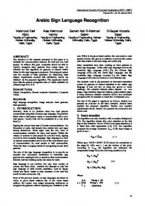
Figure-4. Mean square error versus epoch graph. The network was tested more than once during testing phase. The mean squared error tolerance was fixed at 0.0001 for training the samples. The learning rate and momentum factor were chosen as 0.25 and 0.9. RESULTS AND DISCUSSIONS Hand shape and tracking features constitute around 70% of characterization for any sign language. For hand tracking horn schunck optical flow algorithm is used and shape features are extracted in each frame with active contour level set model. The tracking features are set of velocity vectors extracted from each moving hand in the frames. Hand shapes from each frame are represented with hand outliners extracted with shape numbers. Two features from each frame are concatenated to represent signs in each frame. The entire process of the proposed continuous sign language recognizer is presented as a flow chart. From Figure-5, the video frames for this work represent a sign with a variable frame set. The set of frames can be identified using velocity vectors computed using HSOF algorithm. A start of sign (SOS) set frames is recognized
Figure-5. Frames from a sign video sequence showing Start of Sign (SOS) Frame in Green and End of Sign (EOS) Frame in Red. Frame numbers are published extreme left and right of the image. Few important frames are used for representation. A feature matrix is extracted between one SOS and EOS. This feature matrix becomes input to the classifier. Training to the Artificial Neural Network classifier is provided with this feature matrix. Error back propagation algorithm is used as a training algorithm. The error is calculated with gradient descent algorithm. The following FIS and ANN model is used for combined feature vector classification as shown in Figure-5. The details of weights, biases and learning rate values are randomly initialized and re iteratively updated with a least squares optimization of error.
8368
VOL. 11, NO. 13, JULY 2016
ARPN Journal of Engineering and Applied Sciences
ISSN 1819-6608
©2006-2016 Asian Research Publishing Network (ARPN). All rights reserved.
www.arpnjournals.com For testing the above process on the videos of continuous sign language, a camera setup is constructed. To ensure uniform lighting, two 23 luminance bulbs are erected at an angle of 45 degrees from the signer. A HD Sony camcorder at a distance of 22 meters ensures excellent HD videos of continuous sign language. For experimentation for this model a subset of Indian Sign Language is used. A total of 10 test subjects were used. Each performing the same set of sentences for Indian Sign Language. A continuous sentence comprising 50 words is chosen for our experimentation. The sentence used is “Hai, Good Morning, My Name is Kishore, I am Student of K.L.University, Studying final year Undergraduate Engineering, From Department of Electronics and Communications engineering, the college is located at a lush green surroundings, with estimated an area of around 50 acres, we are doing project on sign language, thank you”. Each video recording of the above sequence of sentences is averaged around 100 sec. This is because; the signers are not regular users of sign language. Sony camcorder outputs videos with a 30fps HD sequences with a frame size of. For a 100 sec sequence we are looking at 3000 frames for a sentence of 50 words. For 10 different signers the figure is 30000 frames. Different signers are selected to make the system signer independent of these 5 samples are used for training and 5 will be testing samples. From any 5 samples feature vector is built combining tracking position vectors from HSOF and shape outliner’s vectors from AC models, which will train artificial neural network.
Figure-6. Video frames showing results of HSOF tracking signers hand and head. The green arrows resembling velocity vectors along x and y directions. Here the signer is saying “HAI”. Horn Schunck optical flow is the tracker for hands in the video frames. The algorithm implements on two frames at a time and computes the velocity vectors in x and y directions. From these velocity vectors, we compute the position of the hand in the frame. Multiple
positions are extracted due to the some ambiguity in the hand positions. This is due to light intensity variations in the frames during capture. Hence the average position vector is obtained for each hand in the frames. The tracking using Horn schunck Optical Flow (HSOF) on Frames of Figure-5 is shown in Figure-6.
(a)
(b)
(c)
(d)
Figure-7. HSOF based sign segmentation. (a) Frame 52 (b) Frame 52 Segmentation output from HSOF (c) Frame 75 (d) Segmentation result of (c) with HSOF. The same HSOF algorithm can do the job of segmentation of moving objects in a video. The results of HSOF segmentation for a few frames are shown in Figure7. From Figure-7(b) and (d) the HSOF segmented hands fails to produce exact contours to represent shape features. Hence in this HSOF algorithm will only track hands. The final track on the continuous video sequence is given in Figure-8. Intermediate frames are displayed in Figure-4 out of a total frame count of 2998 frames.
Figure-8. Tracks of hands in a continuous sign video sequence used for experimentation. Right hand bounding box is in red color and for left hand green is used. ‘X’ and ‘Y’ are position vectors with respect to head of the signer. Head position is marked manually in the first frame. Figure-9 displays tracks in three dimensional spaces. A feature vector is generated by careful labeling to both hands of the signer. The vector varied from signer to signer as their hand speeds changed during sign acquisition. Hence the tracking feature space is
8369
VOL. 11, NO. 13, JULY 2016
ARPN Journal of Engineering and Applied Sciences
ISSN 1819-6608
©2006-2016 Asian Research Publishing Network (ARPN). All rights reserved.
www.arpnjournals.com normalized by generating intermediate lost values for fast signers and by removing repeated position vectors for slow signers. Finally for a particular signer with 50 words we have a 1996 50 2 matrix. Further normalization by temporal averaging, the tacking feature matrix is represented with 1996 50 , giving 1996 tacks for 50 words sequences. By using only tracking information it is impossible to determine the classification problem.
a) Right Hand Tracks
b) Left Hand Tracks
Figure-9. Hand tracks of (a) Right hand of signer (b) Left hand of signer. Hence shape information of hands should accompany the tracks to the input of the classifier. Hand shape extraction is accomplished with active contour model. The contour is placed in an area close to the head of the signer. This enables the AC segmentation algorithm to trigger only when there is significant movement near the torso of the signer. Figure-10 shows the AC segmentation process on a video frame of the signer. The contour is placed close to the torso of the signer to keep the number of iterations for segmentation to a minimum. The segmentation is near perfect and no further processing is required. The head and hand shape boundary numbers are considered as feature vector per frame. A set of frames are presented in Figure-11 for the sentence described above. Total numbers for frames in this particular video are around 2998. Only 699 frames have useful information that can be considered as feature vector design. These 699 frames are selected based on frame differencing model used in equation (20). Here threshold is set based on the velocity difference value. Large velocity value changes in frames are retained and those with lesser velocity gradient are discarded. The contours are extracted from the region boundaries of the segments. Hand and head segment contours are manually labeled as Head and hand contours. The extracted contours for a few frames are shown in Figure-12. The boundaries of the contours are given unique combination of numbers to uniquely identify a particular shape in the video frame. These labeled shape numbers are fused with tracking features for the same frame. A final feature matrix is an amalgamation of two important characteristics for machine understanding of sign language from video sequences.
Figure-10. Active contour segmentation on a Video frame. The feature vector for both training and testing is built based on velocity vector gradients. Lesser gradients marks Star of sign (SOS) and End of Sign (EOS) frames. All the middle frames will have a feature vector. In this work we have 50 words and hence we have 58 feature vectors. Each feature vector is represented by variable number of samples with both tracking and shape numbers. For a complete 50 word sentence we have 699 frame video. A complete tracking feature matrix is created from 6 position vectors obtained from tracking i.e. right hand position (x,y), left hand position and Fixed head position. Similarly hands and head are represented with 50 shape numbers per frame constitute shape feature matrix. Concatenating the two produces a 50 699 feature matrix that trains the fuzzy inference engine. The entire process of feature vector design is mapped diagrammatically.
Figure-11. Segmentation outputs of a few important frames form the video sequence. The frames are layered in horizontal format.
8370
VOL. 11, NO. 13, JULY 2016
ARPN Journal of Engineering and Applied Sciences
ISSN 1819-6608
©2006-2016 Asian Research Publishing Network (ARPN). All rights reserved.
www.arpnjournals.com
For individual words in the sentence, word matching score is computed with 5 samples for training and remaining 5 samples and the 5 already trained ones are used for testing the trained FIS and ANN. Table I gives values of WMS for the proposed method against the three other methods. The experimentation was done 5 times. The WMS values in the Table-1 are averaged values over 5 times. Each time training is accomplished with same training set for all models of sign language systems in Table-1. Figure-12. Extracted shape contours for few frames. The target matrix consists of 50 words in the sentence in the order of sequence described previously. To improve the efficiency of the training program, three more samples are added to the one derived feature matrix earlier. The training input vector is 200 699 whereas the target is 50 699 .Both the matrices are supplied as input to the Sugeno fuzzy inference engine and artificial neural network with 200 inputs and 50 targets. Least squares fit error is transmitted to update the weights after every iteration as described in section 5. Fuzzy rule set is generated with feature vectors. The model of Sugeno fuzzy inference used. In FIS training the intermediate weights are continuously updated with the least square error to minimize network performance. The least square error tolerance is fixed at 0.01 for training the samples. The learning rate and momentum factor were chosen as 0.241 and 0.25. Five layers in Sugeno FIS are fuzzy layer, product layer, normalized layer, de-fuzzy layer and output layer as discussed in section 5. The target matrix consists of 50 words in the sentence in the order of sequence described previously. To improve the efficiency of the training program, four more samples are added to the one derived feature matrix earlier. The training input vector is 200 699 whereas the target is 50 699 . Both the matrices are supplied as input to the neural network with 200 inputs and 50 targets. Gradient descent error is transmitted to update the weights after every iteration as described in section 6. Log sigmoid activation function is used in all the layers. The model of neural network object is created in MATLAB. In ANN back propagation training the networks weights and biases are continuously updated with the mean square error to minimize network performance. The mean square error tolerance is fixed at 0.01 for training the samples. The learning rate and momentum factor were chosen as 0.241 and 0.5. The training graph between mean square error and epochs for the neural network object is shown in figure 4. The performance of the proposed system is computed with word matching score given by
ms
Word Matching 100 Total Words
(24)
Table-1. Word Matching Scores for individual words in the sentence used in this work.
Hai
Word matching score-Proposed, SOF+AC+FIS 90
Word matching score-Proposed, HSOF+AC+ANN 90
good
80
90
morning
100
90
My
90
80
name
90
80
Is
100
90
Kishore
90
100
I
90
100
Words
Am
80
90
A
100
90
student
90
90
of
100
90
K
100
80
L
100
90
University
80
80
Studying
90
90
final
80
100
year
90
100
Undergraduate
80
90
Engineering
90
100
From
100
80
Department
80
90
of
100
90
Electronics
90
90
and
100
80
Communications
100
90
engineering
80
100
the
80
90
college
80
100
is
100
90
located
80
90
at
100
100
8371
VOL. 11, NO. 13, JULY 2016
ARPN Journal of Engineering and Applied Sciences
ISSN 1819-6608
©2006-2016 Asian Research Publishing Network (ARPN). All rights reserved.
www.arpnjournals.com a
100
100
lush
80
90
Green
80
90
surroundings
100
100
with
100
100
estimated
90
90
area
80
80
of
100
90
around
90
100
Fifty
100
100
acres,
90
80
we
90
90
Are
100
90
Doing
90
90
This
80
90
Sign
90
90
language
90
90
thank you
90
100
Total
90.8
91.2
CONCLUSIONS This work gives a multi feature model for identifying continuous gestures of Indian sign language with two most powerful classifiers, FIS and ANN. Videos of continuous signs are captured for 50 words forming meaningful sentences. Horn Schunck optical flow algorithm extracts tracking features of both hands providing position vectors of hands in each frame. Active Contour model on each frame extracts hand shapes features along with head portion. The combined feature matrix having tracking and shape features train the Sugeno fuzzy inference engine and Backpropagation ANN. The classified signs are mapped to text from the target matrix of FIS and ANN for converting those text inputs to voice commands with windows text-to-speech application programmable interface. Validating the proposed model by computing the word matching score for each word recognized by the FIS and ANN. The word matching score over multiple instances of training and testing of the FIS and ANN resulted in around 90.8% and 91.2% respectively. ANN produces better matching scores for extensive training compared to FIS. This work can be extended to include other characteristics of continuous sign language with Hidden Markov Models. REFERENCES [1] Zahid Halim, Ghulam Abbas. 2015. A Kinect-Based Sign Language Hand Gesture Recognition System for Hearing- and Speech-Impaired: A Pilot Study of Pakistani Sign Language. Assistive Technology. 27(1): 34-43.
[2] Gaolin Fang and Wen Gao. 2007. Large Vocabulary Contineous Sign Language Recognition Based on Trnsition-Movement Models. IEEE Transaction on Systems, MAN, and Cybernetics. 37(1): 1-9. [3] T. Starner and A. Pentland. 1992. Real-Time American Sign Language Recognition from video using Hidden Markov Models. Technical Report, MIT Media laboratory Perceptual computing section, Technical Report no. 375. [4] Ming-Hsuan Yang and Narendra Ahuja. 2002. Extraction of 2D Motion Trajectories and its Application to Hand Gesture Recognition. IEEE Transaction on Pattern Analysis and Machine Intelligence. 24(8): 1061-1074. [5] W. Stokoe, D. Casterline, and C. Croneberg. 1965. A Dictionary of American Sign Language on Linguistic Principles. Gallaudet College Press, Washington D.C., USA. [6] M.K.Bhuyan and P.K.Bora. A Frame Work of Hand Gesture Recognition with Applications to Sign Language. IEEE Annual India Conference. pp. 1-6. [7] Rini Akmeliawati, Melanie Po-Leen Ooi and Ye Chow Kuang. 2006. Real-Time Malaysian Sign Language Translation Using Color Segmentation and Neural Network. IEEE on Instrumentation and Measurement Technology Conference Proceeding, Warsaw, Poland. pp. 1-6. [8] Nariman Habili, Cheng Chew Lim and Alireza Moini. 2004. Segmentation of The Face and Hands in Sign Language Video Sequences Using Color and Motion Cues. IEEE Transactions on Circuits and Systems for Video Technology. 14(8): 1086-1097. [9] Yu Zhou and Xilin Chen. 2010. Adaptive sign language recognition with Exemplar extraction and MAP/IVFS. IEEE signal processing letters. 17(3): 297-300. [10] Och J., Ney. H. 2002. Discriminative training and maximum entropy models for statistical machine translation. In: Annual Meeting of the Ass. For Computational Linguistics (ACL), Philadelphia, PA. pp. 295-302. [11] Sumita E., Akiba Y., Doi T. 2003. A Corpus-Centered Approachto Spoken Language Translation. Conf. of the Europ. Chapter of the Ass. For Computational Linguistics (EACL), Budapest, Hungary. pp. 171-174. [12] Casacuberta F., Vidal E. 2004. Machine translation with inferred stochastic finite-state transducers. Computational Linguistics. 30(2): 205-225.
8372
VOL. 11, NO. 13, JULY 2016
ARPN Journal of Engineering and Applied Sciences
ISSN 1819-6608
©2006-2016 Asian Research Publishing Network (ARPN). All rights reserved.
www.arpnjournals.com [13] Kishore P.V.V, Rajesh Kumar P. 2012. Segment, Track, Extract, Recognize and Convert Sign Language Videos to Voice/Text. International Journal of Advanced Computer Science and Applications (IJACSA) ISSN (Print)-2156, 3(6): 35-47.
[23] Israel-Jost Vincent, et al. 2014. On the implementation of the multi-phase region segmentation, solving the hidden phase problem. Image Processing (ICIP), 2014 IEEE International Conference on. IEEE.
[14] Kishore P.V.V., Sastry A.S.C.S., Kartheek A. 2014. Visual-verbal machine interpreter for sign language recognition under versatile video backgrounds. 2014 First International Conference on Networks & Soft Computing (ICNSC). pp. 135-140.
[24] Cai Bo, et al. 2016. A Stable Image Segmentation Framework Using Gray and Contrast Guided Active Contour.
[15] Kishore P. V. V., S. R. C. Kishore and M. V. D. Prasad. 2013. Conglomeration of Hand Shapes and Texture Information for Recognizing Gestures of Indian Sign Language Using Feed Forward Neural Networks. International Journal of engineering and Technology (IJET), ISSN: 0975-4024, 5(5): 37423756. [16] Kishore P.V.V., Prasad M.V.D., Prasad C.R., Rahul R. 2015. 4-Camera model for sign language recognition using elliptical fourier descriptors and ANN. 2015 International Conference in Signal Processing and Communication Engineering Systems (SPACES). pp. 34-38. [17] Yikai Fang, Kongqiao Wang, Jian Cheng and Hanqing Lu. 2007. A Real-Time Hand Gesture Recognition Method. In: Proceedings of IEEE International Conference on Multimedia and Expo (ICME 2007), Beijing, China. pp. 995-998. [18] Kishore, P. V. V., et al. 2015. Crowd Density Analysis and tracking. Advances in Computing, Communications and Informatics (ICACCI), 2015 International Conference on. IEEE. [19] C.B. Traxler. 2000. The Stanford Achievement Test, 9th Edition: National Norming and Performance Standards for Deaf and Hard-of-Hearing Students. Journal of Deaf Studies and Deaf Education. 5(4): 337-348. [20] Li, Qiang, Tingquan Deng, and Wei Xie. 2016. Active contours driven by divergence of gradient vector flow. Signal Processing. 120: 185-199.
[25] Luo, Junfeng, and Jinwen Ma. 2015. Image segmentation with the competitive learning based MS model. Image Processing (ICIP), 2015 IEEE International Conference on. IEEE. [26] M. Kass, A Witkin, D Terzopoulos. 1987. Snakes: active Contour Models. Int. J. of Computer Vision. pp. 321-331. [27] Osher S., Sethian J. 1988. Fronts propagating with curvature-dependant speed: algorithms based on Hammilton-Jacobi formulations. J. Comput. Phys. 79(1): 12-49. [28] Anitha P. and S. Vijayakumar. 2015. Fuzzy-Based Sign Language Interpreter. Artificial Intelligence and Evolutionary Algorithms in Engineering Systems. Springer India. pp. 555-563. [29] Brox Piedad, et al. 2014. Edge-adaptive spatial video de-interlacing algorithms based on fuzzy logic. Consumer Electronics, IEEE Transactions on 60.3: 375-383. [30] L. X. Wang and I. M. Mendel. 1992. Generating fuzzy rules by learning from examples. IEEE Trans. Syst., Man, Cyben. 22(6): 1414-1427. [31] Levenberg K. 1944. A method for the solution of certain nonlinear problems in least-squares. Quart. Appl. Math. II, pp. 164-168. [32] Rini Akmeliawati, Melanie Po-Leen Ooi and Ye Chow Kuang. 2006. Real-Time Malaysian Sign Language Translation Using Color Segmentation and Neural Network. IEEE on Instrumentation and Measurement Technology Conference Proceeding, Warsaw, Poland. pp. 1-6.
[21] Liu, Zhigui, Junbo Wang, and Yuyu Zhu. 2015. A Study of Active Contour Segmentation Models based on Automatic Initial Contour. International Journal of Signal Processing, Image Processing and Pattern Recognition. 8(4): 201-214. [22] D. Terzopoulos and K. Fleischer. 1988. Deformable models. The Visual Computer. 4(6): 306-331.
8373