Aug 26, 2011 - virtual machine via a SSH client and can upload files via an SFTP or SCP ..... editing, such as Adobe Photoshop, Adobe Illustrator, Adobe Fire-.
Universidade Estadual de Campinas Faculdade de Engenharia Elétrica e de Computação Departamento de Comunicações
Contributions to the design and development process of interactive applications for digital TV based on Ginga-NCL (Contribuições para o desenvolvimento de aplicações interativas para TV digital baseadas em Ginga-NCL)
Autor: Julio Humberto León Ruiz Orientador: Prof. Dr. Yuzo Iano
Master’s Degree Dissertation presented to the School of Electrical and Computer Engineering as a requirement to obtain the degree of Master of Science in Electrical Engineering. Area of Concentration: Telematics and Telecommunications
Jury Members
Prof. Dr. Yuzo Iano (Chair) — DECOM/FEEC/UNICAMP Prof. Dr. Guillermo Kemper Vásquez — USMP – Lima, Peru Prof. Dr. Luis César Martini — DECOM/FEEC/UNICAMP
Campinas – SP August 2011
FICHA CATALOGRÁFICA ELABORADA PELA BIBLIOTECA DA ÁREA DE ENGENHARIA E ARQUITETURA - BAE - UNICAMP
León Ruiz, Julio Humberto L553c
Contribuições para o desenvolvimento de aplicações interativas para TV digital baseadas em Ginga-NCL / Julio Humberto León Ruiz. – Campinas, SP: [s.n.], 2011.
Orientador: Yuzo Iano Dissertação de Mestrado - Universidade Estadual de Campinas. Faculdade de Engenharia Elétrica e de Computação.
1. Televisão digital. I. Iano, Yuzo. II. Universidade Estadual de Campinas. Faculdade de Engenharia Elétrica e de Computação. III. Título
Título em Inglês:
Contributions to the design and development process of interactive applications for digital TV based on Ginga-NCL
Palavras-chave em Inglês:
Digital television
Área de concentração:
Telecomunicações e Telemática
Titulação:
Mestre em Engenharia Elétrica
Banca Examinadora:
Guillermo Leopoldo Kemper Vásquez, Luiz César Martini
Data da defesa:
26-08-2011
Programa de Pós-Graduação:
Engenharia Elétrica
ii
iii
iv
Abstract Interactivity for digital television is, nowadays, a very important feature to stablish a communication pathway between users and broadcasters, due to digital television’s current status in Brazil. The Ginga middleware, still in development status, presents an opportunity for achieving interactivity via Ginga-NCL, a framework that allows application development and deployment using NCL and Lua programming languages. However, there are not standardised ways to develop applications, the currently available receivers in the market are very limited in hardware, and released applications will not be able to always execute flawlessly without standards or guidelines to optimise them. The author’s work offers a new perspective on graphical environment development for interactive applications with techniques to optimise against the limiting factors, and presents an open-source library for implementing a virtual keyboard in any Ginga-NCL application as well. Keywords: Digital Television, ISDB-Tb, Interactivity, Ginga, NCL, NCLua, GUI Design, Virtual Keyboard.
v
vi
Resumo No entorno atual da televisão digital no Brasil, a interatividade é uma característica importante para se estabelecer uma plataforma de comunicação entre os usuários e as emissoras. O middleware Ginga, ainda em desenvolvimento, se apresenta como uma oportunidade para a interatividade por meio do Ginga-NCL, um framework que permite o desenvolvimento de aplicações usando as linguagens NCL e Lua. Porém, as formas de se implementar aplicações não são padronizadas, uma vez que os receptores no mercado são limitados em hardware e as aplicações nem sempre poderão ser executadas sem seguir algumas regras ou restrições para se otimizar as aplicações. Este trabalho oferece uma nova perspectiva sobre o desenvolvimento de gráfico de aplicações interativas, com técnicas para se otimizar os parâmetros limitantes, além de uma biblioteca de código aberto para se implementar um teclado virtual em qualquer aplicação Ginga-NCL. Palavras-chave: Televisão Digital, ISDB-Tb, Interatividade, NCL.
vii
viii
Acknowledgements I would like to thank my family, who gave me all their time, love, and support, which were essential to me to accomplish this and all my achievements. I am grateful to Prof. Yuzo Iano whose patience, guidance and wisdom enabled me to carry out this work. I am indebted to my colleagues Cibele and Ricardo, whose moral support and work together aided me in obtaining results. I would like to show my gratitude to my laboratory partners for their suggestions and criticism. It is a pleasure to thank FAEPEX/CAPES for the financial support which made this thesis possible.
ix
x
Acknowledgements I must express my gratitude to the CAPES RH-TVD (Coordenação de Aperfeiçoamento de Pessoal de Nível Superior) programme for the financial support and the academic incentive that enabled the realisation of this thesis. Agradeço ao programa CAPES RH-TVD da Coordenação de Aperfeiçoamento de Pessoal de Nível Superior tanto pelo apoio financeiro quanto pelo incentivo acadêmico para que este trabalho pudesse ser realizado.
xi
xii
To God and my family
xiii
xiv
Published Papers 1. C. A. Makluf et al. Estudo de tecnologias 3G visando à estruturação do canal de retorno da TV digital. In Proceedings of LatinDisplay 2010/IDRC 2010, São Paulo-SP, Brazil, 2010.
xv
xvi
Table of Contents List of Figures
xxi
List of Tables
xxiii
List of Codes
xxv
Glossary
xxvii
CHAPTER 1
Introduction
1
1.1
Background . . . . . . . . . . . . . . . . . . . . . . . . . . . . . . . . . . . . . . . . . . .
1
1.2
Motivation and Objectives . . . . . . . . . . . . . . . . . . . . . . . . . . . . . . . . . . .
3
1.3
Chapter Organisation . . . . . . . . . . . . . . . . . . . . . . . . . . . . . . . . . . . . . .
4
CHAPTER 2
Theoretical Review
9
2.1
Middleware . . . . . . . . . . . . . . . . . . . . . . . . . . . . . . . . . . . . . . . . . . .
9
2.2
Digital Television System . . . . . . . . . . . . . . . . . . . . . . . . . . . . . . . . . . .
11
2.3
Current Middleware Implementations . . . . . . . . . . . . . . . . . . . . . . . . . . . .
13
2.3.1
DVB and MHP . . . . . . . . . . . . . . . . . . . . . . . . . . . . . . . . . . . . .
13
2.3.2
GEM . . . . . . . . . . . . . . . . . . . . . . . . . . . . . . . . . . . . . . . . . . .
15
2.3.3
ATSC and DASE . . . . . . . . . . . . . . . . . . . . . . . . . . . . . . . . . . . .
16
2.3.4
ISDB-T and ARIB . . . . . . . . . . . . . . . . . . . . . . . . . . . . . . . . . . . .
16
ISDB-Tb and the Ginga Middleware . . . . . . . . . . . . . . . . . . . . . . . . . . . . .
17
2.4.1
ISDB-Tb . . . . . . . . . . . . . . . . . . . . . . . . . . . . . . . . . . . . . . . . .
17
2.4.2
Ginga . . . . . . . . . . . . . . . . . . . . . . . . . . . . . . . . . . . . . . . . . . .
18
Interactivity . . . . . . . . . . . . . . . . . . . . . . . . . . . . . . . . . . . . . . . . . . .
21
2.4
2.5
xvii
xviii
TABLE OF CONTENTS Interactive Services . . . . . . . . . . . . . . . . . . . . . . . . . . . . . . . . . . .
23
MPEG-2 Transport Stream . . . . . . . . . . . . . . . . . . . . . . . . . . . . . . . . . . .
24
2.6.1
DSM-CC Protocol and Data Carousel . . . . . . . . . . . . . . . . . . . . . . . .
25
2.6.2
Metadata Tables . . . . . . . . . . . . . . . . . . . . . . . . . . . . . . . . . . . . .
26
2.5.1 2.6
CHAPTER 3
Programming Languages and Development Tools for Ginga
27
Nested Context Model . . . . . . . . . . . . . . . . . . . . . . . . . . . . . . . . . . . . .
27
3.1.1
NCM Elements . . . . . . . . . . . . . . . . . . . . . . . . . . . . . . . . . . . . .
27
3.1.2
NCM Events . . . . . . . . . . . . . . . . . . . . . . . . . . . . . . . . . . . . . . .
31
3.2
Nested Context Language . . . . . . . . . . . . . . . . . . . . . . . . . . . . . . . . . . .
32
3.3
NCLua API . . . . . . . . . . . . . . . . . . . . . . . . . . . . . . . . . . . . . . . . . . .
34
3.4
Development Tools . . . . . . . . . . . . . . . . . . . . . . . . . . . . . . . . . . . . . . .
35
3.4.1
Composer . . . . . . . . . . . . . . . . . . . . . . . . . . . . . . . . . . . . . . . .
35
3.4.2
Eclipse . . . . . . . . . . . . . . . . . . . . . . . . . . . . . . . . . . . . . . . . . .
36
3.4.3
NCL Eclipse . . . . . . . . . . . . . . . . . . . . . . . . . . . . . . . . . . . . . . .
36
3.4.4
Lua Eclipse . . . . . . . . . . . . . . . . . . . . . . . . . . . . . . . . . . . . . . .
38
3.4.5
Ginga-NCL Virtual Set-top Box . . . . . . . . . . . . . . . . . . . . . . . . . . . .
39
Related Projects . . . . . . . . . . . . . . . . . . . . . . . . . . . . . . . . . . . . . . . . .
41
3.5.1
LuaTV . . . . . . . . . . . . . . . . . . . . . . . . . . . . . . . . . . . . . . . . . .
41
3.5.2
LuaComp . . . . . . . . . . . . . . . . . . . . . . . . . . . . . . . . . . . . . . . .
42
3.5.3
MoonDo . . . . . . . . . . . . . . . . . . . . . . . . . . . . . . . . . . . . . . . . .
44
3.1
3.5
CHAPTER 4 4.1
4.2
GUI Design Techniques and Guidelines
47
Principles of UI Design . . . . . . . . . . . . . . . . . . . . . . . . . . . . . . . . . . . . .
48
4.1.1
Target Audience . . . . . . . . . . . . . . . . . . . . . . . . . . . . . . . . . . . . .
49
4.1.2
Constraints and Criteria . . . . . . . . . . . . . . . . . . . . . . . . . . . . . . . .
51
Design Techniques and Guidelines . . . . . . . . . . . . . . . . . . . . . . . . . . . . . .
52
4.2.1
The Golden Rules . . . . . . . . . . . . . . . . . . . . . . . . . . . . . . . . . . . .
53
4.2.2
Grid-based design . . . . . . . . . . . . . . . . . . . . . . . . . . . . . . . . . . .
54
4.2.3
Gestalt Laws . . . . . . . . . . . . . . . . . . . . . . . . . . . . . . . . . . . . . . .
57
TABLE OF CONTENTS
4.3
xix
4.2.4
Colours and Transparency . . . . . . . . . . . . . . . . . . . . . . . . . . . . . . .
61
4.2.5
Viewing Patterns . . . . . . . . . . . . . . . . . . . . . . . . . . . . . . . . . . . .
62
4.2.6
Safe Areas . . . . . . . . . . . . . . . . . . . . . . . . . . . . . . . . . . . . . . . .
63
Layout Creation Guidelines . . . . . . . . . . . . . . . . . . . . . . . . . . . . . . . . . .
64
4.3.1
Sketching the Concept . . . . . . . . . . . . . . . . . . . . . . . . . . . . . . . . .
64
4.3.2
Drawing the Interface . . . . . . . . . . . . . . . . . . . . . . . . . . . . . . . . .
64
4.3.3
Marking Coordinates and Dimensions . . . . . . . . . . . . . . . . . . . . . . .
65
4.3.4
Implementation . . . . . . . . . . . . . . . . . . . . . . . . . . . . . . . . . . . . .
66
CHAPTER 5
NCLua Contributions
69
5.1
Object-Oriented Programming in Lua . . . . . . . . . . . . . . . . . . . . . . . . . . . .
70
5.2
NCLua Virtual Keyboard . . . . . . . . . . . . . . . . . . . . . . . . . . . . . . . . . . .
72
5.2.1
Conception . . . . . . . . . . . . . . . . . . . . . . . . . . . . . . . . . . . . . . .
72
5.2.2
Class Description . . . . . . . . . . . . . . . . . . . . . . . . . . . . . . . . . . . .
74
CHAPTER 6
Conclusions
Bibliography
83 87
APPENDIX A
NCLua Virtual Keyboard
91
APPENDIX B
Sample Application
99
xx
TABLE OF CONTENTS
List of Figures Figure 2.1
Multiplexing for Digital Television . . . . . . . . . . . . . . . . . . . . . . . . . .
10
Figure 2.2
An interface problem with a simple solution . . . . . . . . . . . . . . . . . . . .
10
Figure 2.3
Basic structure of the elements of a middleware . . . . . . . . . . . . . . . . . .
11
Figure 2.4
A generic digital television architecture . . . . . . . . . . . . . . . . . . . . . . .
12
Figure 2.5
A digital television system . . . . . . . . . . . . . . . . . . . . . . . . . . . . . .
14
Figure 2.6
Relationship between GEM and GEM-based specifications . . . . . . . . . . . .
16
Figure 2.7
Different allocation cases for the 6 MHz band . . . . . . . . . . . . . . . . . . .
18
Figure 2.8
Ginga Middleware Architecture . . . . . . . . . . . . . . . . . . . . . . . . . . . .
19
Figure 2.9
Application Environment Structure . . . . . . . . . . . . . . . . . . . . . . . . .
19
Figure 2.10 Interactivity Context for Ginga-based Devices . . . . . . . . . . . . . . . . . . .
21
Figure 2.11 Model of interactive digital television system . . . . . . . . . . . . . . . . . . .
22
Figure 2.12 Example of an EPG . . . . . . . . . . . . . . . . . . . . . . . . . . . . . . . . . . .
23
Figure 2.13 Simplified Model of the MPEG-2 Transport and Program Stream Multiplexing
24
Figure 2.14 TS Packet Structure . . . . . . . . . . . . . . . . . . . . . . . . . . . . . . . . . . .
25
Figure 3.1
Overview of NCM class hierarchy . . . . . . . . . . . . . . . . . . . . . . . . . .
28
Figure 3.2
Interfaces of an NCM Node . . . . . . . . . . . . . . . . . . . . . . . . . . . . . .
30
Figure 3.3
NCM event state machine . . . . . . . . . . . . . . . . . . . . . . . . . . . . . . .
31
Figure 3.4
Multiple Views of the Composer Authoring Tool . . . . . . . . . . . . . . . . .
35
Figure 3.5
Error Validation and Possible Corrections . . . . . . . . . . . . . . . . . . . . . .
37
Figure 3.6
Program visualisation of the element . . . . . . . . . . . . . . . . . .
37
Figure 3.7
Evaluating Lua scripts using the pre-configured interpreter . . . . . . . . . . .
38
Figure 3.8
Ginga-NCL Virtual STB Interface . . . . . . . . . . . . . . . . . . . . . . . . . . .
40
xxi
xxii Figure 3.9
LIST OF FIGURES LuaTV API context within Ginga architecture . . . . . . . . . . . . . . . . . . . .
41
Figure 3.10 LuaTV API Widgets Package . . . . . . . . . . . . . . . . . . . . . . . . . . . . .
42
Figure 3.11 Different Views of the LuaComp tool . . . . . . . . . . . . . . . . . . . . . . . .
44
Figure 3.12 MoonDo Graphic Components . . . . . . . . . . . . . . . . . . . . . . . . . . . .
45
Figure 4.1
Remote Control for User Perception Tests . . . . . . . . . . . . . . . . . . . . . .
49
Figure 4.2
Example of a Common Remote Control . . . . . . . . . . . . . . . . . . . . . . .
51
Figure 4.3
Different Television Aspect Ratios . . . . . . . . . . . . . . . . . . . . . . . . . .
53
Figure 4.4
An Example of Grid-based Design . . . . . . . . . . . . . . . . . . . . . . . . . .
56
Figure 4.5
Gestalt Law of Balance/Symmetry . . . . . . . . . . . . . . . . . . . . . . . . . .
57
Figure 4.6
Gestalt Law of Continuity . . . . . . . . . . . . . . . . . . . . . . . . . . . . . . .
58
Figure 4.7
Gestalt Law of Closure . . . . . . . . . . . . . . . . . . . . . . . . . . . . . . . . .
58
Figure 4.8
Gestalt Law of Figure-Ground . . . . . . . . . . . . . . . . . . . . . . . . . . . .
58
Figure 4.9
Gestalt Law of Focal Point . . . . . . . . . . . . . . . . . . . . . . . . . . . . . . .
59
Figure 4.10 Gestalt Law of Isomorphic Correspondence: A Help Icon . . . . . . . . . . . .
59
Figure 4.11 Gestalt Law of Prägnanz (Good Form) . . . . . . . . . . . . . . . . . . . . . . . .
60
Figure 4.12 Gestalt Law of Proximity: Three Horizontal Rows . . . . . . . . . . . . . . . . .
60
Figure 4.13 Gestalt Law of Similarity: Triangle inside a Square . . . . . . . . . . . . . . . .
60
Figure 4.14 Gestalt Law of Simplicity . . . . . . . . . . . . . . . . . . . . . . . . . . . . . . .
61
Figure 4.15 Gestalt Law of Unity/Harmony . . . . . . . . . . . . . . . . . . . . . . . . . . .
61
Figure 4.16 Typical Page Scanning “Z” Pattern . . . . . . . . . . . . . . . . . . . . . . . . . .
62
Figure 4.17 BBCi Viewing Pattern . . . . . . . . . . . . . . . . . . . . . . . . . . . . . . . . .
63
Figure 4.18 Action-Safe and Graphic-Safe Areas for a Wide-Screen (16:9) format TV Screen
64
Figure 4.19 Layout Sketch for a Form Application . . . . . . . . . . . . . . . . . . . . . . . .
65
Figure 4.20 Drawn Concept . . . . . . . . . . . . . . . . . . . . . . . . . . . . . . . . . . . . .
66
Figure 4.21 Marking Coordinates and Dimensions . . . . . . . . . . . . . . . . . . . . . . .
66
Figure 4.22 Flat vs. Blended Colours . . . . . . . . . . . . . . . . . . . . . . . . . . . . . . . .
68
Figure 5.1
Virtual Keyboard, version 1 . . . . . . . . . . . . . . . . . . . . . . . . . . . . . .
73
Figure 5.2
Virtual Keyboard Sample Application . . . . . . . . . . . . . . . . . . . . . . . .
81
List of Tables Table 2.1
DVB standards . . . . . . . . . . . . . . . . . . . . . . . . . . . . . . . . . . . . . .
14
Table 4.1
Mandatory Remote Control Keys . . . . . . . . . . . . . . . . . . . . . . . . . . .
50
Table 4.2
Maximum bitrate values for each type of service . . . . . . . . . . . . . . . . . .
67
Table 5.1
Attributes of the KbElement class . . . . . . . . . . . . . . . . . . . . . . . . . . .
74
Table 5.2
Methods of the KbElement class . . . . . . . . . . . . . . . . . . . . . . . . . . . .
75
Table 5.3
Attributes of the KeyBoard class . . . . . . . . . . . . . . . . . . . . . . . . . . . .
75
Table 5.4
Methods of the KeyBoard class . . . . . . . . . . . . . . . . . . . . . . . . . . . . .
77
xxiii
xxiv
LIST OF TABLES
List of Codes Code 3.1
Sample NCL Code . . . . . . . . . . . . . . . . . . . . . . . . . . . . . . . . . . . .
32
Code 5.1
Metatable-based Object Orientation . . . . . . . . . . . . . . . . . . . . . . . . . .
70
Code 5.2
Defining Methods . . . . . . . . . . . . . . . . . . . . . . . . . . . . . . . . . . . .
70
Code 5.3
Direct Access to Object Variables . . . . . . . . . . . . . . . . . . . . . . . . . . .
71
Code 5.4
Alternative Method for Object Orientation . . . . . . . . . . . . . . . . . . . . . .
71
Code 5.5
Creating a layout content array . . . . . . . . . . . . . . . . . . . . . . . . . . . . .
80
Code 5.6
Multiple Keyboard Layouts . . . . . . . . . . . . . . . . . . . . . . . . . . . . . .
80
xxv
xxvi
LIST OF CODES
Glossary 8-VSB
Eight Level Vestigial Sideband
AAC
Advanced Audio Coding
AC
Audio Coding
API
Application Programming Interface
ARIB
Association of Radio Industries and Business
ATSC
Advanced Television Systems Committee
BST-OFDM
Band-Segmented Transmission - Orthogonal Frequency Division Multiplexing
CAT
Conditional Access Table
Codec
Encoder/Decoder
COFDM
Coded Orthogonal Frequency Division Multiplexing
DASE
Digital Television Application Software Environment
DSM-CC
Digital Storage Media – Command and Control
DVB
Digital Video Broadcasting
EDTV
Enhanced Definition Television
EPG
Electronic Program Guide
GEM
Globally Executable MHP xxvii
xxviii
Glossary
GUI
Graphic User Interface
HD
High Definition
HDTV
High Definition Television
HTML
HyperText Markup Language
HTTP
HyperText Transfer Protocol
IDE
Integrated Development Environment
IPTV
Internet Protocol Television
ISDB
Integrated Services Digital Broadcasting
ISDB-T
Integrated Services Digital Broadcasting - Terrestrial
ISDB-Tb
Integrated Services Digital Broadcasting - Terrestrial, version B
JPEG
Joint Photographic Experts Group
JVM
Java Virtual Machine
LCD
Liquid Crystal Display
LED
Light-Emitting Diode
MHEG
Multimedia and Hypermedia Experts Group
MHP
Multimedia Home Platform
Modem
Modulator/Demodulator
MPEG
Moving Picture Experts Group
NCL
Nested Context Language
NCM
Nested Context Model
NIT
Network Information Table
Glossary
xxix
NTSC
National Television System Committee
OOP
Object-Oriented Programming
OTT TV
Over-the-top Television
PAL
Phase Alternating Line
PAT
Program Assosiation Table
PES
Packetised Elementary Stream
PID
Packet Identifier
PMT
Program Map Table
PNG
Portable Network Graphics
PS
Program Stream
PSI
Program Specific Information
PUC-RIO
Pontifícia Universidade Católica do Rio de Janeiro
RTOS
Real-Time Operating System
RTP
Real-time Transport Protocol
SBTVD
Sistema Brasileiro de Televisão Digital
SDTV
Standard Definition Television
SECAM
Séquentiel Couleur à Mémoire
SNR
Signal-to-noise ratio
STB
Set-Top Box
TDT
Time and Date Table
TS
Transport Stream
xxx
Glossary
UFMA
Universidade Federal do Maranhão
UNB
Universidade de Brasília
WYSIWYG
What-You-See-Is-What-You-Get
XML
Extensible Markup Language
Chapter 1
Introduction
D
uring the last few years, digital television has started to get plenty of attention in the media. Marketing campaigns were launched to get the masses to purchase new TV sets and receivers, or set-top boxes (STBs), that support digital television in order to watch
the World Cup, or some new High Definition (HD) soap opera. Before going any further, a brief look into the history of digital television and the development
of digital television in Brazil should be taken to have a better understanding of the work described in this thesis and to analyse the quality of its contributions.
1.1 Background In the course of the last century, analogue television was born and had huge commercial success worldwide. Several companies conducted research and established standards for broadcasting, displaying and content creating processes. The standards for analogue TV were developed in three different parts of the world. In the United States of America, the National Television System Committee (NTSC) developed the analogue television system that was used in most of North and South America, and some Asian countries. In Europe, in 1963, the Phase Alternating Line (PAL) system was developed and adopted by most Western European countries as their analogue television colour encoding system. However, France developed, in 1967, the Séquentiel Couleur à Mémoire (SECAM) which is French for “Sequential Colour with Memory” and did not switch to PAL as the rest of 1
Chapter 1 - Introduction
2
Western Europe. Finally, in 1972, a fourth variant was developed in Brazil: PAL-M. During the 90’s, the American, European, and Japanese major research centres worked together to develop the foundations of digital television. Each of them developed their own standards for digital television, as they did before for analogue television. These standards are known as Advanced Television Systems Committee (ATSC), Digital Video Broadcasting (DVB) and Integrated Services Digital Broadcasting (ISDB) for the American, European and Japanese respectively [1]. Besides the American, European, and Japanese, the Brazilian research centres also began studies about digital television formats. This research was based in ATSC, DVB and ISDB, as those were the most current standards at the time [2]. From those studies, the Brazilian government decided to adopt ISDB-T (Integrated Services Digital Broadcasting - Terrestrial) as the Brazilian digital television standard base. It was from that base that Brazil decided to implement several improvements to satisfy the need for mobility, portability, low cost for consumers, interactivity and high definition video [1]. These improvements led to the development of the new Brazilian-Japanese standard, ISDB-Tb (Integrated Services Digital Broadcasting - Terrestrial, version B) also called Sistema Brasileiro de Televisão Digital (SBTVD). The new ISDB-Tb was made from research carried out in Brazilian research centres, with new features such as a new middleware Ginga, which is the platform for interactivity and the use of a new compression standard, h.264 (ISO/IEC 14496-10 - MPEG-4 Part 10, Advanced Video Coding) replacing MPEG-2 used in the Japanese version, achieving greater compression rates. Digital television was the way to address certain problems present in analogue transmission back then, such as random white noise, ghosting, and degenerative video quality. The loss in video quality depends on the ratio between the signal and noise power, called signal-to-noise ratio (SNR) [3]. Besides that, digital television provides the audience with very large image resolutions, resulting in great image quality. This is known as High Definition Television (HDTV). However, HDTV is not the only great benefit digital television has to offer; a digital television system offers much more than just images and audio, beyond any analogue television scope. This special feature is what allows a new level of possibilities by using digital television as a platform to provide one more communication channel between the user and the broadcasters or content providers: interactivity.
Chapter 1 - Introduction
3
A non-linear programme is a TV show composed by video, audio and additional data that is also transmitted along. This data contains other audio (different languages, director’s comments, etc.) as well as images and text enclosed in an application that is linked to the programme in time and space. This relationships between elements can be set to execute independently, or to wait for the viewer’s command (thus, being an interactive application) [4]. The platform for interactivity in ISDB-Tb is called Ginga. It is the middleware, developed in Brazil as an improvement over Japanese ISDB’s middleware, Association of Radio Industries and Business (ARIB), and allows interactivity as well as other features that will be explained in detail in Chapter 2 [5]. Besides ISDB-Tb, DVB also has a middleware that provides the user with interactivity.
1.2 Motivation and Objectives The recent increase in demand for interactive services in various multimedia platforms (specially with the inclusion of Internet connectivity to many devices, smartphones, etc.) and the rise of the social networks started to create a certain urge for interactivity for everything by the users. Television is no exception; therefore, design and development for these applications is becoming, each time, more appealing for broadcasters and content providers. During the initial research for this dissertation, several tests applications were developed as a way to get familiarised with the Ginga middleware, in particular, the Ginga-NCL interactive platform, and to obtain a deeper understanding of the tools and processes. The results were very inefficient, some of them did not even load properly in the STBs. Since the technology and the standard are new and still in development, the need for certain guidelines or methods to design and develop properly an application was imperative. This was the motivating factor for this dissertation. When researching the possibilities for implementing interactive applications, and, in particular, how to develop open-source tools for everyone to use, there was a certain topic that rose a particular issue: there is no native object orientation in the Lua language (as will be explained in Section 5.1). The experiments carried out had issues with object orientation for scalable parametric objects that would later become the NCLua Virtual Keyboard presented in Section 5.2. Learning how to resolve this and sharing it with other developers as a form of open-source library was a very important
Chapter 1 - Introduction
4 motivating factor as well.
The objectives of this work are focused on providing with a brief background about digital television, the Ginga middleware and the return path for interactivity; introducing the current development tools and environments available at the current time of writing; proposing a set of Graphic User Interface (GUI) design techniques to take the most advantage of the resources available and to present the user with neat, tidy and useful interactive interfaces; and to present the open-source NCLua Virtual Keyboard library, to aid in interactive application design and development, and to motivate code sharing and open-source projects among researchers.
1.3 Chapter Organisation This dissertation is organised as follows: • Chapter 1 introduces the reader with a brief background about current digital TV standards as well as the motivation for this work. • In Chapter 2, presents a theoretical review about Ginga and the technologies involved around the middleware. • Chapter 3 brings an overview on the current development environments, as well as other projects regarding frameworks and tools for Ginga-NCL. • In Chapter 4, the proposed GUI design techniques are described, from basic GUI elements to full example layouts. Common problems are described and workarounds are proposed. • Chapter 5 presents an open-source virtual keyboard completely written in NCLua, describing its classes and methods, and an example of usage in a real application. • Finally, Chapter 6 presents the conclusions and proposes future projects.
Introdução
D
urante os últimos anos, a televisão digital começou a despertar a atenção da mídia. Campanhas de marketing foram lançadas para que a população compre os novos receptores de TV, conhecidos como set-top box (STB), que suportam a televisão digital,
para assistir, por exemplo, a copa do mundo, ou uma novela em Alta Definição (HD). Para se ter uma melhor compreensão do trabalho descrito e analisar as suas contribuições, primeiramente, será feito um breve histórico da televisão digital e, em particular, do desenvolvimento da televisão digital no Brasil.
Histórico No decorrer do século passado, a televisão analógica nasceu e teve um grande sucesso comercial ao redor do mundo. Várias empresas realizaram pesquisas a fim de estabelecer padrões para a radiodifusão, exibição e criação de conteúdo. Os padrões de TV analógica foram desenvolvidos em três partes diferentes do mundo. Nos Estados Unidos, o National Television System Committee (NTSC) desenvolveu um sistema que foi utilizado na maioria do norte e sul da América, e também alguns países da Ásia. Na Europa, em 1963, o sistema Phase Alternating Line (PAL) foi desenvolvido e adotado pela maioria dos países da Europa Ocidental como o padrão de sistema de televisão analógica a cores. No entanto, a França desenvolveu, em 1967, o Séquentiel Couleur à Mémoire (SECAM), que em francês significa “Cor sequencial com memória” e não migraram para o padrão PAL como o resto da Europa Ocidental. Finalmente, em 1972, uma quarta variante foi desenvolvida no Brasil: PAL-M. Durante a década de 90, os grandes centros de pesquisa americanos, europeus e japoneses tra5
Capítulo 1 - Introdução
6
balharam juntos para desenvolver os fundamentos da TV digital. Cada um deles desenvolveu o seu próprio padrão para TV digital, como fizeram antes para a televisão analógica. Esses padrões são conhecidos como Advanced Television Systems Committee (ATSC), Digital Video Broadcasting (DVB) e Integrated Services Digital Broadcasting (ISDB) para os padrões americano, europeu e japonês respectivamente [1]. Além dos centros de pesquisa americanos, europeus e japoneses, os centros brasileiros também iniciaram estudos sobre os formatos de televisão digital. Os estudos foram baseados nos padrões ATSC, DVB e ISDB, que eram os padrões mais atuais da época [2]. A partir desses estudos, o governo brasileiro decidiu adotar o ISDB-T (Integrated Services Digital Broadcasting - Terrestrial) como base para o padrão brasileiro. A partir desse padrão, o Brasil implementou várias melhorias para satisfazer as necessidades de mobilidade, portabilidade, preços acessíveis, interatividade e vídeo de alta definição [1]. Essas melhorias levaram ao desenvolvimento de um novo padrão denomidado nipo-brasileiro, o ISDB-Tb (Integrated Services Digital Broadcasting - Terrestrial, versão B), também chamado de Sistema Brasileiro de Televisão Digital (SBTVD). O novo padrão ISDB-Tb foi criado a partir de pesquisas nos centros brasileiros, com novas funcionalidades como o novo middleware Ginga na plataforma de interatividade. Além disso, o ISDB-Tb utiliza o novo padrão de compressão h.264 (ISO/IEC 14496-10 - MPEG-4 Part 10, Advanced Video Coding) ao invés do MPEG-2 usado na versão japonesa. A televisão digital foi uma forma de abordar alguns problemas presentes na transmissão analógica, como o ruído branco aleatório, chuviscos, fantasmas e degeneração na qualidade de vídeo. A perda de qualidade de vídeo depende da relação entre a potência do sinal e o ruído, conhecida como relação sinal-ruído (SNR)[3]. Além disso, a televisão digital ofereceu ao público resoluções bem maiores e, portanto, maior qualidade de imagem. Isto é conhecido como High Definition Television (HDTV). No entanto, HDTV não é o único grande benefício que a televisão digital tem a oferecer. Esse sistema oferece muito mais que imagem e áudio, além de qualquer contexto da televisão analógica. Essa característica especial permite novas possibilidades, usando a televisão digital como plataforma para fornecer um canal de comunicação entre os usuários e as empresas de radiodifusão ou fornecedores de conteúdo: a interatividade.
Capítulo 1 - Introdução
7
Um programa não linear é um programa de TV formado por vídeo, áudio e dados que também são transmitidos ao longo da programação. Esses dados contêm outros tipos de áudio (linguagens diferentes, comentários do diretor, etc.) bem como imagens e texto incluídos em um aplicativo que está ligado ao programa em tempo e espaço. Essas relações podem ser configuradas para serem executadas de forma independente ou através de um comando do telespectador (assim, sendo uma aplicação interativa) [4]. A plataforma de interatividade no ISDB-Tb é chamada de Ginga. Este é o middleware desenvolvido no Brasil como melhoria em relação ao middleware japonês, Association of Radio Industries and Business (ARIB), e permite a interatividade, bem como outras características que serão explicadas em detalhes no Capítulo 2 [5].
Objetivos e Motivações O recente aumento na demanda por serviços interativos em várias plataformas multimídia (especialmente com a inclusão da conectividade à internet através de muitos dispositivos como smartphones) e o surgimento das redes sociais, despertaram o interesse dos usuários pela interatividade. A televisão não é uma exceção e, portanto, o design e desenvolvimento dessas aplicações vêm se tornando cada vez mais atraentes para as emissoras e provedoras de conteúdo. Durante as pesquisas iniciais para esta dissertação, testes foram realizados em aplicativos desenvolvidos como uma forma de familiarização com o middleware Ginga; em particular, com a plataforma interativa do Ginga-NCL, a fim de obter um entendimento mais aprofundado das ferramentas e processos. Os resultados não foram satisfatórios, sendo que, em alguns casos, os STBs nem conseguiram carregar de forma correta. Como a tecnologia e os padrões são novos e ainda se encontram em desenvolvimento, a necessidade de certas diretrizes ou métodos para se projetar e desenvolver apropriadamente uma aplicação é importantíssima. Esse foi o fator principal para motivar esta dissertação. Na hora de pesquisar informação e opções para implementar as aplicações interativas, surgiu um problema intrigante: não há suporte para programação orientada a objetos na linguagem Lua (como será explicado na Seção 5.1. Os testes realizados apresentaram dificuldades na implementação de
Capítulo 1 - Introdução
8
objetos parametrizados, que virariam o Teclado Virtual NCLua apresentado na Seção 5.2. O fato de aprender resolver essa dificuldade e poder compartilhar o trabalho na comunidade como um projeto de código aberto foi uma motivação importante neste trabalho. Os objetivos do trabalho do autor estão focados em fornecer um breve histórico sobre a televisão digital, o middleware Ginga e o canal de retorno para interatividade; introduzir as ferramentas de desenvolvimento e os entornos atuais disponíveis para a autoria de aplicações; e propor um conjunto de técnicas de design de entornos gráficos GUI (Graphic User Interface) para atingir o máximo proveito de recursos disponíveis para apresentar, ao usuário de forma clara e organizada, as interfaces interativas.
Organização dos Capítulos Esta dissertação está organizada da seguinte forma: • O Capítulo 1 introduz ao leitor um breve histórico sobre os atuais padrões de TV Digital, bem como a motivação para este trabalho. • No Capítulo 2, uma revisão teórica sobre o Ginga e as tecnologias envolvidas no middleware. • O Capítulo 3 apresenta uma visão geral sobre os ambientes atuais de desenvolvimento, assim como outros projetos sobre frameworks e ferramentas para Ginga-NCL. • No Capítulo 4, as técnicas de desenvolvimento de GUIs propostas são descritas, desde os elementos básicos até layouts completos. Os problemas mais comuns também são descritos e as soluções propostas. • O Capítulo 5 apresenta um teclado virtual de código aberto escrito em NCLua, descrevendo suas classes e métodos, e apresentando um exemplo de uso em uma aplicação real. • Finalmente, o Capítulo 6 apresenta as conclusões e propostas de projetos futuros.
Chapter 2
Theoretical Review
T
he whole concept of digital television is based in the middleware as a layer to integrate standard-regulated features and conditions for any set-top box, independent of the operating system and hardware. This is a great feature that enables manufacturers to produce
different types of products without worrying of matching the hardware to the standard specifications for compatibility with a particular operating system [6].
2.1 Middleware A middleware, by definition, is a software that joins or interfaces different systems together [7]. A middleware also allows interoperability between different applications, allowing sharing of information and functionalities between their systems. For instance, in a digital television perspective, the middleware allows interactivity between the users and the broadcaster or content provider. This means that a system that interacts with users will interoperate with the digital television system via a return path (which will be further explained over the next sections). Figure 2.1 shows how the video, audio and interactive data signals are multiplexed into one single stream, where the middleware acts as an interface between the interactivity and the multiplexer. The necessity of a middleware to integrate all the different systems can be explained with the following metaphor, as shown in Figure 2.2. The metaphor relies on the multiple number of different mains connector plugs available world9
Chapter 2 - Theoretical Review
10
Figure 2.1: Multiplexing for Digital Television [6] wide, which creates a great incompatibility issue between systems (mains jacks in this scenario). One of the cheapest and portable solutions was to use adaptors to overcome this problem [7]. In broadcasting, the problem was alike: there were multiple possibilities for hardware, operating systems, applications, and features, that just having to consider all of them on the design for an application would turn the development really expensive, inefficient and time-consuming. A middleware solves this issues by serving as a multi-adaptor layer that communicates any application and features with the resources of the system.
Figure 2.2: An interface problem with a simple solution [7] As Figure 2.3 shows, applications and features can have access to resources, independent of which hardware or operating system they are residing in, by a set of methods contained in an Application Programming Interface (API) via middleware. The basic structure of the elements of a middleware-based system is explained by [6] and can be summarised as follows:
Chapter 2 - Theoretical Review
11
Figure 2.3: Basic structure of the elements of a middleware [6] The bottom layer, being the layer that supports the entire system, is made by the hardware and software available from the platform, which is the CPU, memory and a Real-Time Operating System (RTOS). This layer depends entirely on the manufacturer and the platform’s design. On top of the resources layer, the middleware layer acts as an operator between the applications and the resources; only the middleware has access to the hardware and software resources of the platform, and provides the applications with a simpler and standardised interface. The middleware also manages all the running applications (it acts as a universal operating system for applications). The API layer presents a set of standardised methods and functions for any application to use to communicate with the middleware. For the application, this means access to the middleware’s functionalities and services, such as video and audio streams, hardware resources and events. This simplifies the level of system awareness the application designer must have in order to develop a fully functional application, since the API enables those resources in a very transparent and simple fashion.
2.2 Digital Television System After describing the basic structure of a middleware, it is now possible to provide an overview of a generic digital television system, and where does the middleware fit in. Figure 2.4 presents a generic architecture for a digital television system. The abbreviations in Figure 2.4 are as follows [4]: • EPG – Electronic Program Guide
Chapter 2 - Theoretical Review
12
Figure 2.4: A generic digital television architecture [8] • T – Television • DASE – Digital Television Application Software Environment • MHP – Multimedia Home Platform • ARIB – Association of Radio Industries and Business • MPEG – Moving Picture Experts Group • BC – Backwards Compatible (with MPEG-1) • AAC – Advanced Audio Coding • AC – Audio Coding • SDTV – Standard Definition Television • HDTV – High Definition Television • COFDM – Coded Orthogonal Frequency Division Multiplexing • 8-VSB – Eight Level Vestigial Sideband
Chapter 2 - Theoretical Review
13
Each of the layers shown in Figure 2.4 have a fundamental part in the digital television system. The lowest layer, modulation, is in charge of the following three services [4, 9]: • Transmission and reception services which amplify the signal at the transmitter and tunes the signal at the receiver. • Modulation and demodulation (modem) services, responsible for modulating and demodulating the encoded transport stream. • Encoding and decoding (codec) services, which will encode and decode the transport stream. Above the modulation layer, the transport layer has two purposes; from the broadcaster side, it is in charge of multiplexing the video, audio and data signals into a single transport stream. From the receiver side, it demultiplexes the signals into three different streams to be displayed [4, 9]. On top of the transport layer, the compression layer uses different algorithms (depending on the standard) to compress and decompress the audio and video signals. The middleware layer, as described earlier in Section 2.1, is a software layer that provides the application layer with standardised methods to access the lower layers. A more detailed diagram on a digital television system is presented by [2], in Figure 2.5. Figure 2.5 shows essentially the same features displayed in Figure 2.4. However, Figure 2.5 presents the digital television architecture divided in two parts: the transmitter or broadcaster side and the receiver or spectator side. Note that the middleware has its own channel to interact with the application server (content provider of the broadcaster). This interactivity channel is also known as the return path, or return channel, and will be discussed in Section 2.5. In the next section, different middleware implementations (for DVB, ATSC and ISDB) will be described.
2.3 Current Middleware Implementations 2.3.1 DVB and MHP The DVB standard is known as the European standard for digital television. It is a forum created by a group of European companies to define transmission-related standards for the digital television
Chapter 2 - Theoretical Review
14
Figure 2.5: A digital television system [2] services [4]. DVB, actually, has different variants, depending on the broadcasting method used, as shown in Table 2.1. Table 2.1: DVB standards [8] Standard DVB-T DVB-S DVB-C
Broadcast Method Terrestrial Satellite Cable
These standards have been defined by the DVB forum, which started officially in 1993 [8]. Nowadays, that forum is composed by more than 300 members from 35 different countries. Also, besides Europe, other countries have adopted DVB-T as their terrestrial digital television standard, such as Australia, Malaysia, Hong Kong, India, etc. [8]. The middleware implementation in DVB is MHP (Multimedia Home Platform). MHP is a middleware with a Java Virtual Machine-based core with the advantage that it does not compete with HTML or MHEG (Multimedia and Hypermedia Experts Group) standards; thus, future improvements, in case of new requirements arising, such as updating a MHP application, is straight-forward and simple [10]. The origins of MHP date back in 2000, where the digital television community realised that
Chapter 2 - Theoretical Review
15
content providers, without a way to develop applications that would be compatible with any settop box, would fail to achieve commercial success. MHP was launched in 2001, with the aim of providing an interactive TV environment independent of the platform’s resources, being an open standard, and fully compatible with digital television set-top boxes [8]. To present the applications, MHP uses the DVB-HTML as its declarative environment and DVB-J (J for Java) as the imperative environment. DVB-HTML is contained within DVB-J, and DVB-J is known as the Java API for developing applications [4, 8, 10]. The DVB-J applications have the ability to perform the following tasks: • Download interactive applications through an interactivity channel • Store applications in persistent memory (such as a Flash Memory, or a Hard Drive) • Access to smart card readers • Manage Internet-related applications (such as web browsers) DVB-T, besides MHP, now adopts the MHEG-5 standard (ISO/IEC 13522-5) as the most current middleware for terrestrial broadcasting. This middleware allows interactivity between the user and the content, and can be used to present applications such as electronic program guides (EPGs) [8]. This is one of the many improvements the DVB project is proposing, with the adoption of the MPEG-4 (H.264 and MPEG-4 AAC) as the main compression algorithm. However, the problem with different middlewares is that the applications wouldn’t be standardised if there is a different type of middleware for each digital television system. Therefore, a new idea arose, proposing a set of standardised methods to define compatibility between middlewares: the GEM (Globally Executable MHP) specification.
2.3.2 GEM GEM, as defined in [11], is the abstraction of common concepts shared between various television systems. It represents an open middleware standard, with different flavours to be adapted to target-specific applications. Originally, GEM was conceived as a joint project between the DVB project and CableLabs (company that develops specifications for the cable market in North America).
Chapter 2 - Theoretical Review
16
The main advantage of GEM is that GEM-based interactive applications can execute independently of the broadcast signalling, as shown in Figure 2.6.
Figure 2.6: Relationship between GEM and GEM-based specifications [11] GEM provides a set of APIs so that application developers can use the middleware to create interactive content that is usable independent of the broadcast standard. GEM also is offered in four versions: GEM for broadcast (terrestrial, cable or satellite), GEM for IPTV (Internet Protocol Television), GEM for OTT (Over-the-top TV), and GEM for packaged media [11].
2.3.3 ATSC and DASE The ATSC group proposed the DTV Application Software Environment (DASE) as their middleware layer for their digital television set-top boxes. The DASE middleware is based in a Java Virtual Machine and allows the use of HTML and JavaScript, as MHP [5]. The DASE middleware, also like MHP, has converged into adopting the GEM middleware specifications. This convergence is shown in the new Advanced Common Application Platform (ACAP) which is a GEM-based alternative to DASE for digital television middleware [8].
2.3.4 ISDB-T and ARIB The ISDB-T digital television system operates with the ARIB middleware. It is composed by several standards, such as ARIB STD-B24 (Data Coding and Transmission Specification for Digital Broadcasting), the ARIB STD-B23 (Application Execution Engine Platform for digital Broadcasting), based in DVB-MHP [4, 8]. This is also an initiative to standardise the middleware by complying with GEM standards.
Chapter 2 - Theoretical Review
17
In ARIB, the audio, video and data signals are multiplexed and transmitted via radio broadcast in a MPEG-specified transport stream (MPEG-2 TS). It supports three forms of data transmission [12, 13]: • Data stored as a packet stream inside the PES (Packetised Elementary Stream) • Data stored inside the Data Storage Services • Data stored directly inside the transport stream’s payload The MPEG-2 transport stream will be described in Section 2.6.
2.4 ISDB-Tb and the Ginga Middleware 2.4.1 ISDB-Tb In Brazil, the SBTVD forum evaluated each of the current digital television standards to decide which standard would be the most suitable for the Brazilian reality. Due to its technical advantages, specially in the mobility and robustness, and that ISDB-T came to Brazil as shared knowledge between Japan and Brazil without any royalties to be paid [14], ISDB-T was selected as the standard to be adopted for Brazil [1]. However, Brazilians had more ideas in mind to be implemented on top of the current ISDB-T standard. Interactivity was, in fact, one of them. Several research centres conducted different kinds of research in the area to come up with improvements for the standard. One of the main contributions made to the standard was the Ginga middleware, to replace current ARIB, but maintaining backwards compatibility in order to comply with the ISDB-T standard [1, 2, 4]. Another important improvement over the ISDB-T standard was the use of MPEG-4 H.264 codec for video compression. This codec presents gains of up to 50% compression gains over MPEG-2 [15]. This compression was vital to achieve full 1920×1080 HDTV resolution in the 6 MHz band per channel [1]. It also allows to take advantage of the 6 MHz band in a different way, transmitting several SDTV channels, or a mixture between EDTV (Enhanced Definition Television), and SDTV, as shown in Figure 2.7.
Chapter 2 - Theoretical Review
18
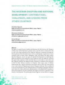
Figure 2.7: Different allocation cases for the 6 MHz band [1] Figure 2.7 shows only a few examples of how the 6 MHz band can be allocated. The entire band is divided for an entire HDTV programme and data services (first example), or an EDTV programme alongside a SDTV programme and data services (second example), or a set of up to four SDTV programmes and data services. The final form is up to the broadcaster and the country’s policies on band administration. For instance, in Brazil, even though ISDB-Tb allows transmission of several SDTV programmes, it depends on the government’s policies whether the transmission of multiple programmes will be allowed or not for private entities. The transmission layers of the ISDB-T standard were improved by implementing the BST-OFDM modulation for transmission, as an evolution to OFDM, in order to achieve greater robustness. The coding layer remained using the current Reed Solomon code used in ISDB-T [1].
2.4.2 Ginga The Ginga middleware is the product of the Brazilian research centres’ efforts in the digital television research; it is a middleware capable of allowing the execution applications in both declarative and procedural programming languages. The middleware can be divided into three different modules: the Ginga Common Core (Ginga-CC), the Presentation Engine (Ginga-NCL) and the Execution Engine (Ginga-J). Figure 2.8 shows in detail the architecture of the Ginga middleware. Figure 2.8 is, in fact, an implementation of the recommendation by the ABNT 15606-1 standard [13] shown in Figure 2.9. The application environment structure recommended in the ABNT standard [13] considers how the whole system, based in the middleware, should function. There are a Hardware and an Operating System layers beneath the middleware. Then it proposes a lower middleware layer with the basic services such as Network, Service Information, Events, Video, etc. over which the Presentation and Execution Engines will be running.
Chapter 2 - Theoretical Review
19
Figure 2.8: Ginga Middleware Architecture [2]
Figure 2.9: Application Environment Structure [13] The Ginga middleware architecture shown in Figure 2.8 focuses on both layers of the middleware. It shows the lower layer as the Ginga Common Core which, besides the services mentioned earlier, also hosts the media player’s APIs and the Java Virtual Machine (JVM). The JVM is an essential element for the Ginga-J Execution Engine, as Ginga-J is entirely based in executing applications on top of the JVM. The top layer of the Ginga middleware is also described in detail. Firstly, the most important element, besides the Presentation and the Execution Engines, is the bridge between them. This
Chapter 2 - Theoretical Review
20
bridge is a form of interface between Ginga-NCL descriptive applications and Ginga-J procedural applications, where one can have access to variables and data from the other [2]. The Presentation Engine is also called the NCL Formatter (since it works with Nested Context Language, NCL), as a declarative language. It is responsible for the processing of NCL descriptive documents, that can alter the way to display a particular programme, adapt the content depending on user interaction and has many more functionalities [1]. The NCL Formatter also includes modules for XHTML, which supports Cascading Style Sheets (CSS), and an ECMAScript interpreter; and a Lua programming language engine. This Lua engine provides support for procedural scripts (based in Lua language) without the use of an Execution Engine and provides pure NCL with the ability to manipulate variables via procedural code [1]. The Ginga middleware supports NCL and Lua as its official languages due to their lower resource demands. Ginga-J requires a better hardware for it to function properly, since it requires more CPU and RAM memory to support the Java Virtual Machine. Originally, Ginga-J was not going to be part of the Ginga middleware, because, to be a viable option, the Ginga middleware had to be royalty-free. Since Java was property of Sun Microsystems (now Oracle), the SBTVD forum signed an agreement with Sun Microsystems to fully develop the Ginga-J specification entirely based on open standards [14]. This allowed Ginga-J to be considered official as well, although many entry-level interactive set-top boxes do not support it yet. The Ginga middleware is also conceived as the interface between the content providers and the interactive devices in mobile devices, such as cellphones and Personal Digital Assistants (PDA). Since providing interactivity to mobile devices is one of the main objectives of the Ginga middleware, it becomes apparent that, besides data transmission, it is important that Ginga offers reception and data interpretation for different devices [1]. Figure 2.10 shows the interactivity context for Gingabased devices. Figure 2.10 illustrates the features of the Ginga middleware for Ginga-compatible devices. The Ginga devices must be able to receive any type of broadcasted TV signal (via radio waves, cable, satellite, IPTV, etc.) and be able to display the media as well as deliver the interactive applications and data to the users if the devices support interactivity. Also, the Ginga-based devices must be able to receive and interpret user events and send them to the content providers via a return path [1].
Chapter 2 - Theoretical Review
21
2.5 Interactivity So far it has been mentioned that interactivity is a prime feature of digital television. The whole concept of watching television, and its advantages will be revolutionised with interactive television (with applications such as T-Government, T-Banking, T-Learning, etc.). However, it has yet to be defined what interactivity is, and how does it work in the Ginga middleware-based ISDB-Tb. To be interactive, according to the Merriam-Webster English dictionary and Encyclopædia Britannica, is defined as follows: “Interactive adjective: involving the actions or input of a user; especially of, relating to, or being a two-way electronic communication system (as a telephone, cable television, or a computer) that involves a user’s orders (as for information or merchandise) or responses (as to a poll).” [16] This definition is accurate for the interactivity requirement that digital television has: it needs a middleware able to be a bidirectional system that answers to user interaction and communicates with the content provider. However, full interactivity is often confused with a system that a user interacts with, yet it does not send data to a content provider to display customised content. This is called local interactivity, and it is the very basic form of digital television interactivity, where the user is not required to exchange information with the broadcaster after the download of the interactive application. The digital television requirement for full interactivity demands a return path to the broadcaster or content provider. This standard requirement is translated into a technological requirement: the TV sets and Gingaenabled devices must support interactivity and must provide at least one form of return path [6]. This represented a great problem for low-cost digital television: Ginga enabled TV sets were scarce
Figure 2.10: Interactivity Context for Ginga-based Devices [1]
Chapter 2 - Theoretical Review
22
and very expensive a few years ago. Even today they are not as cheap as for everyone to acquire one. Therefore, the set-top box came out as a viable low-cost alternative. These set-top boxes allow any TV set to display and provide interactivity at a low cost (specially in countries where the government sets subsidies for STBs to promote the inclusion of digital television). Figure 2.11 illustrates a generic interactive digital television system based in set-top boxes.
Figure 2.11: Model of interactive digital television system [6] There are three levels of interactivity defined for digital television: in the basic level, as seen before, the user is not required to exchange data with the broadcaster with applications such as the noughts and crosses game (better known as tic-tac-toe in the United States and as Jogo da Velha in Brazil). Then, a deeper level of interactivity is required when there is a need of data exchange from the user to the broadcaster (unidirectional). This is the case of a classic poll interactive application, such as the voting system for reality shows. Finally, the highest level of interactivity is defined by having a full dedicated bidirectional channel between the user and the broadcaster. A good example for this is, perhaps, the t-banking applications where user data is confidential and must be sent through a separate channel for security reasons [6]. One important factor about interactivity is that, even though the broadcaster can send the interactive content (the application, not the data) through the broadcast channel, it is not mandatory; the broadcaster may choose to send the interactive content via interactive channel as well. ISDB-Tb sets a maximum data rate of 20 Mbps per channel for interactive data and services via broadcast network [6]. This is a very important factor in the design of applications, as will be seen over the
Chapter 2 - Theoretical Review
23
next chapters.
2.5.1 Interactive Services Some of the interactive services available (or soon to be available) for digital television in Brazil are [6]: • Electronic Programming Guide (EPG): It is a menu that allows the user to have information about the programming of several channels at the same time, and allowing to change the channel accordingly.
Figure 2.12: Example of an EPG [1]
• Enhanced Television: it is basically the same interactive television that once existed (such as reality show voting), only without the need for the user to reach another medium in order to use the interactivity (like sending SMS messages from their cellphones to vote, and voting directly on the TV instead). • Web Browsing: this service allows the user to browse the web via a Ginga-NCL or Ginga-J web browser application. • Interactive Commercials: Commercials can increment their detail levels by offering information about the products on demand, and even offer the user to purchase products directly on TV.
Chapter 2 - Theoretical Review
24
2.6 MPEG-2 Transport Stream The ISDB-Tb standard, as well as ISDB and DVB, utilises the MPEG-2 Transport Stream to multiplex and broadcast the audio, video and data signals. This section presents a brief description of the MPEG-2 Transport Stream. Whenever it is spoken about MPEG, it is usually referring to compression and quality of video. The MPEG-2 standard goes beyond that scope, and the MPEG-2 Transport Stream and Program Stream define the ways the MPEG-2 content (audio/video/data) is delivered [17]. It is important to note that the MPEG-2 Program Stream is a way of storing content (such as a media file in a computer) while the Transport Stream is made for transmission (even though some transmission software allows multiplexing in Program Stream). The Transport Stream is more appropriate for transmission since it is more robust (and less prone to errors), and can allow one or multiple content channels inside. This is specially useful for Cable operators that provide content via satellite, since they have to send every channel through the same Transport Stream [17].
Figure 2.13: Simplified Model of the MPEG-2 Transport and Program Stream Multiplexing [9] Figure 2.13 shows a simplified model of the MPEG-2 multiplexing scheme for Transport and Program Streams. Both the audio and video raw data signals are encoded using an appropriate encoder (in ISDB-Tb’s case, MPEG AAC and h.264 respectively). After the audio and video are encoded, they pass through a packeting process (part of the MPEG-2 specification) and are converted into Packetised Elementary Streams (PES). These PES (audio, video and data) are then multiplexed
Chapter 2 - Theoretical Review
25
together by the Transport Stream Multiplexer (since this dissertation is about broadcast terrestrial television, the Program Stream will be discussed no further, as it goes beyond the scope of this section). The bit-stream of the MPEG-2 Transport Stream packet is described in Figure 2.14. Each packet contains 188 bytes, with 184 bytes of payload and the other 4 bytes of header [17].
Figure 2.14: TS Packet Structure [18] The PID, or Packet Identifier, is a 13-bit key that is part of the 4-byte header of the TS packet, as shown in Figure 2.14. It associates each PES with the TS packet by assigning the same PID number to each of the same PES packets (for instance, all audio packets of the same audio stream will have the same PID number). When no video, audio or data PES packets are available, the TS Multiplexer uses TS packets with no PID as a form of buffer control to maintain the bit-rate constant [8, 17, 18].
2.6.1 DSM-CC Protocol and Data Carousel The DSM-CC (Digital Storage Media – Command and Control) protocol, was developed as part of the MPEG-2 Standard [9] as a way to control the video flow of video-on-demand servers in a network. It was defined in MPEG-2 (ISO/IEC 13818-6) part 6, and represents a series of methods to provide additional functionalities for later multimedia technologies to come. The original concept of DSM-CC was focused on a network-based utilisation, where the media objects would be inside the network, and users could request content on demand. However, for the current digital television scheme, users are not able to request media to the content provider. To overcome this difficulty, DSM-CC retransmits every object of the transport stream in a cyclic way, hence the name Carousel. The carousel is a method of transmitting DSM-CC segments in a repeated routine, allowing digital television receivers to access the media at any time. The DSM-CC protocol specifies exactly how the data carousel should operate, how data should be transmitted, stored, etc. The following section presents the metadata tables contained in the
Chapter 2 - Theoretical Review
26 transport stream, specified by the DSM-CC protocol.
2.6.2 Metadata Tables The MPEG-2 Transport Stream is based on several metadata tables, called Program Specific Information tables (PSI). These tables structure and organise which packets belong to which service and which programme. The PSI tables is divided into five different tables, each with its own Packet Identifier (PID) and functions: • PAT (Program Assosiation Table): in charge of keeping track of the programmes and their associated PID numbers. • CAT (Conditional Access Table): it is accessed only when the TS is scrambled for security purposes. • PMT (Program Map Table): associates the PID of the elementary streams with specific types of services. • NIT (Network Information Table): contains information regarding the channel frequencies and other transmission channel related aspects. • TDT (Time and Date Table): provides the date and time for the receivers to set their local time and allow synchronisation with the EPG. This chapter focused on defining the main concepts about middleware, the specific Ginga middleware, interactivity, and the way the content is transmitted through the MPEG-2 Transport Stream. The following chapter will now introduce the development tools and environments for Ginga-NCL and describe how NCL and Lua languages work for Ginga.
Chapter 3
Programming Languages and Development Tools for Ginga
S
ince the beginning of the studies in Brazil to improve ISDB-T, the major research centres focused a great amount of resources in the Ginga middleware development. However, some of the research was also focused on how to write and deploy applications. This chapter
introduces the reader with the concepts of Nested Context Language and the NCLua API and then gives an overview on the current (and outdated) development tools and environments.
3.1 Nested Context Model The Nested Context Language is a declarative language based in the Nested Context Model (NCM) [19]. It was chosen by the SBTVD group to be the declarative language for the Brazilian digital television system. This section will describe the structure of the Nested Context Model and then explain the elements of the Nested Context Language.
3.1.1 NCM Elements The NCM is based in the context of nodes and links. The nodes contain information (such as media objects) and the links stablish the relationships between them. Each NCM-based application is an Entity, and each Entity has properties and elements. Figure 3.1 shows a basic NCM structure. 27
Chapter 3 - Programming Languages and Development Tools for Ginga
28
Figure 3.1: Overview of NCM class hierarchy [19]
The essence of the NCM-based application is the Entity. It represents itself and the entire context where it is executed. The Entity has different elements, as shown in Figure 3.1. The basic elements of the Entity are the Descriptor, the Connector, the Link and the Node (DescriptorSwitch is a type of descriptor that allows multiple scenarios for media display, as will be explained further in this section). The Node is the most important element of the Entity. There can be many nodes existing at the same time, and each of them contains some sort of information. It is also called an NCM object, and is composed of an identifier, its content (the information per se), and a set of anchors [3]. It is important to mention that NCM is a structure-based model and not a media-based one (like XHTML) [3, 19, 20]. This means that the programming will be independent of the contents of the nodes, since the model operates on relationships between nodes and not between media. However, this does not mean that NCM disregards the types of media; on the contrary, it classifies each media node in subclasses depending on the type of media contained by the Node (i. e. text, image, audio,
Chapter 3 - Programming Languages and Development Tools for Ginga
29
video, Lua objects, Java objects, HTML objects, etc.). Nodes are classified by their specialisation: nodes containing media are called media nodes, or content nodes. However, two other types of nodes as well: the composite nodes and the context nodes. The composite nodes are those whose contents are a combination or composition of several content nodes. These types of nodes are important, as they allow creation and adaptability of content in time by combining different types of content nodes. The other kind of node is the context node. It is a type of composite node that contains various content or context nodes, defining a context where one or more nodes will interact according to Descriptors. The advantage of context nodes relies on creating independent multi-node processes that can be triggered by a single starting point (the context node itself) [3]. The anchors, which are part of the Node, are properties that describe how the Node will display its content. For instance, in a media node that contains a video, an anchor could be a property that defines a segment of the video (from time 01:03 to 01:10, for example). Since NCM is structuredbased, as mentioned earlier, the anchors are completely independent of the content, and are defined separately as well. Besides the Node, the other elements of the NCM entity are the Descriptor, the Connector and the Link. In a general way (disregarding, for now, how the nodes operate between themselves), a Descriptor is a property of the NCM entity that rules how a node will be displayed (where and when). It has the capability of assigning certain region of the screen, and can decide when it will be displayed (space-time synchronisation) [20]. Following the Descriptor, the Connector is a key element as well, since it creates roles and bindings to rule the program flow. It designs the state machine defining each state and how the program will go from one state to another. Finally, the Link element will place in motion the Connector’s rules. It is in charge of assigning those roles and bindings to the nodes, so that they obey the designed state machine [3]. The Entity’s elements have been described so far, and how they relate with each other. However, the relationship between them does not depend exclusively on the Entity’s elements. As mentioned earlier, the Node has anchors that rule its content’s behaviour. Nonetheless, the Node presents other types of properties that better define itself, as well as its behaviour. These are called Interfaces, and
30
Chapter 3 - Programming Languages and Development Tools for Ginga
are illustrated in Figure 3.2 [3, 19].
Figure 3.2: Interfaces of an NCM Node [3, 19]
The Node’s interfaces may be of different types, depending on its specialisation. Content nodes (or media nodes) are classified by its type of information contained (video, audio, text, etc.), as mentioned before. These nodes have the anchors as interfaces with the Entity. The first type of anchor is the content anchor (or area anchor) whose primary attribute is the region attribute. The region anchor associates a node with an specific context (called region), which represents the whole content of the Node [19]. There is another type of anchor called attribute anchor. This type of anchor holds to a property of the Node, as defined in the Descriptor associated with it. These anchors are the ones in charge of positioning in time and space the presentation of the content of the Nodes [19].
Chapter 3 - Programming Languages and Development Tools for Ginga
31
3.1.2 NCM Events The events in NCM are the behavioural part of the declarative environment. They are the basis of the NCM state machine, and allow NCM-based languages (such as NCL) to define certain states for different nodes, and the presentation can adapt according to the current nodes’ states. The basic events defined by NCM are the following ones [19]: • Presentation Event: it is an event that represents the exhibition of a content node depending on an specific descriptor and an specific situation. This means that different descriptors and different situations may apply for unique Presentation Events. • Composition Event: it is the event that presents the composite map (for emphcomposite nodes). • Selection Event: it is an event, similar to the Presentation Event, that triggers by user input. In the context of digital television, this could be a remote control. • Attribution Event: it is an event that triggers with a node’s specific anchors. Each event has its own state machine as defined by NCM. Each event may have the following states: sleeping, occurring or paused [19]. Figure 3.3 shows a generic NCM event state machine, with the processes involved in changing states.
Figure 3.3: NCM event state machine [19] The life cycle of an event starts at the sleeping state. It will go into the occurring state (after a start trigger) when displaying its content and will stay until any of the following occur: a stop trigger
32
Chapter 3 - Programming Languages and Development Tools for Ginga
(might be the natural end of the media as well) or an abort trigger. The abort trigger will take any state into the sleeping state regardless of the conditions. Besides the occurring state, there is also the paused state as well, that happens whenever the exhibition is temporarily suspended and the event was in the occurring state (this would classify as a pause trigger. A resume or start trigger will return the event to its occurring state. With the Nested Context Model described, the next section will illustrate the relationships between the NCL tags and the NCM elements. Since this thesis focuses on application design rather than low-level NCL description, explaining the NCM in further detail escapes the scope of this thesis. Nevertheless, the already presented context suffices for a good understanding of the NCL language and the reader may refer to [19–21] for more in-depth explanation on the NCM.
3.2 Nested Context Language In this section, the relationships between the NCM elements from the last section and the XML Schemas [22], or tags, from the NCL will be presented in Code 3.1. This code serves the basic structure of a NCL document.
Code 3.1: Sample NCL Code
Chapter 3 - Programming Languages and Development Tools for Ginga
33
The most noticeable aspect of the sample NCL code in Code 3.1 is, perhaps, the fact that it is a XML-based document. NCL is a declarative language based on the NCM model, but following XML schema for compatibility between systems and the Internet [19, 22]. This is shown in the header of the NCL file. The preamble of the NCL document (everything between the and tags) contains the bases for the region anchors (defining position and size anchors for future assigning to content nodes), and for the descriptor and connector elements as well. The tags and represent the environments where the region, descriptor and connector elements reside. In Code 3.1, the regions describe the areas on-screen where the media contents will be displayed; the descriptors assign the “background” and “luascript” media nodes to the regions (actually, the media nodes are linked to the regions via the descriptors); and the connectors define the rules (conditions and actions) to bind the nodes (as components). These bindings and region assigning can be seen clearly in the section of Code 3.1. This section represents the core of the NCL document, containing the ports, contexts, media nodes and the links. The link property of the NCM Entity is present as well, with the tag. The xconnector summons a specific connector defined in the connector base, and applies the rules as bindings to the nodes. This is the way to link nodes and force them to follow the event state machine rules.
Chapter 3 - Programming Languages and Development Tools for Ginga
34
3.3 NCLua API The Ginga middleware consists of a presentation engine and an execution engine, as was mentioned earlier in Section 2.4.2. This does not mean, however, that both the presentation and the execution engines (based in Xlets for Ginga-J) must execute together at all times for an application to be presented. The Ginga-NCL presentation engine offers execution of procedural code by the use of the Lua Player [23]. The Lua Player is an engine that processes NCLua (Lua scripts made for the NCL language) objects (which are the contents of a media node containing the script). It is based on the Lua standard library, and provides the programmer with 5 other modules for content presentation (the NCLua API). Since the Lua language is very well known and has become a standard in video game programming, this thesis will not present the Lua language per se, but rather the NCLua API and its modules. The creator of Lua, Roberto Ierusalimschy, has published the lua.org website containing detailed information on the language, as well as a book with the same contents [24]. The NCLua API include the following modules [23]: • ncledit module: it allows NCLua applications to modify the NCL document. • canvas module: it is the NCLua module for manipulating images and drawing on-screen. • event module: it provides the NCLua applications to communicate with the NCL Player through NCL events. • settings module: it exports a table with variables for the NCLua application to fetch. • persistent module: it presents the NCLua API with variables that persist after the application finishes. These modules are required by the ABNT NBR 15606-2 standard [23] to be included in the Ginga middleware. Unfortunately, current Ginga implementations still lack the ncledit, settings and persistent modules, and only custom implemented middleware (that are not following the standard) have them available. Therefore, the only API modules fully implemented are the canvas and event, which will be key in efficient GUI design. An extensive documentation on the canvas and event module methods for Lua script are presented in [23, 25, 26].
Chapter 3 - Programming Languages and Development Tools for Ginga
35
3.4 Development Tools This section will introduce the development tools used in the creation of digital television interactive applications. Some of the tools are outdated and no longer supported, while others are constantly getting updated and have great community support.
3.4.1 Composer The Composer software is a hypermedia authoring tool developed by the TeleMídia Laboratory from the Informatics Department at the Pontifícia Universidade Católica do Rio de Janeiro, PUC-RIO [27]. This tool, based in Java, presents the programmer with four different views to generate NCL code, as shown in Figure 3.4.
Figure 3.4: Multiple Views of the Composer Authoring Tool [27] Figure 3.4 illustrates the four visualisation modes available for code authoring in Composer:
1. Structural View: Presents the nodes and links, and allows to add media and context nodes, define their properties and stablish the links between them.
Chapter 3 - Programming Languages and Development Tools for Ginga
36
2. Layout View: Presents the regions on-screen where the media nodes will display their content. It allows creation and resizing of the regions and their dimensions and positions by using the mouse. 3. Temporal View: Shows the time synchronisation between the media nodes, and establishes the time anchors for triggering events. 4. Text View: Edits the NCL code and highlights the NCL syntax. One of the most interesting features of Composer is that the four views are synchronised; that is, each time a view is modified, the rest of the views will adapt (hence, auto-generating NCL code). Unfortunately, the Composer authoring tool has been discontinued and is no longer updated [28].
3.4.2 Eclipse The Eclipse Java IDE (Integrated Development Environment) is an open-source software development environment with a great plug-in capability. It originally started as a Java IDE, but it has several plug-ins that allow programming in PHP, C/C++, HTML and many more languages. Eclipse is based on Java, therefore, it is cross-platform and has versions for Microsoft Windows, Linux and Mac OSX [29]. Since it is open-source, the plug-in development is encouraged and very well received by the community. The Eclipse IDE by itself allows project management, syntax highlight and code completion (for Java), and has a message log for warnings and errors in compilation. Plug-in developers have taken advantage of these features to create suitable plug-ins for their specific languages. This is the case of the NCL Eclipse plug-in, developed by a partnership between the Universidade Federal do Maranhão and the PUC-RIO.
3.4.3 NCL Eclipse The NCL Eclipse is a plug-in for the Eclipse IDE aimed at aiding the creation of NCL documents for digital television. Its main features included NCL syntax highlighting, code folding (to hide or show parts of the source code), wizards, auto-formatting, error validation and code completion [30] in its first version (1.0).
Chapter 3 - Programming Languages and Development Tools for Ginga
37
Figure 3.5: Error Validation and Possible Corrections [30]
Figure 3.5 shows the error validation feature (thanks to the NCL Validator independent library, also developed by the same research team). It is able to detect, besides syntax errors, missing fields or empty callbacks. After improvements over versions of NCL Eclipse, there were more features regarding visualisation and media previews implemented. The improved plug-in offered program visualisation, as shown in Figure 3.6. A small tool-tip presents the program visualisation of the regions when hovering over the code, without having to rely on new windows (distracting the programmer from the source code itself).
Figure 3.6: Program visualisation of the element [30]
Up until 2010, based on the download numbers, it could be argued that NCL Eclipse is, maybe, the most used tool for NCL developing [30]. It is a very robust plug-in, and has a very large community that provides feedback.
Chapter 3 - Programming Languages and Development Tools for Ginga
38
3.4.4 Lua Eclipse The other most relevant add-on for the Eclipse IDE is the Lua Eclipse plug-in. This tool provides an environment with code-completion, syntax highlighting, code folding like NCL Eclipse as well. Moreover, it provides an interface for fast debugging using a pre-configured interpreter (since Lua is not a compiled language, but a parsed one, it does not have a compiler, but rather an interpreter). The Lua Eclipse is available at the luaeclipse.luaforge.net website, and it is free as well. It does provide code completion for the standard Lua syntax, but is not prepared for the NCLua modules and their methods (such as canvas and event). Nevertheless, it is really useful for writing NCLua code, and the interpreter can help in debugging and testing the standard Lua parts of the code. For the interpreter plug-in to work, the Lua Interpreter must be installed as well (also free). Figure 3.7 illustrates an example of the plug-in interacting with the pre-configured interpreter.
Figure 3.7: Evaluating Lua scripts using the pre-configured interpreter
Chapter 3 - Programming Languages and Development Tools for Ginga
39
3.4.5 Ginga-NCL Virtual Set-top Box
The Ginga-NCL Virtual Set-top Box is a free STB emulator developed by the TeleMidia Laboratory at PUC-RIO. It is a VMWare Linux virtual appliance running a modified Ubuntu Linux distribution with the most current Ginga-NCL reference implementation. Currently, its most up-todate version is v.0.12.3, released on August 1st, 2011 at the Brazilian Public Software Website (Portal do Software Público Brasileiro) [31]. The user must have installed the VMWare Player (free software) to be able to run the Ginga-NCL Virtual Set-top Box. Figure 3.8 illustrates the interface of the Ginga-NCL Virtual STB in different phases. When booting up, the user is presented with the Linux GNU GRUB (GNU Grand Unified Bootloader) menu (Figure 3.8a), which offers the user with different versions of the STB (differing, basically, in the framebuffer resolution). Choosing the same (or closest possible) resolution to the application to be executed is highly recommended, as lower resolutions might conceal regions or malfunction. After selecting the desired resolution, the virtual machine will boot to the operating system, and, after the boot sequence finishes, the user will be presented with the screen in Figure 3.8b. The figure displays a few tips on how to deploy an application and execute it, and on what input keys are mapped to the remote controller’s buttons. At this point, the SSH (Secure Shell) server and the SFTP (Secure File Transfer Protocol) server are enabled and running. The user can login to the virtual machine via a SSH client and can upload files via an SFTP or SCP client as well. Some of the latest version’s (v.0.12.3) features include resolutions to emulate portable devices; standardisation according to the ITU-T and ABNT standards (multi-device presentation [21]; NCL object transparency, and remote object look-up via HTTP (HyperText Transfer Protocol) and RTP (Real-time Transport Protocol). It also supports playing MPEG-4 h.264 encoded videos and MPEG-1 Layer 3 (MP3) and AAC encoded audio files to simulate an environment. However, it is important to note that in an application to a real target (a set-top box or a Ginga-NCL enabled TV set), it is impossible to send video or audio files according to the standard [32] (since the only way to get those are from the MPEG-2 Transport Stream itself).
40
Chapter 3 - Programming Languages and Development Tools for Ginga
(a)
(b)
Figure 3.8: Ginga-NCL Virtual STB Interface: (a) GRUB Menu (b) Main Screen
Chapter 3 - Programming Languages and Development Tools for Ginga
41
3.5 Related Projects The current digital television scenario has given path to several research groups to contribute to the Ginga-NCL software development, either in the form of programming aids (such as frameworks and developing tools) or in the form of embedded APIs. This section will present the LuaTV API [33], which is a set of extended features for the NCLua API, and two frameworks for application development: LuaComp and MoonDo [34, 35].
3.5.1 LuaTV The LuaTV API was developed by the Universidade Federal de Paraíba (UFPB) and the PUC-RIO research centres. It is an API designed to be embedded and part of the Ginga-NCL specification, providing the users with extended features such as multi-user applications and better mechanisms for UI development, metadata access and security in communications [33].
Figure 3.9: LuaTV API context within Ginga architecture [33] Figure 3.9 shows the context of the LuaTV API in the Ginga middleware. It lies as a Ginga specific service, along with the NCL, NCLua and XHTML APIs. The NCL Formatter has complete access to the LuaTV API, and it is completely transparent, as the access to NCL, NCLua and XHTML is.
Chapter 3 - Programming Languages and Development Tools for Ginga
42
Even though the API is not part of the current Ginga-NCL specification yet, as it is still under improvements and test scenarios, it is worth mentioning that it is based in four different independent APIs: the Widgets, HAN, Metadata and Security packages. This thesis will present the Widgets package, as it is the only package related to GUI design (further information on the LuaTV API can be found in [33]).
Figure 3.10: LuaTV API Widgets Package [33] The LuaTV Widgets package provides three modules as shown in Figure 3.10. The Window module fills a specific canvas with local or remote URL content; the cursor module support pointers (based on images) to be displayed on canvas; and the textinput module provides methods to capture user input text and show it in canvas. These modules are not fully interactive, but are aids in application development.
3.5.2 LuaComp The LuaComp authoring tool was developed as a capstone project for undergraduate studies at the Universidade de Brasília (UNB). It is a Java-based framework for developing interactive NCLua applications, based, in some extent, on the LuaTV API. It was created based on the following criteria [34]: • The use of the tool should not involve much source code alteration. • From the developer’s perspective, it defines clearly the boundaries between NCL and NCLua programming environments.
Chapter 3 - Programming Languages and Development Tools for Ginga
43
• From the designer’s perspective, modifications on one environment should not affect the other one (NCL related modifications must not affect the NCLua environment. • Use XML files as a form of project and repository management. • Allow template creation and reuse. • Provide a What-You-See-Is-What-You-Get (WYSIWYG) development interface. • Ease the on-screen layout design process. The LuaComp tool generates NCL and Lua source code automatically by the use of the tool, and provides the developer with three views (somewhat alike the Composer tool). These views are the structural, layout, and text view. The first view allows the project management, with connections between different files. The layout view is the main view of the LuaComp tool, as it allows the GUI design of the applications in a WYSIWUG style. Finally, the last view (text) displays the source code for fine tuning. Figure 3.11 illustrates three different views of the same application.
Chapter 3 - Programming Languages and Development Tools for Ginga
44
(a)
(b)
(c)
Figure 3.11: Different Views of the LuaComp tool [34]: (a) Structural (b) Layout (c) Text
3.5.3 MoonDo The MoonDo framework was also conceived as a capstone project at the Universidade Federal de Pernambuco (UFPE) for an undergraduate course. It differs to LuaComp as MoonDo provides the user with an embedded framework of GUI classes to be summoned by the Lua scripts, and
Chapter 3 - Programming Languages and Development Tools for Ginga
45
does offer pre-made components to be instantiated as objects. This is a very particular topic in Lua programming, because the Lua language was not conceived to be an object-oriented programming language [35]. MoonDo offers several programming classes with components such as panels, labels, image frames, menus and many others. These classes allow the user to create larger and more complex applications with little care on the maintenance of the variables, as they become self-maintained objects. Figure 3.12 shows a demonstration of the graphic components available in the MoonDo framework.
Figure 3.12: MoonDo Graphic Components [35] This chapter has presented the reader with the concepts of the Nested Context Model to understand the reasons and benefits of the Nested Context Language as the main declarative language for the Ginga middleware. Besides that, the NCLua has been presented with its current modules to demonstrate a complete procedural environment outside of Ginga-J. Finally, a variety of development tools have been presented, as well as some related projects to this thesis. However, all of the related work presented focus on aiding the programmer to develop faster and easier his or her applications. The following chapter introduces the proposal of this work: a method to design efficiently graphic applications.
46
Chapter 3 - Programming Languages and Development Tools for Ginga
Chapter 4
GUI Design Techniques and Guidelines
O
ne of the most appealing features of digital television is, without doubts, interactivity. Interactive television brings an entire new form of connectivity for spectators; actually, they stop being just spectators and become active agents in their own experience with
television. Interactive applications such as T-Government or T-Banking sound very promising and will integrate a great part of the Brazilian population which currently doesn’t count with an Internet connection at home, as social inclusion was part of the requirements for implementing digital television in Brazil [1]. However, the success of the reception of interactive applications from the spectators depends on some very important factors, such as how attractive the applications are for the spectators; how easy and intuitive to use are they; and if the low-end digital television receivers will be capable of loading and displaying the application fast and smoothly. These factors are so critical that the entire success of the application may depend on them; even if the content has great quality, if it is not well presented or simple enough to use, it will just plummet. Moreover, the situation is even more critical, in this particular moment in time, since interactivity in digital television is just starting to emerge. If the spectators find interactivity a nuisance, they will most likely not want to try new (and more efficiently designed) applications in the future, which would drastically slow down –or even kill- the acceptance of interactive television. This work proposes the concept of efficient graphic user interface (GUI) design as the process of creating aesthetically attractive, simple-to-use, and lightweight graphic user interfaces for interactive applications for digital television. 47
Chapter 4 - GUI Design Techniques and Guidelines
48
Nowadays, most literature on user interface (UI) design is based on computer UI design; that is, design for applications that will be displayed in a computer’s screen. This is called a 2-foot UI design approach (as the average distance from the user to the monitor is 2 feet, or approximately 61 cm), and it focuses on showing plenty of information with small elements to take better advantage of the high display resolution. The average distance from an spectator to a TV set, considered an across-the-room distance, is 10 feet (or roughly 3 metres). Thus, UI design for television is often called 10-foot UI design. Nevertheless, there are UI design concepts that apply for both 10-foot and 2-foot design approaches, focusing on intuitive learning of new interfaces, simplicity of usability, visual clarity and some other elements. Section 4.1 will cover this topic in detail. Most of the techniques proposed in this work are aimed at universal UI design (for both 10-foot and 2-foot viewing distance, and even for mobile devices). There are, however, a few techniques exclusive for 10-foot UI design. Section 4.2 will present a set of conceptual and practical techniques and guidelines for interactive UI design.
4.1 Principles of UI Design The ultimate purpose of graphic design is to communicate a message [36]. However, it is not a simple task at all. A user interface designer must take into consideration many factors, constraints and criteria from the moment of the conception of the idea until the final details. Before beginning the design process, the designer must try to answer the following questions: 1. Who is the application targeted to? 2. What level of interactivity will be required? 3. What is the objective of the application? These questions may define the entire style of the application, as well as its design process, functionality and complexity.The first question is, perhaps, the most essential of all. Having information such as age group, gender, education level, etc. about the target audience is fundamental in the
Chapter 4 - GUI Design Techniques and Guidelines
49
design process. There are studies entirely focused on user reception on interactive user interfaces for television based in age group segmentation [37].
4.1.1 Target Audience The hypothesis of these studies is that consumer product UI (such as digital television) design is completely different from software UI design, and therefore it is not appropriate to target it to experienced users. The research made by the Samsung research centre in Korea on American participants gathered test subjects from two different age groups: kids (ages 8 to 13) and elderly (ages 54 to 62). The test included an interview with the tests subjects on how they learned to use an specific set of interactive applications, Internet TV usage patterns, favourite feature and interface visual attribute comparison [37]. The result shows that neither the kids nor the elderly groups liked to be segmented into stereotypes. They, however, showed responses likely to be expected from their age groups. The kids showed great learning capacity, easily penetrating complex visual displays. They didn’t show concern on making mistakes either, but their interest dropped very fast if the interfaces weren’t visually stimulating (they prefer pictures and animations to keep them interested, as well as cheerful and bold colours). Regarding the input device, the kids showed problems with the overall size of the remote control, since their hands are relatively small and the interaction demanded them to constantly extend their main control finger. Figure 4.1 shows a picture of the remote control used for the tests.
Figure 4.1: Remote Control for User Perception Tests [37] The elderly, on the other hand, were extremely sensitive to colours. They prefer the interface as
Chapter 4 - GUI Design Techniques and Guidelines
50
simple and clear as possible, and favour white spaces in the design. They also appreciate images, but only when they could be useful. The test results also found that the elderly lost dexterity and showed difficulty in finding the correct buttons in the remote control, mainly because the size of the keys is too small. The problem with remote controls is that there is not one single standardised model only. In SBTVD, however, there is an example of a common remote control to serve as a guideline. However, any remote control must comply the mandatory requirements shown in Table 4.1. Table 4.1: Mandatory Remote Control Keys [13] Item
Function
Full-seg
1
0...9
Mandatory
2 3
Back Exit
Mandatory Mandatory
4
⇐⇒
Mandatory
5
⇑⇓
Mandatory
6
OK
Mandatory
7 8 9 10
VM VD AM AZ
Mandatory Mandatory Mandatory Mandatory
Number Functions Description Numeric functions Interactive function Return Command Exit Command • Left/Right arrow commands shall be passed to Ginga applications • Navigation in receiver’s proprietary graphical interface • Up/Down arrow commands shall be passed to Ginga applications • Navigation in receiver’s proprietary graphical interface • OK command shall be passed to Ginga applications • Confirm Operation Red function Green Function Yellow Function Blue Function
Comments These functions permit: • direct access to the channels • after the middleware appropriates these keys, the applications can use them.
Other possible labels are Enter or Confirm Coloured Function Coloured Function Coloured Function Coloured Function
The interactive application design must contemplate these input keys as mandatory. However, it should also consider the layout of the keys for ergonomic reasons. Figure 4.2 shows an example of a remote control, proposed in [13]. The standard does not specify this particular layout as mandatory, but many manufacturers are basing their designs in the same pattern. The order of the coloured buttons, however, is standard. This can be particularly useful for the kids and elderly groups; the kids like bright colours and would prefer to use them, and the elderly can find the coloured keys without much effort (as for reading the labels from the other keys).
Chapter 4 - GUI Design Techniques and Guidelines
51
Figure 4.2: Example of a Common Remote Control [13]
4.1.2 Constraints and Criteria After dealing with the first, and most important, question, two more questions still remain: “What level of interactivity will be required?” and “What is the objective of the application?”. These two questions are, actually, very related to each other. An application that is meant for information such as extra content on a soap opera (synopses, cast and crew, etc.) should require a basic level of interactivity, as defined in Section 2.5. In the particular case of digital television, the following criteria is critical in UI design [38]:
Chapter 4 - GUI Design Techniques and Guidelines
52
• With the small screen space available and the large viewing distance, the user interface graphics and elements must share screen space with the TV programme. This requires using large font sizes (compared to the ones used in 2-foot UI designs) as well as reducing and segmenting the content into screen-sized pages. • Although navigation is understandable for displaying more content on a single UI, the users will not tolerate large amounts of navigation done with the remote control. • Digital television interactive applications are not the same as Internet applications. Navigating through hyper-links in a web page may be difficult with the remote control, since it basically offers the keys shown in Table 4.1. • The fault tolerance for television is lower than for a personal computer. Specially in elder people, where watching television has been a passive activity for many years, failing in completing the tasks required by interactivity may lead to frustration. • The programme context must be preserved. Interactivity must be conceived as extra content, and must not interfere with the main TV programme. The designer must also consider the aspect ratio of the screen the application will be displayed on. Nowadays, it is seldom to find a 4:3 aspect ratio TV set in the stores, since the technology has brought to the market the LCD, Plasma and LED displays at very affordable prices for the majority of the population worldwide. These new TV sets are all based in a wide-screen aspect ratio (16:9). The differences between a 4:3 and a 16:9 display are quite significant, specially since high definition displays come only in 16:9 format. Figure 4.3 illustrates the differences between the 4:3 and 16:9 aspect ratios.
4.2 Design Techniques and Guidelines Studies on how to improve and create efficient designs for user interfaces have been going on for quite some time already, albeit not focused on television. Nevertheless, there are some important guidelines –or golden rules, as mentioned in [39]– that were conceived back then and still apply in today’s digital television scenario.
Chapter 4 - GUI Design Techniques and Guidelines
53
Figure 4.3: Different Television Aspect Ratios [36]
4.2.1 The Golden Rules The following guidelines are not meant for blind following but rather for guiding lights for sensible interface design [39]. They are considered golden rules because they apply to many contexts and are not device or technology-dependent. 1. Place users in control of the interface: The user must feel that he or she is in control. Forcing the user to follow the designer’s concepts disregarding this aspect (i. e. an application that doesn’t allow the user to go back in previous choices until completing a series of forms) can be detrimental in the success and reception of the application. 2. Reduce users’ memory load: Although as a play of words, the author would like to present this rule as “Reduce the memory load from the users’ set-top boxes”. In the Brazilian digital television scenario, this is key. The vast majority of homes with access to digital television will have low-end set-top boxes (as they are the least expensive, and probably will be subsidised by the government as a social inclusion policy). Having applications that execute properly in high-end receivers but poorly, if executing at all, in entry-level ones is definitely not going to be well received. 3. Make the user interface consistent: Most users like consistency. It makes their life easier, and that is why they want to watch television. A consistent interface, provides the user with
Chapter 4 - GUI Design Techniques and Guidelines
54
prediction possibilities and, thus, lets the user feel the interface more intuitive.
Placing users in control of the interface As mentioned earlier, the user must feel he or she is in total control and not being forced into any option, dialogue or action. The recommended way to accomplish this is to follow certain principles that allow users to be in control. This next series of items are principles extracted from [39] and adapted to the context of digital television. • Display descriptive messages and text: Use messages and dialogues (the latter only if required) to show the user his/hers available options. The terms used should be understandable by the target audience (see Section 4.1.1) rather than advanced system or developer terms. • Provide immediate and reversible actions: This is a very important aspect of perception of control by the user. A user must be allowed to go back to check his/hers previous options (in case of a multi-screen form, for instance). • Provide meaningful paths and exits: the user must never be in charge of keeping track of how many levels deep into the navigation he/she is going to. The designer must place ways for the user to quickly return to the top-level menu (escape keys), to change layout, etc. Besides that, it is important no to restrict the user in the ways he/she will navigate between different screens (even though it makes sense, restricting the user by forcing him/her to go from screen 1 through screen 2 in order to get to screen 3 can make it frustrating in slow-responsive set-top boxes). Besides placing the user in control, the designer must also consider reducing the memory load of the total application and creating consistent applications. The following sections will present concepts that deal directly with these issues.
4.2.2 Grid-based design Grid-based design is one of the pillars of effective information systems [36]. Grids are the core of any visual design that is to be perceived as effective, as they promote consistency and predictability,
Chapter 4 - GUI Design Techniques and Guidelines
55
which are very important aspects for efficient design, as was mentioned in Section 4.2.1. The grid aids the user in finding information and resources in the expected place every time. Karyn Lu, at the Georgia Institute of Technology, mentions some practical features that grids offer [36]. The first and most important feature is repeatability. One of the most important aspects valued by users is the ability to find material in the expected place. Repeatability gives the user this element of predictability and consistency, and can be achieved, for example, by maintaining layouts similar in multi-page designs or by giving several single-page designs certain look or style to give the appearance of unity or “Corporate Identity”. Besides that, Lu considers that the purpose of graphic design is delivering the message. The grid brings positive communicative aspects such as, finding information elements in the same place and rely on the designer to deliver important information that requires more attention by arranging these information elements in different spaces, or varying the font size and type (in case of text elements). Figure 4.4 shows an example of a grid-based UI design. Figure 4.4a illustrates the displayed application for the user while Figure 4.4b shows the same image in the designer’s view, with the grid enabled to demonstrate its application.
56
Chapter 4 - GUI Design Techniques and Guidelines
(a)
(b)
Figure 4.4: An Example of Grid-based Design: (a) Presented View (b) Design View (showing grids)
Chapter 4 - GUI Design Techniques and Guidelines
57
4.2.3 Gestalt Laws Having grids enables to align UI objects and distribute them in a tidy fashion. However, the definition of tidy may vary according to different people and their perception of order. Several psychologists around the world who study visual perception, specially for computer interface designs, base their studies in the Gestalt Theory to achieve effective visual results [36, 40]. The Gestalt Theory emphasises that people perceive objects as well-organised patterns rather than independent discrete parts [36]. Generally, the Gestalt Theory is presented as a set of laws uniformly applied by all designers. However, not all designers apply all the laws, and literature usually shows a subset of the total number of laws. According to Chang [40], eleven laws can be identified as principles for effective design. 1. Law of Balance/Symmetry. This law states that a visual object will appear as incomplete if the object is not visually balanced or symmetrical. Figure 4.5a illustrates a visually balanced picture while Figure 4.5b displays visual imbalance.
(a)
(b)
Figure 4.5: Gestalt Law of Balance/Symmetry: (a) Balance (b) Imbalance 2. Law of Continuity: Objects in a line are more likely to be perceived as members of a whole, as the eye’s instinct is to follow the line pattern. Figure 4.6 illustrates three starting points converging into point X. The elements in the segment AXB appear to belong to one group, and the elements in CX appear excluded, as they break the continuity of segment AXB. 3. Law of Closure: Open shapes give the impression of incompleteness. Thanks to the great complexity of the human mind, though, the user tends to complete the images or patterns. This distracts the user and dissipates his/hers attention. Figure 4.7 shows the word “GINGA” disturbed by an interrupted pattern.
Chapter 4 - GUI Design Techniques and Guidelines
58
Figure 4.6: Gestalt Law of Continuity
Figure 4.7: Gestalt Law of Closure 4. Law of Figure-Ground: Different foreground and background colours can completely change the perception of the image. For instance, Figure 4.8a, with a white background, shows a vase while Figure 4.8b is the same picture with a black background and a white foreground, showing two faces.
(a)
(b)
Figure 4.8: Gestalt Law of Figure-Ground: (a) Vase (b) Two Faces
5. Law of Focal Point: The focal point is the centre of interest of a particular visual presentation. Whenever a particular shape or form out-stands among other elements, it is due to draw more attention, as can be seen in Figure 4.9.
Chapter 4 - GUI Design Techniques and Guidelines
59
Figure 4.9: Gestalt Law of Focal Point 6. Law of Isomorphic Correspondence: The images do not represent the same ideas to everyone; most of any individual’s perception comes from that individual’s past experiences. For example, if the icon in Figure 4.10 were to be seen in a computer screen, even though a user might not know Greek (and the Greek word βoηθεια, meaning “help”), the user might understand the concept by associating the question mark with the concept of “help” from previous experiences.
Figure 4.10: A Help Icon
7. Law of Prägnanz (Good Form): A simple design or symmetrical layout gives a concept of well organised. Chang presents an example based on the IBM company logo [40] in Figure 4.11. 8. Law of Proximity: This law states that objects placed near each other appear to belong to a group. Figure 4.12 shows an example of a 12-element arrangement. The human mind perceives this arrangement three horizontal rows.
Chapter 4 - GUI Design Techniques and Guidelines
60
Figure 4.11: Gestalt Law of Prägnanz (Good Form): IBM Logo [40]
Figure 4.12: Gestalt Law of Proximity: Three Horizontal Rows 9. Law of Similarity: Chang also states that similar objects tend to be counted as the same group. This is a technique used to draw the user’s attention. In Figure 4.13, the user can recognise the triangle inside the square because its elements look similar and, thus, appear to belong to the same form.
Figure 4.13: Gestalt Law of Similarity: Triangle inside a Square
10. Law of Simplicity: A graphical message can be better understood if it is presented as simple as possible. However, a complex and ambiguous message may have unexpected results when trying to simplify it. For instance, an e-learning application that tries to teach about astronomy and the southern cross may have better results presenting Figure 4.14a then the cluttered Figure 4.14b.
Chapter 4 - GUI Design Techniques and Guidelines
(a)
61
(b)
Figure 4.14: Gestalt Law of Simplicity [40]: (a) Southern Cross (b) Southern Cross and other Stellar Objects 11. Law of Unity/Harmony: Related objects that appear to have any visual connection are felt as belonging together. If the related objects do not appear to be within the same form, they will be perceived as unrelated by the user. Figure 4.15 illustrates two examples of unity and non-unity in visual presentations.
(a)
(b)
Figure 4.15: Gestalt Law of Unity/Harmony: (a) Unified Visual Presentation (b) Non-unified Visual Presentation Taking into consideration these principles into the design process can help in creating user interfaces that are more aesthetically pleasing, functional and efficient. The Gestalt Laws described earlier can be applied to the user interface design for any device, as they are general guidelines and not device-specific ones.
4.2.4 Colours and Transparency Colours have a very important role in aesthetics and functionality. Besides their organisation benefits (using colours to organise the content will make it easier for the user to find and use the resources available), they also aid in the structure and clarify ambiguity between visual elements [36].
Chapter 4 - GUI Design Techniques and Guidelines
62
Human perception of colours is a very subjective topic which requires extensive studies to understand. However, Lu states that colours such as blue and green (also called cold colours) are unobtrusive and low-key effect, making them suitable for background colours to provide a quiet and calm framework. On the other hand, colours like red and orange (warm colours), have cheerful and activating effects. They should be used with caution, since they are dominant and loud [36]. Besides the choice of colours, the designer counts with a great feature when designing for Ginga-NCL: transparency. The Ginga-NCL player supports transparency for every object, allowing the designer with the possibility of presenting more than one content or idea in the same screen space, at the same time. The use of transparency (in the range of 50-70% opacity level) is highly recommended for content frames, as they take valuable space. As a rule of thumb, if the frame will appear on top of the main TV programme, it should include, at most, an 80% opacity level (100% opacity means 0% transparency). Figure 4.4a displays an 80% opacity level on the frames.
4.2.5 Viewing Patterns The designer can also take advantage of the user’s viewing patterns when presenting information. In western culture, the reading patterns are left-to-right, top-to-bottom oriented; and this greatly influences the way people look at a screen (where they look first, and how they follow). For example, for web pages in a web browser, people tend to follow a “Z” pattern scan as illustrated in Figure 4.16.
Figure 4.16: Typical Page Scanning “Z” Pattern [36]
Chapter 4 - GUI Design Techniques and Guidelines
63
In the case of digital television, there is also a scan pattern designers can exploit. Figure 4.17 shows a viewing pattern for a sample BBCi interactive application.
Figure 4.17: BBCi Viewing Pattern [36]
4.2.6 Safe Areas The designer task is to provide efficient and aesthetically attractive interfaces. So far, it has been mentioned how to achieve functional and attractive designs by exploiting the human perception. However, there are technical specifications that must be considered as well when designing applications for digital television to avoid mistakes. Usually, user interface design assumes that the UI will count on 100% of the screen space and will design appropriately. In TV sets, however, the TV frame may cover from 5% to 7% of the entire perimeter. This means that UI elements in those regions may or may not be obstructed by the TV frame. There are two kinds of safe areas for television. The first one, the action-safe area, is less restrictive, and refers to the area required for the main TV programme to show entirely. However, application graphics and UI must not be based in this action-safe area because elements of the UI close to these borders may not be well perceived. The recommended safe area for UI design is called graphics-safe area, and it is a 10% perimeter area around the screen. Every element inside the graphics-safe area will be well presented, without cut-offs. Figure 4.18 presents the safe areas for UI design.
Chapter 4 - GUI Design Techniques and Guidelines
64
Figure 4.18: Action-Safe and Graphic-Safe Areas for a Wide-Screen (16:9) format TV Screen [36]
4.3 Layout Creation Guidelines This section presents the reader with practical tips to sketch faster and arrive to a full design concept to be implemented in a real interactive TV application.
4.3.1 Sketching the Concept When designing an application, it is very important to define the concept before drawing at all. By following the guidelines described in Section 4.1, and then the techniques mentioned in the last section, the designer will arrive with a general concept. It is imperative that the designer sketches, in paper and by hand, a rough layout of each of the pages (if a multi-page design). When drawing, the grid may be drawn lightly as well to give a sense of order. Figure 4.19 shows a sample sketch for a form application.
4.3.2 Drawing the Interface After the sketching process, the practical part of the graphic design begins. There are several commercial software for image editing, such as Adobe Photoshop, Adobe Illustrator, Adobe Fireworks, Corel Draw, Microsoft Paint, etc. This work’s philosophy, as well as the SBTVD’s and the Ginga community’s, believes in open-source and free software. The author recommends the usage of free open-source image editing software, such as GIMP, which was use for all the images found
Chapter 4 - GUI Design Techniques and Guidelines
65
Figure 4.19: Layout Sketch for a Form Application
in this dissertation. Regardless of the software used, the designer should create a drawing consistent with his/hers original concept sketch. Minor modifications may be included, but the designer should not start creating concept using the software, as this defeats the purpose of the sketch. Figure 4.20 illustrates a very basic concept drawn in GIMP.
4.3.3 Marking Coordinates and Dimensions Following the drawn concept, the next step is to mark where each element is positioned, and what dimensions they have. This step is crucial before the implementation of the design into the application, as skipping it would drastically reduce implementation times (since the developer will have to consult the designer or measure him/herself each element). The GIMP image editing software provides a tool for measurements; however, the user can also rely on the rulers for this matter. Figure 4.21 shows a 1280×720 application layout with dimensions and coordinates marked. Note that this marking is only for the developer’s reference and is not part of the application’s artwork.
Chapter 4 - GUI Design Techniques and Guidelines
66
Figure 4.20: Drawn Concept
Figure 4.21: Marking Coordinates and Dimensions
4.3.4 Implementation Finally, after having the concept sketched, then drawn, and then marked all the elements’ dimensions and coordinates, it is time for the implementation. The designer’s primary task ends here,
Chapter 4 - GUI Design Techniques and Guidelines
67
and it is his/her job to wait for a functional demonstration to test the design. There may be some functional flaws not contemplated during the initial sketch design, which might lead the designer to re-evaluate his/her concepts and adapt them as necessary. The developer will then implement this design into the application. In the Brazilian scenario for digital television, the Ginga middleware is the main target for the designs and, thus, two possibilities for implementation arise. Both Ginga-NCL and Ginga-J can benefit from the guidelines and techniques mentioned in this chapter. However, only the Ginga-NCL scenario was tested during this work, since it is less hardware-demanding and the Ginga-J implementations are not yet completely available in entry-level set-top boxes. In order to implement these designs for the Ginga-NCL scenario, the developer must choose (depending on his project), if the graphic elements will reside in the NCL document, or rather inside an NCLua object as an NCL node. Independently of the choice made, the positions and dimensions marked in Section 4.3 are key for creating the corresponding regions (in NCL) or canvas regions (in NCLua), and the static results will be similar. There is one extra criteria that the developer needs to consider though: the size of the application. The Ginga specification sets the maximum transfer rate for MPEG-2 Transport Stream packets, and for data services inside the TS (shown in Table 4.2). Table 4.2: Maximum bitrate values for each type of service [23] Types of Media
Digital Television Service
Data Service
Service Detail
Bit-rate (Mbps)
1080i
21
720p
21
480p
12
480i
11
Multi-Camera
21
----
2.2
As specified in [23], the maximum bitrate for data services (including Ginga interactive applications) is 2.2 Mbps. However, this data rate still includes TS and PES headers, which reduce the effective bitrate for an specific Ginga application. Besides that, the 2.2 Mbps bitrate is a maximum boundary; this means that the broadcaster may choose to utilise that bandwidth in any way, res-
Chapter 4 - GUI Design Techniques and Guidelines
68
tricting even more the available bandwidth for Ginga applications. Even in the hypothetical case of having the entire 2.2 Mbps, without headers, for Ginga application transmission, 2.2 Mbps is 275 KB/s, meaning that it would take around 4 seconds for a 1 MB application. For interactive commercials, each second on air is worth money, and having to wait 4 seconds may not be worth the cost of interactive on air fees (specially considering that the user may tune into the commercial after it has already begun). Therefore, optimising the application size is mandatory. The optimisation of the application to reduce application size relies heavily on the developer, but there are certain tricks the designer can do to aid in the process. One of the largest bottlenecks in application size reduction is the fact that the imagery forms most of it. Removing imagery when possible, and avoiding colour blending greatly reduces application size (while using compression algorithms such as JPEG). Storing the images in JPEG or PNG (Portable Network Graphics) will compress the images, but the compression obtained depends on how many different colours are there. Using flat colours (as shown in Figure 4.20) will achieve great compression. Figure 4.22 illustrates an example, with two 400×400 PNG files (the borders are just for illustration purposes). Figure 4.22a is a flat colour rectangle with 1.1 KB size while Figure 4.22b has blended colour and is 82.1 KB large. This represents around a 1:75 application size reduction ratio just by avoiding blending.
(a)
(b)
Figure 4.22: Flat vs. Blended Colours: (a) Flat Colour (b) Blended Colour The following chapter presents the other great contribution of this work, aimed at optimising application size and memory load reduction while targeting a specific design situation: text input.
Chapter 5
NCLua Contributions
D
eveloping applications for Ginga-NCL is not a trivial task, as it requires knowledge of the ISDB-Tb broadcast system, the hardware limitations of the most popular STBs in the market, and the benefits of both the NCL and the NCLua languages. It is often
discussed in community forums and digital television lectures if the NCL document should be used for its potential, or if it should rather be just a wrapper for a procedural NCLua object. The literature available presents NCL as a great language for digital television interactive application development (along with some NCLua scripts to back it up), but it never emphasises whether the last statement is true. The test applications developed in the writing of this work showed that it is harder to integrate NCLua scripts with the NCL document while trying to execute event-driven processes in NCL with procedural script in Lua, as the developer has to keep track of how each event in NCL execution may affect the Lua functions. Besides that, NCL screen transitions in multi-page applications showed high latency in screen refresh, perhaps as a buffering issue. When executing the exact same screen transition, but implemented as Lua code, the screen refresh was instant and the latency was not perceived. Therefore, all the following work related to developing applications was based on an NCL wrapper document that would only execute the main Lua script, which consisted on the entire application, including the graphic interface implementation. 69
Chapter 5 - NCLua Contributions
70
5.1 Object-Oriented Programming in Lua The Lua language is not an Object-Oriented Programming (OOP) language, or at least it was not conceived with that purpose. However, it is often useful to create self-aware, independent objects that have their own variables and methods. Many OOP languages have the concept of class, which is a template for object creation. Each object is an instance of that specific class with its defined behaviour and properties. In Lua, however, there is not this concept; objects are not based in classes, but are stand-alone and independent. The Lua documentation recommends a metatable-based approach to address object orientation [24], creating a first object as a prototype for other objects (as instances of the prototype “class”).
Code 5.1: Metatable-based Object Orientation Account = {balance = 0} function Account:new(o) o = o or {} -- create object if user does not provide one setmetatable(o, self) self.__index = self return o end
Code 5.1, as an example code, is proposed in [24] as a metatable-based approach to emulating object orientation in Lua. Some of the projects mentioned in Section 3.5, such as LuaComp, base their object orientation in this metatable approach. It has the benefits of having a syntax pretty similar to most OOP languages, such as C++ and Java. Code 5.1 shows the constructor method for the Account class. Creating other methods for the same class has a similar syntax, with the colon symbol to call the method (class:method). Code 5.2, also as part of the example [24], illustrates how to create more methods for the same class.
Code 5.2: Defining Methods function Account:deposit(v) self.balance = self.balance + v end function Account:withdraw(v) if v > self.balance then error "insufficient funds" end self.balance = self.balance - v end
Chapter 5 - NCLua Contributions
71
This approach is suitable for small projects where privacy is not essential. Even though instantiating more than one object from the same class creates one metatable for each object, those metatables are public and accessible from any part of the code. This breaks the privacy concept a class should have (with private and/or protected methods and variables) and, therefore, is not suitable for automatic object generation (as the virtual keyboard in the next section requires). The main problem of having a class with only public methods and variables does not provide scalability for larger programs, or option for multiple developers to work on the same application. For example, if one developer focuses on a particular class, he will not be able to protect his class by giving only public getter and setter methods to the other developers, and will be giving the entire class structure. Code 5.2 illustrates the creation of two methods to alter the balance from an Account object. However, a direct access to the object’s variable is also possible, completely altering the contents of the metatable without any protection whatsoever, as shown in Code 5.3. Code 5.3: Direct Access to Object Variables b = Account:new{balance = 100} b = Account:new() print(b.balance) --> 100 -- b.deposit(v), an instance of the ‘‘class’’ Account:deposit(v), yields the same result as: b.balance = b.balance + v
Nevertheless, there is another way to deal with privacy, albeit not orthodox. The Lua documentation also presents the concept [24], but the rest of the literature does not seem to mention it (perhaps the majority of object-oriented Lua programmers are not in need for privacy). Code 5.4: Alternative Method for Object Orientation function newAccount(initialBalance) local self = {balance = initialBalance} local withdraw = function (v) self.balance = self.balance - v end local deposit = function (v) self.balance = self.balance + v end local getBalance = function () return self.balance end return { withdraw = withdraw, deposit = deposit, getBalance = getBalance
Chapter 5 - NCLua Contributions
72 } end
Code 5.4 shows an alternative for object orientation. The concept relies on storing the information and method callbacks in different tables, one being a local “self” or “this”, and the other as an interface to the outside. The “self” table would be the equivalent to the protected variable environment found in other OOP languages while the interface table would be the public environment. In Code 5.4, all the variables are stored in the local self table. The class methods are also defined as local (so different classes can have the same name for methods, and different objects would not have privacy problems). Finally, the return callback provides access to the public methods to the newly created object. This method was used for the development of the NCLua virtual keyboard presented in the next section.
5.2 NCLua Virtual Keyboard 5.2.1 Conception One of the main contributions of this work is the development of an open-source virtual keyboard based in NCLua. Many Ginga-NCL developers, when discovering the great potential of interactive television and the possibility of user-targeted customisation, were in need of some sort of text input form to capture user information via return path. However, this is no easy task, and demands the developer to focus a great amount of time in designing an ad-hoc text input method. When the author arrived with this problem, the initial thoughts were to utilise the remote controller’s numeric pad as a form of text input similar to a cellphone text input system. However, the set-top boxes used to test this idea did not respond very well to this: the delay was not predictable and depended on the application’s memory load as well (some applications were faster while others were slower). Besides that, the delay between keys was not constant, rendering the method non-viable. The capture of the keys had to be done in NCLua (via events) in order to be able to process the text inside the procedural environment. Having the keys captured in NCL was not viable either, since each key would require its own node, and moving the cursor from a node to another required many links, thus, being inefficient.
Chapter 5 - NCLua Contributions
73
(a)
(b)
Figure 5.1: Virtual Keyboard, version 1: (a) No keys selected (b) ‘M’ key selected The next idea, based more in design and aesthetics rather than functionality, was to create a matrix containing the key values, and a set of images representing keyboard positions with current selected keys. When capturing the arrow keys (for cursor movement), the program would look up in the matrix and load the new corresponding image. Figure 5.1 illustrates the first version of the virtual keyboard design. For the reasons described in Section 4.3, this first version was completely inefficient. Containing an image similar to Figure 5.1b for each key (with colour blending and several colours), the sample application containing the keyboard had a size of 5 MB. Besides that, two out of three set-top boxes hung from the intensive memory load when moving the cursor. These set of problems motivated the author to propose a solution able to overcome these difficulties. Also, besides just overcoming them, the new keyboard should be parametric, enabling any developer to adapt it to his/her own needs. The new proposed keyboard was designed entirely in NCLua, with no external images to achieve a very low application size. It also is packaged in the form of a Lua library that can be included into any NCLua application.
Chapter 5 - NCLua Contributions
74
5.2.2 Class Description The NCLua Virtual Keyboard is based on one single file, keyBoard.lua, and it is based on two different classes: the KeyBoard class and the KbElement class. The complete source code is available in Appendix A, and a complete NCLua sample application is presented in Appendix B. The KbElement class is the basic element of the Virtual Keyboard. It represents a single key, as the KeyBoard class basically creates a matrix of KbElements. The KbElement are presented in Table 5.1 and Table 5.2. Following the description of the KbElement class, Table 5.3 and Table 5.4 describe the attributes and methods for the KeyBoard class.
Table 5.1: Attributes of the KbElement class Type
Name
Description
integer
width
Specifies the width of the KbElement in pixels.
integer
height
Specifies the height of the KbElement in pixels.
integer
x0, y0
Specify the position of the upper left corner of the KbElement in pixels.
string
text
Specifies the text label of the KbElement.
array
font
An array with the form of {string font-face, integer font-size, string font-style}, specifying the font family, size and style of the text attribute (bold, italic, etc.).
string or
BGColour,
Specify the Background and Foreground colours of the KbEle-
array
FGColour
ment respectively. They can be a string (’blue’, ’red’, etc.) with no transparency, a 3-element array (R,G,B) with no transparency, or a 4-element array (R,G,B,α). R, G, B and α are of integer type and have values between 0 and 255.
boolean
border
Specifies whether the KbElement will have a border (with FGColour) or not. Values accepted are true or false.
Chapter 5 - NCLua Contributions Table 5.2: Methods of the KbElement class string KbElement:getText(void)
Returns the text parameter from the KbElement object. void KbElement:config(struct arg)
Sets the object’s self table parameters with the ones in arg. The arg structure must contain the following parameters: width, height, x0, y0, text, font, BGColour, FGColour, border. void KbElement:setColour(string or array colour)
Calls the NCLua canvas:attrColor method with a string or array colour variable. void KbElement:draw(boolean focus)
Using the attributes defined, draws the KbElement in the current canvas by calling the NCLua canvas:drawRect and canvas:drawText methods. The focus argument switches BGColour with FGColour, to give the impression of a selected key.
Table 5.3: Attributes of the KeyBoard class Type
Name
Description
integer
kWidth
Specifies the width of each KbElement in pixels.
integer
kHeight
Specifies the height of each KbElement in pixels.
integer
x, y
Specify the position of the upper left corner of the KeyBoard in pixels.
Continued on Next Page. . .
75
Chapter 5 - NCLua Contributions
76 Table 5.3 – Continued from Previous Page array
content
array
font
Contains the layout matrices. An array with the form of {string font-face, integer font-size, string font-style}, specifying the font family, size and style of the text attribute (bold, italic, etc.) to be passed to the KbElement objects.
string or
BGColour,
Specify the Background and Foreground colours of the KbEle-
array
FGColour
ment respectively. They can be a string (’blue’, ’red’, etc.) with no transparency, a 3-element array (R,G,B) with no transparency, or a 4-element array (R,G,B,α). R, G, B and α are of integer type and have values between 0 and 255.
boolean
border
Specifies whether the KbElement will have a border (with FGColour) or not. Values accepted are true or false.
integer array
currentLayout Specifies the index of the current selected layout in content. keys
Dynamic table containing the KbElement objects. Repopulates itself with the KeyBoard:create method.
integer
currentX,
Specify the current cursor position of the KeyBoard.
currentY boolean
wrap
Specifies whether the KeyBoard will enable cursor wrapping.
Chapter 5 - NCLua Contributions Table 5.4: Methods of the KeyBoard class void KeyBoard:getParams(void)
Debug function. Prints on console every attribute and value from the KeyBoard instanced object. void KeyBoard:config(struct arg)
Sets the object’s self table parameters with the ones in arg. The arg structure must contain the following parameters: kWidth, kHeight, x, y, content, font, BGColour, FGColour, border, currentLayout, currentX, currentY, wrap. void KeyBoard:create(void)
Creates a dynamic table with the dimensions of the current selected layout and fills it with KbElement objects containing the corresponding KbElement text. Each KbElement object’s position is iterated so that they can be drawn side by side. void KeyBoard:printKeys(void)
Debug function. Displays the text attributes of each KbElement object created by KeyBoard:create. void KeyBoard:draw(void)
Using the attributes defined, draws the each of the KbElement objects in the keys in the current canvas by calling the KbElement:draw method.
Continued on Next Page. . .
77
Chapter 5 - NCLua Contributions
78 Table 5.4 – Continued from Previous Page
void KeyBoard:moveCursor(string dir)
Cursor control function. It receives a string from the “press” NCL type event to redraw the current selected key as deselected, and draws the new selected key as focused. string KeyBoard:onPress(void)
It hides focus on the selected key by calling the KbElement:draw method, and returns the content of the current layout at the current cursor position calling the KbElement:getText method for further processing. void KeyBoard:onRelease(void)
Used after the KeyBoard:onPress method, it returns focus to the selected key. The use of both methods in sequence simulates a selection animation. void KeyBoard:clear(void)
Clears the current canvas to transparency.
The area cleared corres-
ponds only to the area used by the current layout.
This method is
called by KeyBoard:nextLayout, and should be used if implementing a KeyBoard:switchLayout method.
Continued on Next Page. . .
Chapter 5 - NCLua Contributions
79
Table 5.4 – Continued from Previous Page
void KeyBoard:nextLayout(void)
Clears the current canvas calling the KeyBoard:clear method, then recreates the keys table with the next available layout in the content table using the KeyBoard:create method. Finally, draws the newly created keyboard by calling the KeyBoard:draw method. integer KeyBoard:getCurrentXY(void)
Returns the current index of the cursor to two different variables. The syntax would be x,y = getCurrentXY(). integer KeyBoard:getCurrentLayout(void)
Returns the current layout index.
The KeyBoard class was conceived as a class so that it can be instantiated having its own private parameters. This allows the user to create more than one virtual keyboard at any time. Thanks to the parametrisation level the class allows, the developer could use this class as navigation tabs, a framework for noughts and crosses, a Sokoban game (would require modifying the KbElement class to accept images besides the text attribute) or any application that requires a visual matrix. One of the benefits of the implementation of the KeyBoard class is the fast layout creation. It has, as attribute, a content array which contains different layout matrices. When the object calls the KeyBoard:create() method (which is not the constructor), it loads up the current selected layout from the content attribute, getting the layout dimensions to dynamically create the matrix containing KbElement objects. Code 5.5 shows the syntax to create a layout content array while Code 5.6 illustrates a multiple layout creation example.
Chapter 5 - NCLua Contributions
80 Code 5.5: Creating a layout content array -- The content table should have the following structure: content = {layout1, layout2, layout3, ...}
-- The layoutX table should have the following structure or similar: layout1 = {} layout1[1] layout1[2] layout1[3] layout1[4] layout1[5]
= = = = =
{’A’, {’G’, {’M’, {’S’, {’Y’,
’B’, ’H’, ’N’, ’T’, ’Z’,
-- Or, preferably layout1 = { {’A’, ’B’, ’C’, ’D’, {’G’, ’H’, ’I’, ’J’, {’M’, ’N’, ’O’, ’P’, {’S’, ’T’, ’U’, ’V’, {’Y’, ’Z’, ’_’, ’
Code B.2: classtest.lua 1
dofile "keyBoard.lua"
99
Appendix B - Sample Application
100
2 3 4
-- Flag for first run of the event firstTime = 1
5 6 7
-- Dims gets Canvas Dimensions canvasWidth, canvasHeight = canvas:attrSize()
8 9 10 11 12 13 14 15 16
letras = { {’A’, ’B’, {’G’, ’H’, {’M’, ’N’, {’S’, ’T’, {’Y’, ’Z’, }
’C’, ’D’, ’E’, ’F’}, ’I’, ’J’, ’K’, ’L’}, ’O’, ’P’, ’Q’, ’R’}, ’U’, ’V’, ’W’, ’X’}, ’space’, ’DEL’, ’[sym]’, ’OK’}
17 18 19 20 21 22 23 24
numeros { {’0’, {’6’, {’_’, {’*’, }
= ’1’, ’7’, ’&’, ’[’,
’2’, ’8’, ’$’, ’]’,
’3’, ’4’, ’5’}, ’9’, ’@’, ’#’}, ’(’, ’)’, ’-’}, ’DEL’, ’[abc]’, ’OK’}
25 26
teclado = {letras, numeros}
27 28 29 30 31 32 33 34
kb1 = newKeyBoard() params = {x = 30, y = 30, BGColour = {75, 116, 169, 150}, --"75,116,169,255", FGColour = {255, 255, 255, 150}, --"255,255,255,255", kWidth = 64, kHeight = 64, border = true, content = teclado, currentLayout = 1, font = {’vera’, 16, ’bold’}, currentY = 1, currentX = 1, wrap = true}
35 36 37
-- Event Handler function keyHandler(evt)
38 39 40 41 42
-- Setting evt.class == ’ncl’ prevents key from getting in here -- (it seems firstTime was not enough) if (evt.class == ’ncl’ and firstTime == 1) then firstTime = 0;
43 44 45 46 47
-- Clear the screen with Transparency. canvas:attrColor(0,0,0,0); --canvas:drawRect(’fill’, 0, 0, canvasWidth, canvasHeight); canvas:clear(0, 0, canvasWidth, canvasHeight);
48 49 50 51 52 53
-- Draw Keyboard kb1.config(params) kb1.create() kb1.draw()
54 55
end
56 57 58 59
-- Only Key Pressing events will go through if (evt.class == ’key’ and evt.type == ’press’) then
Appendix B - Sample Application
60 61
if (evt.key == ’CURSOR_UP’ or evt.key == ’CURSOR_DOWN’ or evt.key == ’CURSOR_LEFT’ or evt.key == ’CURSOR_RIGHT’) then
62
-- If the arrows are pressed, move the cursor. kb1.moveCursor(evt.key)
63 64 65 66
elseif (evt.key == ’ENTER’) then
67
-- Catch the pressed key pressedKey = kb1.onPress();
68 69 70
-- If key was [sym], switch layouts if (pressedKey == ’[sym]’) then kb1.nextLayout(5,4) end
71 72 73 74 75
if (pressedKey == ’[abc]’) then kb1.nextLayout(5,5) end
76 77 78 79
kb1.onRelease();
80 81 82
end
83 84
end
85 86
canvas:flush();
87 88 89
end event.register(keyHandler)
101