require a digital signature to update the no-fly zones so that the system is non-hackable. .... Here, T is a target we want to avoid; the word target comes from .... and we can create a differentiable function l : X â R such that x â T if and only if l(x) ...
Control Algorithms for Soft Walls1 by Adam Cataldo Research Project Submitted to the Department of Electrical Engineering and Computer Sciences, University of California at Berkeley, in partial satisfaction of the requirements for the degree of Master of Science, Plan II. Approval for the Report and Comprehensive Examination: Committee:
Edward Lee Research Advisor
Date ******
Shankar Sastry Second Reader
Date 1
January 21, 2004 Technical Memorandum UCB/ERL M03/42 University of California, Berkeley, CA 94720
1
Contents 1 Introduction to Soft Walls 1.1 Soft Walls . . . . . . . . . . . . . . . . . . . . . . . . . . . . . 1.2 System Model . . . . . . . . . . . . . . . . . . . . . . . . . . .
3 3 4
2 Control from an Implicit Surface Function 2.1 Collision-Avoidance Verification with the Hamilton-Jacobi-Isaacs Approach . . . . . . . . . . . . . . . . . . . . . . . . . . . . . 2.1.1 Verification Methodology . . . . . . . . . . . . . . . . . 2.1.2 The Cost Function . . . . . . . . . . . . . . . . . . . . 2.1.3 Games of Finite Duration . . . . . . . . . . . . . . . . 2.1.4 The Hamilton-Jacobi-Isaacs Approach . . . . . . . . . 2.1.5 Safe Controllers . . . . . . . . . . . . . . . . . . . . . . 2.2 Implementation . . . . . . . . . . . . . . . . . . . . . . . . . . 2.2.1 A Note on Our Dynamics Equation . . . . . . . . . . .
7 7 7 9 13 14 16 16 19
3 Other Soft Walls Control Approaches 21 3.1 Solution for Half-Space No-Fly Zone . . . . . . . . . . . . . . 21 3.2 A Geometric Approach . . . . . . . . . . . . . . . . . . . . . . 28 4 Conclusions and Future Work
2
30
Chapter 1 Introduction to Soft Walls 1.1
Soft Walls
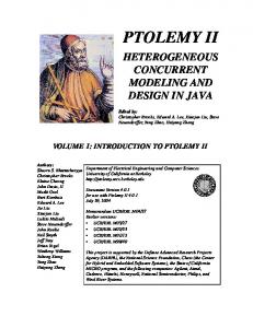
In response to the September 11, 2001 hijackings, Edward Lee proposed a new flight-control technology called Soft Walls [9]. The Soft Walls strategy is to store a 3D database of “no-fly zones”, or restricted airspace, on-board each aircraft and enforce these no-fly zones using an avionics control system. Each aircraft will have its own Soft Walls system. Also, the database will require a digital signature to update the no-fly zones so that the system is non-hackable. Soft Walls is not an autonomous control strategy. That is, the controller does not remove pilot input when the aircraft approaches a no-fly zone. Instead the controller adds a bias to the pilot input, and it never removes all pilot authority. A pilot who approaches a no-fly zone and holds steady will be turned away from the no-fly zone until it is safe to let the aircraft fly straight. A pilot who chooses to turn away faster can do so. A pilot who tries to fly into the no-fly zone will be unsuccessful. Through this, Soft Walls will maximize pilot authority subject to the constraint that no-fly zones are enforced. (The system may also include comfort constraints.) This will give the pilot more maneuverability in an emergency. Figure 1.1 shows how pilot decisions affect the control system. See [10] for some objections to this strategy. Even though Soft Walls is not an autonomous control strategy, it is related to autonomous aircraft control in that it is a collision avoidance problem. This lets us apply collision avoidance techniques similar to those used for
3
pilot tries to enter no-fly zone no-fly zone
pilot holds steady pilot turns away
Figure 1.1: A pilot who approaches a no-fly zone and holds steady will be turned away from the no-fly zone until it is safe to let the aircraft fly straight. A pilot who chooses to turn away faster can do so. A pilot who tries to fly into the no-fly zone will be unsuccessful.
autonomous flight-path planners that keep two autonomous aircraft from colliding. This paper focuses on the collision avoidance algorithms. We consider several controllers we have developed for simulation.
1.2
System Model
We seek a system model that tracks the aircraft’s state as it changes with time. To match reality, this model should depend on the pilot’s actions as well as the actions of the control system we design. We want a general model that does not depend on the particular dynamics of the aircraft. This helps us apply our algorithms to different aircraft. We let [A → B] represent the set of functions mapping A to B, where A meas and B are sets. Then [A −→ B] represents the set of measurable functions from A to B. We then define a system by the tuple S = (I, X, U, U, D, D, f, ξ, X ), in which
4
(1.1)
• I ⊆ R is an interval of time, and t ∈ I is a particular time. We assume that I is a connected subset of R. • X ⊆ Rn is the state space. • U ⊂ Rm , where U is closed and bounded, is the control space. meas
• U = [I −→ U ] is set of control evolutions over the interval of time I. If u ∈ U is a control evolution, and if t ∈ I, then u(t) ∈ U is the control input at time t. • D ⊂ Rp , where D is closed and bounded, is the disturbance space. meas
• D = [I −→ D] is set of disturbance evolutions over the interval of time I. If d ∈ D is a disturbance evolution, and if t ∈ I, then d(t) ∈ D is the control input at time t. • f : X × U × D → Rn is a bounded, Lipschitz continuous function that describes the flow of the system. That is, f (x(t), u(t), d(t)) is the rate of change in state at time t. • C ⊂ 2I is the set of all closed, bounded, and connected subsets of I. If Ω ∈ C, then ∃a, b ∈ I such that Ω = [a, b]. • ξ : C × X × U × D → X is a trajectory. If y ∈ X, u ∈ U, d ∈ D, and [t1 , t2 ] ∈ C, with t2 ≥ t1 , then Z t2 ξ([t1 , t2 ], y, u, d) = y + f (ξ([t1 , τ ], y, u, d), u(τ ), d(τ ))dτ. (1.2) t1
• X ⊂ [I → X] is the set of all state evolutions over the interval of time I. A state evolution x is in X there exists a u ∈ U and d ∈ D such that x(t) ˙ = f (x(t), u(t), d(t)) for all t ∈ I. If x(t1 ) = y for t1 ∈ I, then x(t2 ) = ξ([t1 , t2 ], f, y, u, d) for all t2 ∈ I satisfying t2 ≥ t1 . In Soft Walls x ∈ X is the trajectory of the aircraft. d ∈ D is the action of the pilot, while u ∈ U is the action of the Soft Walls controller. Note that U and D are compact sets. This means that at each time t ∈ I, the control input u(t) and disturbance input d(t) are bounded. These bounds are constraints on the types of inputs the system will accept. These bounds may come from safety constraints or physical limitations of the aircraft. f 5
describes the dynamics equation of the aircraft. The constraints that f is bounded and Lipschitz continuous guarantees that for each initial condition and u ∈ U and d ∈ D, the system S gives a unique trajectory x ∈ X . In this paper, we focus on a particular system S. Here X = R3 . If t ∈ I we let x(t) = (xp1 (t), xp2 (t), xh (t))T represent the state at time t. We define f as xp1 (t) s cos xh (t) f xp2 (t) , u(t), d(t) = s sin xh (t) . (1.3) xh (t) u(t) + d(t) For a picture of the state space, see Figure 1.2.
xp2
xh xp1
Figure 1.2: The state space for the single aircraft is the aircraft’s position (xp1 (t), xp2 (t)) and heading xh (t). We use this model for our Soft Wallscontroller implementation.
Here we assume the aircraft is travelling at a fixed speed s > 0, so the aircraft can only turn or go straight. The input is the rate of change in heading angle. We assume that, due to safety constraints, the aircraft allows a maximum rate of change in heading of M > 0. We will only let the pilot give inputs in this range, so D = [−M, M ]. At each t ∈ I, so that the control input can force the aircraft to turn away from the no-fly zone even if the pilot input commands the aircraft to turn into the no-fly zone, we let |u(t)| > M . So that even when the maximum control input is applied, the pilot still has some authority, we need |u(t)| < 2M . We choose U = [−1.5M, 1.5M ]. We also limit the value of u(t)+d(t) to the range [−M, M ], but we do not include this in our dynamics model. We will explain why in Chapter 2. 6
Chapter 2 Control from an Implicit Surface Function 2.1
Collision-Avoidance Verification with the Hamilton-Jacobi-Isaacs Approach
In this section we present a multi-agent collision-avoidance approach for continuous systems. This is an adaptation of the work of [16] and [15]. We restrict ourselves to nonlinear continuous systems, whereas these papers solve the problem for nonlinear hybrid systems. We use a different information pattern, which we will explain in Section 2.1.1.
2.1.1
Verification Methodology
Given our system S, we now derive a method to generate the unsafe region of the state space X. The target set T is an illegal region of the state space, and a “conflict” occurs at time t if x(t) ∈ T . For Soft Walls T is the no-fly zone. Here, T is a target we want to avoid; the word target comes from missile guidance problems [8]. We let Pre : 2X → 2X be the predecessor function. This function will have the property that Pre(T ), which we call the backwards reachable set of T, is the unsafe region of the state space. Given T , for any control evolution and for each y ∈ Pre(T ), there exists a disturbance evolution which causes a trajectory starting at y to eventually enter T . Trivially, if y ∈ T , then y ∈ Pre(T ). If a trajectory starts outside this subset of the state space, then there exists a control evolution that keeps 7
the state outside of T . We will give a definition of Pre shortly, but we first need some more definitions. We can describe this collision-avoidance situation as a two-player game. Here Player I chooses d ∈ D, and Player II chooses u ∈ U. In Soft Walls Player I is the pilot, and Player II is the Soft Walls controller. We say Player I wins the game if x(t) ∈ T for some t ∈ I. We say Player II wins the game if x(t) ∈ / T for all t ∈ I. The set Pre(T ) is the set of states at which Player I can choose d to guarantee a collision, irrespective of the u Player II chooses. The set X\Pre(T ) is the set of states at which, for each d Player I chooses, Player II can choose u to avoid a collision for all future time. We assume that at each time t Player II knows the pilot’s choice of d(τ ) for all τ ∈ I with τ ≤ t. Player II does not know the value of d(τ ) for τ > t, so we call this a nonanticipative strategy. We also assume that each time t both players know the state x(τ ) for all τ ∈ I with τ ≤ t. For t ∈ I we let Ir : I → 2I be Ir (t) = {τ ∈ I | τ ∈ (−∞, t]}. (2.1) We let the set of nonanticipative control strategies be given by Υ = {γ ∈ [D → U] | d1 ∈ D, d2 ∈ D, ∀s ∈ Ir (t), d1 (s) = d2 (s) ⇒ (2.2) ∀s ∈ Ir (t), (γ(d1 ))(s) = (γ(d2 )(s)}. The information pattern tells us which information available to each player. The information pattern we choose describes the Soft Walls controller, since the system will have access to the pilot’s actions, while the pilot will not be allowed to monitor the control system actions, only the systems effects on the aircraft. In [15], Player I is assumed to be an unknown disturbance, such as wind, the opposite information pattern is used. For more on information patterns, see [1] Formally, Pre(T ) = {y ∈ X | ∀γ ∈ Υ, ∃d ∈ D, ∃τ ∈ (−∞, 0], ξ([τ, 0], y, γ(d), d) ∈ T }. (2.3) We let the avoid function Avoid : 2X → 2X output the safe region of the state space. That is, Avoid(T ) = X\Pre(T ). Lemma 2.1. For all T ⊆ X, Avoid(T ) = {y ∈ X | ∃γ ∈ Υ, ∀d ∈ D, ∀τ ∈ (−∞, 0], ξ([τ, 0], y, γ(d), d) ∈ / T} (2.4) 8
Proof. Avoid(T ) = = = = =
{y {y {y {y {y
∈X ∈X ∈X ∈X ∈X
| ¬(∀γ ∈ Υ, ∃d ∈ D, ∃τ ∈ (−∞, 0], ξ([τ, 0], y, γ(d), d) ∈ T )} | ∃γ ∈ Υ, ¬(∃d ∈ D, ∃τ ∈ (−∞, 0], ξ([τ, 0], y, γ(d), d) ∈ T )} | ∃γ ∈ Υ, ∀d ∈ D, ¬(∃τ ∈ (−∞, 0], ξ([τ, 0], y, γ(d), d) ∈ T )} | ∃γ ∈ Υ, ∀d ∈ D, ∀τ ∈ (−∞, 0], ¬(ξ([τ, 0], y, γ(d), d) ∈ T )} | ∃γ ∈ Υ, ∀d ∈ D, ∀τ ∈ (−∞, 0], ξ([τ, 0], y, γ(d), d) ∈ / T}
Here we carried out negation of a predicate at each step.
2.1.2
The Cost Function
Given our target set, we want a way to compute Pre(T ). Our first step is to rethink how we characterize T . If T is a connected, bounded, open set, and we can create a differentiable function l : X → R such that x ∈ T if and only if l(x) < 0, then we have one such characterization. This will be possible whenever T has a simple shape, like a hypersphere or hypercylinder. We call l the terminal cost function. We then define our cost function V : X × U × D → reals as V (y, u, d) =
inf
τ ∈(−∞,0]
l(ξ([τ, 0], y, u, d)).
(2.5)
As long as l is bounded below, the infimum will always exist. Given a set A ⊂ Ra , we let C n (A) be the set of all functions in [A → R], that has a continuous nth derivative for all a ∈ A. That is � � dn n (2.6) C (A) = g ∈ [A → R] ∀a ∈ A, n g(a) exits da From this point on, we assume l ∈ C 1 (X) and bounded below, and l(y) < 0 if and only if y ∈ T , so that V exists. In this case, V has the following important property: Lemma 2.2. Given y ∈ X, u ∈ U, d ∈ D, V (y, u, d) ≥ 0 ⇔ ∀τ ∈ (−∞, 0], ξ([τ, 0], y, u, d) ∈ /T
9
(2.7)
Proof. V (y, u, d) ≥ 0 ⇔
inf
τ ∈(−∞,0]
l(ξ([τ, 0], y, u, d)) ≥ 0
⇔ ∀τ ∈ (−∞, 0], l(ξ([τ, 0], y, u, d)) ≥ 0 ⇔ ∀τ ∈ (−∞, 0], ξ([τ, 0], y, u, d) ∈ /T Here, we are just applying our definition of V and l. We use Lemma 2.2 to recharacterize Pre(T ) and Avoid(T ). Corrolary 2.3. Pre(T ) = {y ∈ X | ∀γ ∈ Υ, ∃d ∈ D, V (y, γ(d), d) < 0} Avoid(T ) = {y ∈ X | ∃γ ∈ Υ, ∀d ∈ D, V (y, γ(d), d) ≥ 0}
(2.8) (2.9)
Proof. Pre(T ) = = = =
{y {y {y {y
∈X ∈X ∈X ∈X
| ∀γ | ∀γ | ∀γ | ∀γ
∈ Υ, ∃d ∈ D, ∃τ ∈ (−∞, 0], ξ([τ, 0], y, γ(d), d) ∈ T } ∈ Υ, ∃d ∈ D, ¬(∀τ ∈ (−∞, 0], ξ([τ, 0], y, γ(d), d) ∈ / T )} ∈ Υ, ∃d ∈ D, ¬(V (y, γ(d), d) ≥ 0)} ∈ Υ, ∃d ∈ D, V (y, γ(d), d) < 0}
Here we applied predicate negation and Lemma 2.2. Avoid(T ) = {y ∈ X | ∃γ ∈ Υ, ∀d ∈ D, ∀τ ∈ (−∞, 0], ξ([τ, 0], y, γ(d), d) ∈ / T} = {y ∈ X | ∃γ ∈ Υ, ∀d ∈ D, V (y, γ(d), d) ≥ 0} Here we simply applied Lemma 2.2. Now recall that Player I wins the game by causing a collision. In light of Equation 2.8, at each time t Player I should choose d to minimize V (x(t), γ(d), d) and move the state towards the target set until he wins the game. Similarly Player II should choose γ to maximize V (x(t), γ(d), d), so he can keep the state outside of Pre(T ) and win the game. Given our information pattern, Player I will have to minimize V (x(t), γ(d), d) over the worst case choose of γ. In Soft Walls, a malicious pilot will try to minimize V (x(t), γ(d), d), and our controller will try to maximize V (x(t), γ(d), d).
10
We will show how we can use these strategies to compute Pre(T ) in Theorem 2.6. First, however, let V ∗ : X → R be the optimal cost function, where V ∗ (y) = sup inf V (y, γ(d), d). (2.10) γ∈Υ d∈D
We must the existence and uniqueness of V ∗ before we use it. Lemma 2.4. ∀y ∈ X, minz∈X l(z) ≤ V ∗ (y) ≤ l(y). Proof. Since l is continuous and bounded below, and the smallest value occurs when z is in the closed set T¯, minz∈X l(z) exists. V ∗ (y) = sup inf
inf
γ∈Υ d∈D τ ∈(−∞,0]
l(ξ : ([τ, 0], y, γ(d), d)).
≥ sup inf min l(z) γ∈Υ d∈D z∈X
= min l(z) z∈X
Here we are saying that no trajectory can give a value of x which has lower terminal cost than the minimum terminal cost. V ∗ (y) = sup inf
inf
γ∈Υ d∈D τ ∈(−∞,0]
l(ξ : ([τ, 0], y, γ(d), d))
≤ sup inf l(ξ : ([0, 0], y, γ(d), d)) γ∈Υ d∈D
= l(y), Here we applying the fact that inf
τ ∈(−∞,0]
l(ξ : ([τ, 0], y, γ(d), d)) ≤ l(y).
Corrolary 2.5. V ∗ exists and is unique. Proof. Existence follows immediately from Lemma 2.4. Uniqueness follows from the uniqueness of ξ and l and the uniqueness of the inf and sup expressions. Finally, we categorize Pre(T ) and Avoid(T ) in terms of V ∗ .
11
Theorem 2.6. {y ∈ X | V ∗ (y) < 0} ⊆ Pre(T ) {y ∈ X | V ∗ (y) > 0} ⊆ Avoid(T )
(2.11) (2.12)
Proof. V ∗ (y) < 0 ⇔ sup inf V (y, γ(d)d) < 0 γ∈Υ d∈D
⇒ ∀γ ∈ Υ, inf V (y, γ(d)d) < 0 d∈D
⇔ ∀γ ∈ Υ, ∃d ∈ D, V (y, γ(d)d) < 0 We are saying that if V ∗ (y) < 0, Player I can choose d to guarantee a collision. We now apply this to finish the proof of Equation 2.11. {y ∈ X | V ∗ (y) < 0} ⊆ {y ∈ X | ∀γ ∈ Υ, ∃d ∈ D, V (y, γ(d)d) < 0} = Pre(T ) Now we prove Equation 2.12. V ∗ (y) > 0 ⇔ sup inf V (y, γ(d)d) > 0 γ∈Υ d∈D
⇒ ∃γ ∈ Υ, inf V (y, γ(d)d) > 0 d∈D
⇔ ∃γ ∈ Υ, ∀d ∈ D, V (y, γ(d)d) > 0 We are saying that if V ∗ (y) > 0, Player II can choose γ to avoid any future collision. We now apply this to finish the proof of Equation 2.12. {y ∈ X | V ∗ (y) > 0} ⊆ {y ∈ X | ∃γ ∈ Υ, ∀d ∈ D, V (y, γ(d)d) > 0} = Avoid(T )
This theorem tells us that if V ∗ (y) > 0, then y ∈ Avoid(T ), so we can guarantee safety. If V ∗ (y) < 0, then y ∈ Pre(T ), so we cannot guarantee safety. If V ∗ (y) = 0, we need extra information to know if y is a safe or unsafe state. In Soft Walls, this says that if we only know V ∗ , we will need to control the aircraft before it reaches the boundary of the backwards-reachable set, which we call ∂Pre(T ). We now explain how to compute V ∗. 12
2.1.3
Games of Finite Duration
Consider the case where our game starts at some time t < 0 and terminates at time 0. Under this formulation, we will create a cost function we can compute numerically. We first need some definitions. • Pt : 2X × R− → 2X is the timed predecessor, with Pt(T, s) = {y ∈ X | ∀γ ∈ Υ, ∃d ∈ D, ∃τ ∈ [t, 0], ξ([τ, 0], y, γ(d), d) ∈ T }. (2.13) • At : 2X × R− → 2X is the timed avoid function, with At(T, s) = X\Pt. • J : X × U × D × R− → R is the timed cost function, with J(y, u, d, t) = min l(ξ([τ, 0], y, u, d)). τ ∈[t,0]
(2.14)
Note that the we use min instead of inf, because the set [t, 0] is closed, so the minimum will exist. • J ∗ : X × R− → R is the optimal timed cost function, with J ∗ (y, t) = sup inf J(y, γ(d), d, t). γ∈Υ d∈D
(2.15)
By the same reasoning as in the last section, we can show that J ∗ exists and is unique. This gives us Proposition 2.7. Proposition 2.7. {y ∈ X | J ∗ (y, t) < 0} ⊆ Pt(T, t) {y ∈ X | J ∗ (y, t) > 0} ⊆ At(T, t)
(2.16) (2.17)
The proof of Proposition 2.7 is nearly identical to that of Theorem 2.6. We now show that at each y ∈ X J ∗ (y, t) is decreasing as the starting time t decreases. Lemma 2.8. For all t ∈ (−∞, 0] and s ∈ (−∞, 0], with s < t, and for all y ∈ X, J ∗ (y, s) ≤ J ∗ (y, t) V ∗ (y) ≤ J ∗ (y, s) 13
(2.18) (2.19)
Proof. J ∗ (y, s) = sup inf min l(ξ([τ, 0], y, u, d)) γ∈Υ d∈D τ ∈[s,0] � � = sup inf min min l(ξ([τ, 0], y, u, d)), min l(ξ([τ, 0], y, u, d)) τ ∈[s,t] τ ∈[t,0] γ∈Υ d∈D � � = sup min inf min l(ξ([τ, 0], y, u, d)), inf min l(ξ([τ, 0], y, u, d)) d∈D τ ∈[s,t] d∈D τ ∈[t,0] γ∈Υ � � ∗ = min sup inf min l(ξ([τ, 0], y, u, d)), J (y, t) γ∈Υ d∈D τ ∈[s,t]
Thus J ∗ (y, s) ≤ J ∗ (y, t). Here we have broken [s, 0] into the two intervals [s, t] and [t, 0], to prove Equation 2.18. V ∗ (y) = sup inf
min l(ξ([τ, 0], y, u, d)) � � = sup inf min min l(ξ([τ, 0], y, u, d)), min l(ξ([τ, 0], y, u, d)) τ ∈(∞,s] τ ∈[s,0] γ∈Υ d∈D � � = sup min inf min l(ξ([τ, 0], y, u, d)), inf min l(ξ([τ, 0], y, u, d)) d∈D τ ∈(∞,s] d∈D τ ∈[s,0] γ∈Υ � � ∗ = min sup inf min l(ξ([τ, 0], y, u, d)), J (y, s) γ∈Υ d∈D τ ∈−(∞,0]
γ∈Υ d∈D τ ∈(∞,s]
Thus V ∗ (y) ≤ J ∗ (y, s). Here we have broken (−∞, 0] into the two intervals (−∞, s] and [s, 0], to prove Equation 2.18. Not only is V ∗ (y) a lower bound for J ∗ (y, t), it is also a limit point as t →, −∞. This is what we now show in theorem 2.9 Theorem 2.9. For all y ∈ X, lim J ∗ (y, t) = V ∗ (y)
t→−∞
2.1.4
(2.20)
The Hamilton-Jacobi-Isaacs Approach
We know show how to compute J ∗ (y, t) by solving a partial differential equation (PDE). Since this J ∗ (y, t) converges to V ∗ (y) as t approaches −∞, an approximation for J ∗ (y, t) for large, negative t will be a good approximation 14
of V ∗ (y). We will then be able to approximate our backwards-reachable set, Pre(T ). Solving J ∗ (y, t) from PDE requires that J ∗ (y, t) to is differentiable. In practice, J ∗ (y, t) will be continuous but may have “kinks”, or points where the function is not differentiable. These kinks correspond to points where the optimal control is not unique. At all points where J ∗ (y, t) is differentiable, however, it will satisfy our PDE, so we need J ∗ (y, t) to be a general notion of a solution to our PDE. We call this a viscosity solution. A good introduction to viscosity solutions can be found in [6]. Let h : R × R− → R, and let ∇y h(y, t) denote the gradient with respect to y at the point (y, t). Suppose we have a function H : Rn × Rn → R, which we call the Hamiltonian. In dynamics [12], the Hamiltonian represents the total energy of a time-invariant system if the potential energy is independent of velocity. Our notion of the Hamiltonian is more general than this. If g : Rn → R is a continuous function, then a bounded, uniformly continuous function h is a viscosity solution to the PDE ∂ h(y, t) + H(∇y h(y, t)) = 0 ∂t h(y, 0) = g(x),
(2.21) (2.22)
if for all v ∈ C ∞ (R × R− ), 1. if h − v has a local maximum at (y0 , t0 ), then ∂ v(y0 , t0 ) + H(∇y v(y0 , t0 )) ≤ 0. ∂t
(2.23)
2. if h − v has a local minimum at (y0 , t0 ), then ∂ v(y0 , t0 ) + H(∇y v(y0 , t0 )) ≥ 0. ∂t
(2.24)
If a viscosity solution to Equation 2.21 exists, it is unique. At any point (y, t) where h(y, t) is differentiable, it will satisfy the PDE in the ordinary sense. The Hamiltonian which we will use is � � T H(y, p) = min 0, min max p f (y, v, e) . (2.25) e∈D v∈U
15
Theorem 2.10. If J ∗ (y, t) ∈ C 0 (X × R− ), then J ∗ (y, t) is the unique viscosity solution of ∂ ∗ J (y, t) + H(∇y J ∗ (y, t)) = 0 ∂t h(y, 0) = g(x),
(2.26) (2.27)
where H is defined in Equation 2.25. This theorem is very similar to Theorem 4.1 (a) of [5], where we add the min with zero term so that J(y, t) can only decrease with time. While we may not be able to find an analytic solution to Equation 2.26, we can use the method of [13] to solve the problem numerically. This method gives high-accuracy approximations of J ∗ and is able to isolate kinks. This allows us to characterize the safe and unsafe regions of the state space.
2.1.5
Safe Controllers
A safe control strategy γ ∈ Υ will ensure that if the state is near the boundary of the backwards-reachable set, ∂Pre(T ), then the state cannot enter ∂Pre(T ). The optimal control strategy γ ∗ : D × X → U, will always try and move the state away from the reachable set. That is γ ∗ (d, y) = arg inf V (y, γ(d), d)
(2.28)
γ∈Υ
We call the safe set of control strategies Us , where Us = {γ ∈ Υ | ∃� > 0, ∀y ∈ X, V ∗ (y) ≤ � ⇒ ∀d ∈ D, γ(d) = γ ∗ (d, y)} . (2.29) If we assume V is differentiable, a safe controller is one for which on the boundary of Pre(T ), the value of V is increasing. That is, Us = {γ ∈ Υ | ∀t ∈ I, x(t) ∈ ∂Pre(T ) ⇒ ∇V ∗ (x(t))T f (x(t), (γ(d))(t), d(t)) ≥ 0}
2.2
(2.30)
Implementation
We use a two-step process to implement the Soft Walls controller. For the first step, we start with a signed distance function l such that ∀y ∈ X, |l(y)| = min ky − tk. t∈∂T
16
(2.31)
We choose T such that this has an analytic solution, so no computation is involved here. Recall from Section 2.1 that T = {y ∈ X | l(y) < 0} and ∂T = {y ∈ Rn | l(y) = 0}. We then sample the state space near T and approximate a viscosity solution of Equation 2.26 using the technique presented in [13, Chapter 2], which uses the level-set methods of [14]. This is a numerical technique designed to give high-resolution approximations of V ∗ (y) near the boundary of Pre(T ). Computation moves backwards in discrete time steps and terminates when the right side of Equation 2.26 gets close to zero. Computation of the reachable set is performed off line, and the approximate values of V ∗ (y), for y in a finite set Xd ⊂ X, are stored in a file. We let Vˆ : X → R represent our approximation. So Vˆ (y) is our estimate of V ∗ (y) if y ∈ Xd . If y ∈ / Xd , we get Vˆ (y) from trilinear interpolation. We then simulate our controller using Ptolemy II [3]. Ptolemy II is a tool for heterogeneous modelling, simulation, and design of concurrent systems. We use the ODE solvers in Ptolemy II to simulate the aircraft dynamics. We also use Ptolemy II for graphics rendering and interfacing with a user who can give pilot input to the aircraft through a keyboard. This lets us simulate our controller against a pilot. The system marches time along while receiving data from a user, reading Vˆ from a file and drawing the graphics on the screen. We can also make plots of the state and save our data in real time. In our simulations, we use a forward-Euler ODE solver to approximate our dynamics. This solver is the only ODE solver in Ptolemy II which explicitly solves each new integration value while marching time along at a constant step size. This reduces the computation time that would be required to converge to an implicit solution or to converge to the next value of time. We let Id ⊂ I represent our set of sampling times. We let xd : Id → X represent our sampled state values. We similarly define ud and dd . Our discrete dynamics model becomes xd (tk+1 ) = xd (tk ) + h ∗ f (xd (tk ), ud (tk ), dd (tk ))
(2.32)
h = tk−1 − tk
(2.33)
where Here h is a constant for all k. In Soft Walls the disturbance may help us move away from the reachable set if the pilot is trying to move away from the no-fly zone. We choose a control strategy γ which satisfies γ ∈ Us . Using Equation 2.30, we ensure 17
that ∀tk ∈ Id , if xd (tk ) ∈ ∂Pre(T ), then ∇V ∗ (xd (tk ))T f (xd (tk ), (γ(dd ))(tk ), dd (tk )) ≥ 0.
(2.34)
We let u†d : X × D → U be a control strategy which always moves the state away from the reachable set. In particular, u†d (xd (tk ), dd (tk )) = min{kvk | ∇V (xd (tk ))T f (xd (tk ), v, dd (tk )) ≥ 0}. (2.35) v∈U
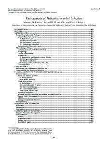
We can calculate this minimum analytically, using our dynamics equation and input constraints. We omit this equation for ud because it is long and not particularly revealing. In our control input, we wish to decrease the bias to zero as we move away from the reachable set. For some δ > 0, we choose † if Vˆ (xd (tk )) = 0 u (xd (tk ), dd (tk )) ud (tk ) = (δ − Vˆ (xd (tk )))u† (xd (tk ), dd (tk ))/δ if Vˆ (xd (tk )) ∈ (0, δ) (2.36) 0 if Vˆ (xd (tk )) ≥ δ. The theory behind the modified Hamilton-Jacobi-Isaacs equation allows us to verify the safety of a continuous-time controller. It assumes a continuoustime system as well as a continuous state space. In our implementation, we discretize the state space to estimate V . We also discretize time in Ptolemy II to simulate the system. In addition we suffer round-off error effects from using the computer. Under these conditions, we can no longer verify safety; we can only simulate the system to check for unsafe behaviors. The level set method of [13] provides high-resolution estimates of V , which helps ensure the safety guarantee is generally met. The forward Euler integration method of Ptolemy II suffers errors in estimating the dynamics. When the step size h is large, the integration suffers from truncation error; when h is small the integration suffers from roundoff error [7]. In our simulations we choose an ad-hoc value of h to be 0.33ms, corresponding to a 30Hz refresh rate of the images on the screen. In spite of these numerical limitations, through simulation, we have not been able to steer the aircraft through the no-fly zone. Figure 2.1 shows some actual trajectories observed when the user tried different strategies. Trajectories of the algorithm which uses knowledge of the pilot input are shown in Figure 2.1. This trajectory assumes knowledge of the pilot input, and the control is computed by Equation 2.36. 18
User Held Steady
User Turned away from No-Fly Zone
User Tried to Crash into No-Fly Zone
No-Fly Zone
Figure 2.1: A user tried the algorithm in Ptolemy II, and created these trajectories, which depended on his input. This behavior is consistent with that of Figure 1.1. This trajectory assumes knowledge of the pilot input, and the control is computed by Equation 2.36.
2.2.1
A Note on Our Dynamics Equation
Recall our simple model of the aircraft dynamics: xp1 (t) s cos xh (t) f xp2 (t) , u(t), d(t) = s sin xh (t) . xh (t) u(t) + d(t)
(2.37)
We mentioned in Chapter 1 that also limit the value of u(t) + d(t) to the range [−M, M ], but we do not include this in our dynamics model. We will now see why this is okay. From differential game theory, an optimal control input will maximize the Hamiltonian while the optimal disturbance will minimize the Hamiltonian 19
[11]. In our case an optimal control input is one which tries to move the state maximally away from the reachable set, while the optimal disturbance input tries to move it maximally into the reachable set. If we let � Vp1 (x(t)) Vp2 (x(t)) Vh (x(t)) = ∇V ∗ (x(t))T , (2.38) then the Hamiltonian is Vp1 (x(t))s cos xh (t) + Vp2 (t)s sin xh (t) + Vh (t)(u(t) + d(t)).
(2.39)
At each time t, the optimal control and disturbance inputs are then u∗ (x(t)) = 1.5M sgn Vh (t), d∗ (x(t)) = −M sgn Vh (t),
(2.40) (2.41)
and the optimal Hamiltonian is Vp1 (t)s cos xh (t) + Vp2 (t)s sin xh (t) + 0.5M |Vh (t)|.
(2.42)
In our computation of V ∗ , we must assume u∗ and d∗ are applied [13]. At each t then u(t) + d(t) = ±0.5M . Because |u(t) + d(t)| will always be less than M , we can use the dynamics in Equation 1.3 to calculate V ∗ without explicitly including the fact that we limit u(t) + d(t) to the range [−M, M ] for safety reasons.
20
Chapter 3 Other Soft Walls Control Approaches In this section we present some results on two other Soft Walls control strategies we have considered before using the method of Chapter 2.
3.1
Solution for Half-Space No-Fly Zone
This chapter describes a Soft Walls controller designed by Xiaojun Liu [4]. This controller worked well in simulations, and we prove its safety here. We will consider a particular no-fly zone in this chapter, a half-space in R2 . We let T = {x(t) ∈ X | xp1 (t) > 0}. See Figure 3.1. Here x(0) ∈ Init = {x ∈ X | xp1 (t) < −2s/M }. This choice of Init is important in verifying our controller. One parameter we use in this controller design is τ : X → R+ . τ (x(t)) is, the minimum time it takes for the pilot to hit the no-fly zone from state x(t), given zero control input. That is � (3.1) τ (x(t)) = min tˆ x(t + tˆ) ∈ ∂T , d∈D
where x(t + tˆ) =
Z
t+tˆ
f (x(s), 0, d(s))ds.
(3.2)
t
Finding τ (x(t)) is equivalent to minimizing the cost function Z t+tˆ h(x(t + tˆ)) + g(x(s), d(s))ds t
21
(3.3)
No-Fly Zone
Figure 3.1: The no-fly zone
where for all t ∈ I, h : X → R and g : X × D → R are h(x(t)) = 0 g(x(t), d(t)) = 1
(3.4) (3.5)
For notational convenience, let us assume xh (t) ∈ (−π, π]. We define d : X → D as the optimal disturbance at state x. That is, if d(t) = d∗ (x(t)), d will minimize τ (x(t)) at each t ∈ I. ∗
Lemma 3.1. For all t ∈ I, ( |xh (t)|−| sin xh (t)| xp1 (t) − �s M τ (x(t)) = |xh (t)| 1 − M arcsin | sin xh (t)| + M
−s| sin xh (t)| M −s| sin xh (t)| M
if xp1 (t) ≤ M xp1 (t) s
�
if xp1 >
(3.6) with
M ∗ d (x(t)) = 0 −M
if xh (t) < 0 if xh (t) = 0 if xh (t) > 0
(3.7)
Proof. Along the optimal trajectory, the optimal cost-to-go J ∗ : X × I → R will satisfy the Hamilton-Jacobi-Bellman equation [2]: g(x(t), d∗ (x(t))) + ∇t J ∗ (x(t), t)∇x(t) J ∗ (x(t), t)T f (x(t), 0, d∗ (x(t))) = 0, (3.8) ∗ J (x(t), t + τ (x(t))) = h(x). (3.9) 22
Here J ∗ (x(t), t) = τ (x(t)). We prove the lemma by proving that Equation 3.8 is satisfied for all t using d∗ (x(t)) and τ (x(t)). Case 1. (xh (t) = 0) Since | sin xh (t)| = 0, xp1 (t) ≤ −s| sin xh (t)|/M is trivially satisfied, and J ∗ (x(t), t) = −xp1 (t)/s. Here d∗ (x(t)) = 0. Since d∗ (x(t)) = 0, xh (t˜) = 0 will remain true for all times t˜ ≥ t. We see that ∇x(t) J ∗ (x(t), t) = (−1/s, 0, 0)T and ∇t J ∗ (x(t), t) = 0. Then g(x(t), d∗ (x(t))) + ∇t J ∗ (x(t), t)∇x(t) J ∗ (x(t), t)T f (x(t), 0, d∗ (x(t))) = −1 s cos xh (t) = 1 − cos 0 = 0. (3.10) 1+ s Case 2. ((xh (t) > 0)∧(xp1 (t) ≤ −s| sinMxh (t)| )) Here xh (t) will be decreasing to zero, since d∗ (x(t)) = −M . If xh (t + δt) becomes zero at some time t + δt, then d∗ (x(t)) = 0. When xh (t) > 0, | sin xh (t)| = sin xh (t), and J ∗ (x(t), t) = (xh (t) − sin xh (t))/M − xp1 (t)/s. We see that ∇x(t) J ∗ (x(t), t) = (−1/s, 0, (1 − cos xh (t))/M )T and ∇t J ∗ (x(t), t) = 0. Then g(x(t), d∗ (x(t)) + ∇t J ∗ (x(t), t)∇x J ∗ (x(t), t)T f (x(t), 0, d∗ (x(t))) = 1 − cos xh (t) 1 = 0. 1 − s cos xh (t) − M s M The time required for xh (t) to go to zero is δt = xh (t)/M . From our dynamics, Z
t+xh (t)/M
s cos xh (t˜)dt˜
xp1 (t + δt) = xp1 (t) + t
Z
t+xh (t)/M
s cos(xh (t) + M (t − t˜))dt˜
= xp1 (t) + t
s s = xp1 (t) − sin 0 + sin xh (t) M M s = xp1 (t) + sin xh (t) M
(3.11)
Since we require that xp1 (t) < −s sin xh (t)/M , xh (t) will reach zero before the target is reached. Then d∗ (x(t + δt)) = 0 and the time remaining before collision is now τ (x(t)) − xh (t)/M = − sin xh (t)/M − xp1 (t)/s = −xp1 (t + δt)/s. We have already verified the solution is optimal for any time t˜ when d∗ (x(t˜) = 0 in Case 1. 23
Case 3. ((xh (t) < 0)∧(xp1 (t) ≤ −s| sinMxh (t)| )) This proof is nearly identical to the proof of Case 2, so we omit it here. Case 4. ((xh (t) > 0) ∧ (xp1 (t) > −s| sinMxh (t)| )) Here xh (t) will be decreasing, but as we saw in Case 2, it will never reach zero, so the optimal ˜ disturbance d∗ (x(t˜) = −M will � remain constant for � all t until collision. Here M x (t) x (t) J ∗ (x(t), t) = hM − M1 arcsin sin xh (t) + sp1 . Again ∇t J ∗ (x(t), t) = 0 and h � �i−1 M xp1 −1 1 − sin x (t) + h s s ∗ . (3.12) 0 ∇x(t) J (x(t), t) = �i−1 h � 1/M 1 cos xh (t) 1 − sin xh (t) + M xsp1 (t) − M Then g(x(t), d∗ (x(t)) + ∇t J ∗ (x(t), t)∇x(t) J ∗ (x(t), t)T f (x(t), 0, d∗ (x(t))) = � � ��−1 M xp1 (t) 1 − cos xh (t) 1 − sin xh (t) + s � � ��−1 M xp1 (t) − 1 + cos xh (t) 1 − sin xh (t) + = 0. (3.13) s Case 5. ((xh (t) < 0)∧(xp1 (t) > −s| sinMxh (t)| )) This proof is nearly identical to the proof of Case 4, so we omit it here. Lemma 3.2. (τ (x(t)) is continuous with respect to t. Proof. We know x(t) is continuous with respect to t, because f (x, u, d) is continuous and u(t) and d(t) are bounded. It is easy to see that τ (x(t)) is continuous with respect to x(t) whenever xh (t) 6= 0 and xp1 (t) 6= −s| sin xh (t)|/M . If xh (t) = 0, xh (t) − sin xh (t) xp1 (t) xp1 (t) − = − M s s −xh (t) + sin xh (t) xp1 (t) = − . M s
24
(3.14)
and � � � � 1 M xp1 (t) 1 M xp1 (t) xh (t) − arcsin sin xh (t) + = arcsin = M M s M s � � −xh (t) 1 M xp1 (t) − arcsin − sin xh (t) + (3.15) M M s If xp1 (t) 6= −s| sin xh (t)|/M , � � |xh (t)| 1 M xp1 (t) |xh (t)| − arcsin | sin xh (t)| + = = M M s M |xh (t)| − | sin xh (t)| xp1 (t) − . (3.16) M s Because the composition of continuous functions is continuous functions is continuous [17], τ (x(t)) is continuous with respect to t. We can now use τ (x(t)) to synthesize a safe controller. Theorem 3.3. Let u† : X → U be f xh (t) if τ (x(t)) ≤ 1.5M sgn † 3M π u x(t)) = 2π−4 (τ (x(t)) − M ) sgn f xh (t) if τ (x(t)) ∈ 0 if τ (x(t)) >
2 M � 2 π , M M π . M
(3.17)
where sgn : R → R is ( sgn a sgn f x= 1
if a 6= 0 if a = 0.
(3.18)
If x(0) ∈ Init, then for all d ∈ D and all t ≥ 0, x(t) ∈ / T. Proof. Consider the states where τ (x(t)) = 2/M . From Equation 3.6, we see that if xp1 (t) ≤ −s| sin xh (t)|/M , then τ (x(t)) = 2/M if xp1 (t) =
s (|xh (t)| − | sin xh (t)| − 2). M
(3.19)
For these values of x(t), the condition that xp1 (t) ≤ −s| sin xh (t)|/M is equivalent to the condition that |xh (t)| ≤ 2. Clearly, for all |xh (t)| ≤ 2, xp1 (t) ≤ 0 if τ (x(t)) = 2/M . 25
If xp1 (t) > −s| sin xh (t)|/M , then τ (x(t)) = 2/M if xp1 (t) =
s [sin(|xh (t)| − 2) − | sin xh (t)|] M
(3.20)
For these values of x(t), the condition that xp1 (t) > −s| sin xh (t)|/M is equivalent to the condition that |xh (t)| > 2. Here xp1 (t) ≤ 0 only if |xh (t)| ≤ π/2 + 1, since for values greater than this, sin(|xh (t)| − 2) − | sin xh (t)| > 0. For our initial condition x(0) ∈ Init and from Equation 3.6, the minimum possible value of τ (x(0)) is 2/M , which occurs when xh (t) = 0 and xp1 (t) = −2s/M . Using Lemma 3.2, this means that if at any time t˜, x(t˜) ∈ T , τ (x(t)) = 2/M , for some t < t˜. If τ (x(t)) = 2/M , at time t, and xh (t) ≥ 0, then u† (x(t)) = 1.5M . This value will decrease only if τ (x(t˜)) > 2/M for some t˜ > t. Whenever the u† x(t)) = 1.5M and xh (t) ∈ [0, pi), the pilot inputR that t maximizes xp1 (t) is d(x(t)) = −M . To see this, we let, g(x(t), t) = scos( 0 [u† x(s))+ Rt d(x(s))]ds). Then xp1 (t) = 0 g(x(s), s)ds. The pilot input which maxiRt Rt mizes g(x(t), t) will minimize 0 [u† x(s)) + d(x(s))]ds, assuming 0 [u† x(s)) + d(x(s))]ds ∈ [0, pi). By the Hamilton-Jacobi-Bellman equation, d(x(t)) = −M , will minimize this function. For τ (x(t)) = 2/M and xh (t) ∈ [0, pi/2), xp1 (t) will increase until time t˜, R t˜ when t [u† x(s)) + d(x(s))] = π/2. If xh (t) ≥ π/2, xp1 (t) will be decreasing. If xh (t) ∈ [0, pi/2), given the pilot input d(x(t)) = −M which maximizes xp1 (t) in for times in the range [t, t˜], then t˜ = t + 2(π/2 − xh (t))/M . At that time � � Z t˜ M (τ − t) xp1 (t˜) = xp1 (t) + s cos xh (t) + 2 t � � 2s M (t˜ − t) = xp1 (t) + sin xh (t) + xp1 (t) + M 2 2s π = xp1 (t) + sin M 2 2s = xp1 (t) + (3.21) M Since xp1 (t) = Ms (x( t)h − sin xh (t) − 2) in this case, xp1 (t˜) = Ms (xh (t) − sin xh (t)) ≤ 0, since ∀x > 0, x > sin x. Whenever xh (t) = π, we can see that τ (x(t)) ≤ π/M from Equation 3.6, so the bias will eventually decrease as xh (t) increases by the continuity of 26
τ (x(t)). Therefore, if xh (t) ≥ 0, we know that the bias will prevent x from entering the target set. The proof is similar if xh (t) < 0, so we omit it here. We have proved u† is a safe controller. See [4] for results from this control strategy.
27
3.2
A Geometric Approach
This is a solution first proposed by Ashwin Ganesan. I present it here as a method we have considered but not implemented. This solution is based on the geometry of aircraft trajectories. I
���� �
���� �
Figure 3.2: The dot represents the aircraft, which is moving along the center trajectory. The circle trajectories represent turns at rmin , which in this case equals 2s/M .
If the aircraft banks left or right with with rate of change in heading ±M/2, it will follow one of the trajectories in figure 3.2. Now suppose we wish to prevent the aircraft from entering the no-fly zone. As the aircraft approaches the no-fly zone boundary, one of the minimum-turning-radius trajectories from figure 3.2 will intersect the no-fly zone boundary ∂(T ). As long as the other trajectory has not yet intersected the boundary, the aircraft can still avoid entering the interior of the no-fly zone by moving along this trajectory. At the instant the second trajectory intersects the boundary, we can force the aircraft to fly along the second trajectory by applying u(t) = ±1.5M . Then even if the pilot applies d(t) = ∓M , the aircraft will turn away from the no-fly. This situation is depicted in figure 3.3. We can change the bias to zero at the point when (and if) the other trajectory no longer intersects the no-fly zone or its boundary. We would like the control bias u to increase and decrease from zero gradually, so as not to shock the pilot. If we use this method there will be discontinuities in u. We abandoned this strategy when we could not develop a good way to increase and decrease the bias gradually and still guarantee safety.
28
Figure 3.3: On the left picture, the aircraft can still avoid the no-fly zone by banking right. On the right picture, the aircraft must be forced to bank right at a rate greater than or equal to −M/2.
29
Chapter 4 Conclusions and Future Work Soft Walls is a new approach to aviation security. From a technical standpoint, Soft Walls is a control system strategy. Under this framework, it is a collision avoidance problem. When our dynamics equation is Lipschitz continuous, we can guarantee collision avoidance by describing the unsafe set of states through a cost function. We can then model our problem as a game between controllable and uncontrollable inputs. With this formulation we estimate a verifiably safe controller using the Hamilton-Jacobi-Isaacs equation. Simulation validates this strategy. One drawback of this strategy is that solving the game requires us to solve a problem over the entire state space. The computation and storage required to solve this problem grows exponentially with the number of states [13]. The approach of Section 3.1 uses a particular dynamics equation for the aircraft and a particular no-fly zone geometry. In this case, we were able to derive a safe controller which guarantees the aircraft will always avoid the no-fly zone. This controller is based on the minimum time required for the aircraft to reach the no-fly zone. The advantage of this approach is that it requires only a small amount of online computation. This approach has two disadvantages. The first is that it depends heavily on the dynamics equation we choose. Changing the dynamics would require resolving the minimum-time-to-reach function and the control input function. This may be difficult or impossible to do. Changing the shape of the no-fly zone would have the same consequence. The approach of Section 3.2 uses a particular dynamics equation, but it 30
puts only very limited restrictions on the shape of the no-fly zone. It works by analyzing the trajectories of the aircraft if it is forces to turn right or left, and then forces a turn when necessary. While this approach removes the restrictions on the no-fly zone, it still was solved for a particular dynamics. It also uses no blending to gradually increase the bias from zero. It is unclear how to do this or how to extend this method under different dynamics. For these reasons, the game formulation of Chapter 2 is the most promising of these control strategies, because it does not depend on the system dynamics or the no-fly zone shape. Research on appropriate discretizations, of both time and space may reduce the computational complexity of this approach. The research question here is how can you discretize the problem to get useful results? Since the system will be implemented in discrete-time, the formulation should be extended to discrete-time. Another research topic is that of robustness. In particular, how can you make the system safe with respect to real-life factors such as uncertainty in state information and the timing jitter in a discrete-time realization of the system? This is ongoing research, and we will address these questions. The answers, we hope, will have applications far beyond Soft Walls.
31
Bibliography [1] Martino Bardi. Some applications of viscosity solutions to optimal control and differential games. In I. Capuzzo Dolcetta and P. L. Lions, editors, Viscosity Solutions and Applications. Springer, 1995. [2] Dimitri P. Bertsekas. Dynamic Programming and Optimal Control, volume 1, chapter 3. Athena Scientific, 2nd edition, 2000. [3] Shuvra S. Bhattacharyya, Elaine Cheong, John Davis II, Mudit Goel, Christopher Hylands, Bart Kienhuis, Edward A. Lee, Jie Liu, Xiaojun Liu, Lukito Muliadi, Steve Neuendorffer, John Reekie, Neil Smyth, Jeff Tsay, Brian Vogel, Winthrop Williams, Yuhong Xiong, and Haiyang Zheng. Ptolemy II: Heterogeneous concurrent modeling and design in Java. Technical report, University of California, Berkeley. [4] J. Adam Cataldo, Edward A. Lee, and Xiaojun Liu. Preliminary version of a two-dimensional technical specification for softwalls. Technical Memorandum UCB/ERL M02/9, University of California, Berkeley, April 2002. [5] L. C. Evans and P. E. Souganidis. Differential games and representation formulas for solutions of hamilton-jacobi-isaacs equations. Indiana University Mathematics Journal, 33(5):773–797, 1984. [6] Lawernce C. Evans. Partial Differential Equations, chapter 10. American Mathematical Society, 1998. [7] C. William Gear. Numerical Initial Value Problems in Ordinary Differential Equations. Series in Automatic Computation. Prentice-Hall Inc., 1971.
32
[8] Rufus Isaacs. Differential Games: A Mathematical Theory With Applications to Warfare and Pursuit, Control and Optimization. Krieger Publication Company, 2 edition, 1975. [9] Edward A. Lee. Soft Walls–modifying flight systems to limit the flight space of commercial aircraft. Technical Memorandum UCB/ERL M01/31, UC Berkeley, September 2001. [10] Edward A. Lee. Soft Walls–frequently asked questions. Technical Memorandum UCB/ERL M03/31, UC Berkeley, July 2003. [11] Joseph Lewin. Differential Games: Theory and Methods for Solving Game Problems with Singular Surfaces. Springer-Verlag, 1994. [12] Jerry B. Marion and Stephen T. Thornton. Classical Dynamics of Particles and Systems, chapter 7. Harcourt College Publishers, 4 edition, 1995. [13] Ian Mitchell. Application of Level Set Methods to Control and Reachability Problems in Continuous and Hybrid Systems. PhD thesis, Stanford University, 2002. [14] Stanley Osher and Ronald Fedkiw. Level Set Methods and Dynamic Implicit Surfaces. Springer, 2002. [15] Claire Tomlin, John Lygeros, and Shankar Sastry. A game theoretic approach to controller design for hybrid systems. In Proceedings of the IEEE, volume 88, July 2000. [16] Claire Tomlin, George Pappas, and Shankar Sastry. Conflict resolution in air traffic management: A study in multi-agent hybrid systems. IEEE Transactions on Automatic Control, 43(4):509–521, April 1998. [17] Neil A. Watson. Mathematical Analysis Explained, chapter 3. World Scientific, 1993.
33