Available online at www.sciencedirect.com
Procedia Engineering 49 (2012) 228 – 238
Evolving Energy-IEF International Energy Congress (IEF-IEC2012)
Control and management of particulate emissions using improved reverse pulse-jet cleaning systems Nicholas Findanisa* and Matthew Southama a
Tyco Environmental Systems, 268 Milperra Road, Milperra 2214, Australia Elsevier use only: Revised 29th June 2012; accepted 10th July 2012
Abstract The control of particulate emissions from various applications such as power generation, cement plants, minerals processing etc. is essential to meet government regulatory standards. Filter bags and cartridge elements are typical common mediums used to separate particulates. A common method used to clean filters in the extraction of particulate matter from a fluid stream, is Reverse Pulse-Jet (RPJ) cleaning systems. The operation of the RPJ cleaning system relies on stored energy in the form of compressed gas, which is usually air. In this paper, the design and application of an efficient cleaning system to minimise the use of compressed gas to achieve the required filter cleaning is described. In an RPJ cleaning system, a high-energy pulse of compressed gas is delivered into the filter medium to rapidly increase the internal pressure and, in the case of filter bags, accelerate the filter material to force the break-up of dust cakes that form on the filter surface. One key component of the cleaning system is an extremely fast acting valve that controls the flow of the high pressure gas, the other is the blowtube. The blowtube is a commercial steel pipe with a number of outlet orifices distributed along the longitudinal axis and centrally located above each filter. The cleaning system improvements have been achieved by advances in valve and blowtube design that have enabled increases in the peak pressures developed in the filters whilst minimising the response rate of the system to decrease the air consumption. The store of potential energy must be effectively and efficiently converted into kinetic energy to utilise the available energy to build pressure in the filter. Thus, by improving the RPJ cleaning system the operating costs associated with the compressors are reduced thereby decreasing the environmental impact of operating filter cleaning systems, to more efficiently remove particulate matter from fluid streams.
© 2012 The Authors. Published by Elsevier Ltd. Selection and/or peer-review under responsibility of the International © 2012 The Authors. Published by Elsevier Ltd. Selection and/or peer-review under responsibility of the International Energy Foundation Energy Foundation Keywords: Emission; particulate; reverse pulse jet; cleaning system
Nomenclature A/C EOT MOT RPJ
Air to Cloth ratio (m/s) Electrical On Time Mechanical On Time Reverse pulse-jet
* Corresponding author. Tel.: +612-9792-0235; fax: +612-9773-0674. E-mail address:
[email protected].
1877-7058 © 2012 The Authors. Published by Elsevier Ltd. Selection and/or peer-review under responsibility of the International Energy Foundation doi:10.1016/j.proeng.2012.10.132
Nicholas Findanis and Matthew Southam / Procedia Engineering 49 (2012) 228 – 238
1. Introduction The control and management of emissions from industrial processes is a key focus for governments around the globe, One such area is air pollution control of particulate emissions from a variety of sources [1]. Particulate emission control is the removal of particles carried in effluent gases originating from power generation, industrial processes and commercial plants. The particles or dispersoids can be characterized by their physical, chemical and electrical properties, their particle size and structure, rate of settling under gravity, optical activity, ability to absorb an electrical charge, the surface-to-air volume ratio, and the chemical reaction rate [1]. When the particle is greater than 100 m in diameter they settle rapidly and are prevented from being dispersed or suspended for significant amount of time. This size of particulate matter is not generally considered. The dispersoids are classified as dust, smoke, fumes and mists. For particles sizes larger than 10 m, gravity and centrifugal force methods are used for removal from the gas stream. Where the particle size is approximately 1 m and smaller effective methods are based on electrical force, impaction, interception or inertial diffusion. In this case there are different technologies commercially available to remove or filter this particulate matter from an airstream, which normally passes through a type of dust collector or baghouse. Some devices are ElectroStatic Precipitators (ESP), Fabric Filters (FF) and high-energy wet scrubbing. Filtration of the particulate matter is only but the first step in the emissions control and management process. The particulate matter also needs to be removed from the filter medium, collected in some sort of hopper, transferred to a waste vehicle and transported away for either waste storage or be used in an innovative waste management process [1]. For example, some technologies use waste materials to become a constituent in new material or become the bulk substrate of the material itself. The efficiency of the dust collector to remove the particulate matter from the process may not only affect the control and management of the emission of particulate matter but of other emissions in the industrial process. For example, in power generation there are three significant classes of emissions from fuel-burning processes: the particulate matter, sulphur oxides and nitrogen oxides. A reduction in the efficiency of the fuel-burning or combustion process, could lead to an increase in the production of particulate matter and/or harmful oxides. Therefore, if the dust collector is not adequately designed the processes upstream could be adversely affected leading to incomplete combustion, temperature gradients, pressure gradients that increase the production of pollutants. Fabric filter dust collectors are generally preferred over other types of particulate filtration [2] since they can provide greater control of outlet emissions independent of the inlet dust loading, the innovation of special fabrics and fabric finishes can reduce emissions below the capabilities of other types of collectors, chemical reactions of the dust cake on the fabric can improve the removal of sulfur dioxide in dry flue-gas desulphurization systems by 15 20 percent and easy material handling of the dry collected particulate matter. In the design of fabric filter dust collectors, consideration is given to cleaning mechanism and the type of fabric-filter to be used. A critical feature of the successful operation of dust collectors is the cleaning system [2]. The cleaning system ensures that the dust collector continues to operate effectively within its design limits providing the regulatory or better removal of particulate matter before the gas stream is passed back into the process or released to the atmosphere. Failure to provide a suitable cleaning system design, would force a plant outage which normally is very costly. Further, it could require that the dust collector and cleaning system be replaced or re-designed. Plant outage in this case would be extended until the redesign, manufacture of parts and installation is completed resulting in substantial and even crippling financial losses to the responsible party. An effective method used to clean fabric filters and other types of filters such as ceramic candle filters is Reverse PulseJet (RPJ) cleaning systems [2].
1.1. Reverse Pulse-Jet (RPJ) Cleaning System A fabric filter dust collector functions, by trapping the particulate matter in the gas stream as it passes through the porous filter material. The filter material is designed with different air permeability, tensile strength, abrasion resistance, chemical resistance, operating temperatures and textures and finishes among other properties. The variation in filter material exists for the purpose of providing a suitable material for the filtration of a variety of particulate matter in different environments. The air permeability is a measure of the amount of air that is able to pass through a given filter area. This is measured as ratio the of volumetric flow rate of air per square meter of filter material. Thus, the units of air permeability are in m/s, indicating a velocity measure as would be expected since it is a ratio of the volumetric flow rate and area. The specified air permeability
229
230
Nicholas Findanis and Matthew Southam / Procedia Engineering 49 (2012) 228 – 238
by the manufacturer for the filter material is in the clean state yet to be installed. In the design of the RPJ cleaning system, it is required to know the air permeability or more commonly defined as the Air to Cloth ratio (A/C ratio) when the filter is dust-laden at the point where it requires cleaning. Additionally, the pressure drop across the filter bag in the dust-laden state is required [3]. The flow of gas through the filter from the dirty side (air with particulate matter before filtering) to the clean side (filtered air) is called the forward flow through the dust collector or through the filter bag. The flow through the dust collector is usually forced or drawn using a large fan commonly called the I.D. fan or induced draft fan. The conditions of forward flow are made up of the volumetric flow rate and pressure drop of the dust-laden filter bag [3]. In the process of reverse pulse-jet filter cleaning we have the reverse flow conditions. This is the flow of gas issued by the cleaning system, through the filter from the clean side of the filter to the dirty side of the filter. For this process to occur the reverse pulse-jet flow into the filter bag must be able to firstly overcome the forward flow coming up through the filter bag and then be able to provide cleaning flow through the filter bag to remove the build-up of dust cakes on the dirty side of the filter material. For example, if we have a filter bag that is 150 mm in diameter and 8 m long this has an area of 3.77 m2. The A/C ratio for a typical coal-fired boiler is approximately 0.025 m/s. The volumetric flow rate through the dust collector with 3000 filter bags is 287.27 m3/s or approximately 96 L/s through each filter bag. A typical pressure drop across the dust laden filter bags is 1500 Pa. The forward flow conditions are defined as 96 L/s at 1500 Pa. Therefore, the pulse-jet flow into the filter bag has to be greater than 96 L/s and create a pressure inside the filter bag that is higher than 1500 Pa. A typical RPJ cleaning system consists of three main components: compressed air supply, valve and blowtube. The valve is also more explicitly known as pulse-jet valve. The blowtube is the name given to the pipe connected to the valve and configured with the same number of outlets as the number of filters to which it delivers the reverse flow. In the present work, improvements are made to the two critical components for the operation of a well-designed cleaning system; the pulse-jet valve and the blowtube. The RPJ cleaning system is energised from a store of compressed gas. The work a compressor must do to compress the gas comes at a cost. For a large dust collector comprised of over a thousand pulse-jet valves, pulsing a number of valves simultaneously every few seconds with each valve possibly using 300 L of air per pulse is a large operating cost. Thus, there is a need to increase the efficiency of the cleaning system so as to decrease the overall air consumption. The lower power consumption of the compressor goes towards decreasing the carbon footprint of the dust collector and the overall process whether that be power generation, cement plant, minerals processing etc. Operators of industrial plants are keenly interested in making improvements wherever they can be obtained provided it can be shown that there is a net operating cost benefit. Government regulatory agencies, such as the Environmental Protection Agency (EPA) in the United States and Australia with its own Environmental Protection Authority (EPA), are tightening the standards on pollutants released into our environment. The flow physics of an RPJ cleaning system falls into the category of gas dynamics. The stored energy in terms of the compressed gas and the quick release of the high potential energy from the gas results in a compressible flow. The high speed phenomena associated with the system need to be further investigated to gauge whether there exist possibilities to enhance any inherent flow characteristics to improve the cleaning system. This deficiency in understanding of the system gives the impetus needed to further investigate and gauge whether there exist possibilities to enhance any inherent flow characteristics to improve the cleaning system. In the present work, a comparison is made between two Goyen diaphragm rmance of the cleaning system will be compared between the older Series 2 valve and the current development with the Series 4 Shockwave diaphragm valve. Further, the present work investigates the effects of altering some fundamental parameters in the configuration of a typical RPJ cleaning system. An important parameter in the effective operation of the diaphragm valve is the length of the pilot line. This is the line that connects the main valve to the remotely placed pilot valve. Pulse jet valves may also incorporate an integral pilot in some cases. The maximum line length for the effective operation of each diaphragm valves will be determined and compared. A poorly performing cleaning system could be due to a valve not being fully opened due to a pilot line being excessively long making the pilot valve incapable of exhausting the air volume within the added pilot line length. Additionally, the solenoid Electrical-On-Time (EOT) is examined in relation to pilot line length. Other technologies could be added to the system to extract fluid dynamic losses and improve the flow through the system. Advancements made by the authors in subsonic flows [4, 5, 6, 7] could have an application to modify the gas dynamics of an RPJ cleaning system which could provide not only improvements to flow but further insight to the physics of high speed flows.
Nicholas Findanis and Matthew Southam / Procedia Engineering 49 (2012) 228 – 238
2. Procedure and Method 2.1. Laboratory testing and blowtube design The physical testing was carried out in our custom designed Clean Air Systems (CAS) testing facility, located at the Milperra headquarters in Australia. The test rig caters for different valve configurations to be mounted and tested within a pressure range of 0 10 bar.g. It has twin variable headers to adjust for changes in the required volume from 0 708 L. The pilot valve actuation can be controlled with either DC or AC voltage. A high-speed data acquisition (DAQ) system which has been custom designed to acquire multiple pressure traces and flow rates at different points on the system will be used throughout the testing. The DAQ system is controlled by the Labview software and uses a National Instruments analog to digital DAQ card. Error! Reference source not found. shows a schematic layout of the CAS test rig with the Goyen cleaning system configuration for the testing conducted. 2.2. Valve innovation and cartridge filter testing eries 2 diaphragm pulse valve and the Goyen RCAC25DD4 is the new Series 4 pulse valve featuring the proprietary Shockwave diaphragm with integrated spring. This series of valves has been developed as high performing valves. For each given valve size in the Series 4 the flow delivery is greater than previously released valve products of the same size in the Goyen pulse-jet diaphragm valve range. Each valve has the This consists of a Dresser nut coupling on the inlet and outlet of the valve. The actual physical setup has been tested in the CAS lab according to typical cartridge filter arrangements. The design has two headers. However, these two headers are inone side with straight with four outlets with The system configuration was tested with only one outlet exhausted. The rema and hose fitted over the plain tube outlet. Where the system consisted of two headers, these headers where connected with a then also under the system configuration which has two headers. This ensures that if for some particular reason if a header is isolated, then the cleaning system can operate safely with on a single header. The three system configurations were tested with different inlet feeds since this is a parameter that has been known to cause improper valve operation or each system. Additional selected system testing was performed It should be noted that matching the inlet pipe size to the nominal valve is the accepted practice and strongly recommended. In summary, the various sizes tested for the inlet feeds are as follows:
A typical normal operation of the cleaning system is operated at two different system pressures of: 80 psi.g 100 psi.g The Electrical-On-Time (EOT) of the valve operation is 100 ms. Another critical factor for resonance is the length of pilot line from the main valve to the pilot valve. The length of this line varies according to the distance of the pilot valve to the main valve. The pilot valves are all located in the pilot valve enclosure. The enclosure has different locations according to the system configuration. This translates to a range of different - 12 ft long. For the testing there were also two 90o bends that were installed. These bends were installed in the pilot line to determine whether any losses occurring due to flow through the bends could affect the valve operation.
231
232
Nicholas Findanis and Matthew Southam / Procedia Engineering 49 (2012) 228 – 238
Shown below in Table 1 are the different pilot line lengths used for the testing of each system configuration. While Goyen recommend for the pilot line length to ideally be less than 1.5m, this is often not observed in practice.
Table 1. Pilot line lengths
Pilot Line Length (ft)
Pilot Line Length (mm)
2.5
762
4
1219
5
1524
6
1829
7
2134
8
2438
9
2743
10
3048
12
3658
Pressure measurements were taken in the header manifold and in the blowtube. The blowtube was tapped and fitted with an adapter to connect pressure tubing leading back to the pressure transducer. The in-filter developed pressure is measured with a low pressure transducer that is connected to the fixed and sealed pressure tube that passes through the cartridge filter wall and sits flush with the inside face. The pressure transducer measures the differential pressure between the inside of the cartridge filter and the outside ambient air.
Nicholas Findanis and Matthew Southam / Procedia Engineering 49 (2012) 228 – 238
Fig. 1. Schematic layout of the CAS test rig.
233
234
Nicholas Findanis and Matthew Southam / Procedia Engineering 49 (2012) 228 – 238
3. Results and Discussion 3.1 Valve Innovation The performance of two valves was compared with each other. Results were taken of the system performance of each pulse-jet valve, the RCA25DD2 Table 2, additionally the variance of the cartridge pressures are shown in Figure 2 and Figure 3 for 80 psi.g and 100 psi.g header pressures respectively.
Table 2. Cartridge filter developed pressure
Cartridge Filter System 80 psi.g Pilot line length
RCA25DD2
100 psi.g
RCAC25DD4
RCA25DD2
RCAC25DD4
(ft)
(Pa)
(Pa)
(Pa)
(Pa)
2.5
1258
1430
1612
1973
4
1197
1573
1700
2051
6
1140
1558
1494*
2075
8
1231
*
1496
1474
*
1793
10
1132*
1691
1479*
1969
12
0
1304
0
1157
*
Note: The values marked indicate that the EOT needed to be increased for the valve to open fully.
Cartridge Press. (Pa)
2000
1500
1000
RCA25DD2 RCAC25DD4
500
0 0
5
10
Pilot line length (ft) Figure 2. Cartridge pressure at 80 psi system pressure for each valve.
15
Nicholas Findanis and Matthew Southam / Procedia Engineering 49 (2012) 228 – 238
2500
Cartridge Press. (Pa)
2000 1500 RCA25DD2
1000
RCAC25DD4 500 0 0
5
10
15
Pilot line length (ft) Figure 3. Cartridge pressure at 80 psi system pressure for each valve.
These results indicate the superior performance of the new RCAC25DD4 valve over the previous model. The developed pressure in the cartridge is on average 30% higher at 80 psi.g header pressure and 27% higher at 100 psi.g. Further, and more importantly, the for proper opening of the valve. The EOT needs ev thout struggling. However, there is a drop in the performance at this length as indicated in Figure 2 and Figure 3. In Figure 2 and Figure 3 the cartridge pressure is seen to decrease to zero with the use of the RCA25DD2 pulse-jet valve. The is due to the valve not operating at the longer pilot line lengths, resulting in no air flow into the filter and therefore no build-up of developed pressure. The performance of the valve-blowtube system at 80psi.g and 100 psi.g is shown in Figure 4 and Figure 5 respectively, than the RCA25DD2 which has a much smaller Mechanical-On-Time MOT and slightly lower peak pressure. The difference in performance between the two valves is more apparent at the lower system of 80 psi.g. At the same EOT, the RCA25DD2 flows about 1/3 of the volume of the RCAC25DD4. The response of the RCAC25DD4 is significantly faster to open with a slightly stepper curve in the opening rate of the diaphragm valve.
235
236
Nicholas Findanis and Matthew Southam / Procedia Engineering 49 (2012) 228 – 238
700 600
Pressure (kPa)
500 400 RCA25DD2 (Blowtube Press.) 300
RCA25DD2 (Hdr Press.) RCAC25DD4 (Blowtube Press.)
200
RCAC25DD4 (Hdr Press.)
100 0 0
100
200
300
400
500
600
EOT (ms) Figure 4. Cartridge filter. 80 psi.g header pressure. Blowtube and header pressures.
800 700
Pressure (kPa)
600 500 RCA25DD2 (Blowtube Press.)
400
RCA25DD2 (Hdr Press.)
300
RCAC25DD4 (Blowtube Press.)
200
RCAC25DD4 (Hdr Press.) 100 0 0
100
200
300
400
500
600
EOT (ms) Figure 5. Cartridge filter. 100 psi.g header pressure. Blowtube and header pressures.
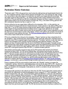
Shown in Figure 6 and Figure 7 is the developed pressure in the cartridge. It is evident from the two figures that the RCAC25DD4 is able to sustain the peak pressure in the cartridge for longer and produce a higher peak pressure as was reflected in Table 2. This is especially the case at the lower system pressure of 80 psi.g.
Nicholas Findanis and Matthew Southam / Procedia Engineering 49 (2012) 228 – 238
8
Pressure (W.G. in)
6
RCA25DD2 (Developed Press.) RCAC25DD4 (Developed Press.)
4 2 0 0
100
200
300
400
500
600
-2 -4
EOT (ms)
Figure 6. Cartridge filter. 80 psi.g header pressure. Cartridge developed pressure.
10
Pressure (w.G. in)
8 6 RCA25DD2 (Developed Press.)
4 2 0 0
100
200
300
400
500
600
-2 -4
EOT (ms)
Figure 7. Cartridge filter. 100 psi.g header pressure. Cartridge developed pressure.
improper valve operation in the system. Figure 4 and Figure 5 are typical of a system that is performing normally with good response rates in the opening and the closing of the valve as well as flow throughput. 4. Conclusions A well-designed RPJ cleaning system is able to balance two key elements, cleaning power and air consumption, the goal being to implement a low cost, efficient cleaning system. As such, pulsing the filter bags with an inadequate amount of cleaning power will result in excessive cleaning cycles in an attempt to lower the pressure drop in the dust collector although it will probably not be able to alleviate the dust-laden filter bags. Below a certain level, the cleaning cycle will not adequately remove the dust cake at all, leading to blocked or blinded filter elements, requiring a costly change out. On the other hand, an excessive amount of cleaning power does not provide any added advantages in terms of cleaning performance. This result is excessive wear on filter bags with possible premature bag failure, dust bleed through and
237
238
Nicholas Findanis and Matthew Southam / Procedia Engineering 49 (2012) 228 – 238
excessive air consumption requiring oversized air compressors. It is important to design an RPJ cleaning system that provides a suitable amount of cleaning power for the dust collector. The RCAC25DD4 was able to operate with a higher peak pressure and flow capacity than the RCA25DD2. This was evidenced in all cases; however it was made clear just how much cleaning improvement the RCAC25DD4 can provide over the RCA25DD2 when the system is large, despite being the of the same nominal valve size. Especially is this true, in the case of the pilot line length exceeds 6 ft and operates at the higher header pressure of 100 psi.g, however Goyen do not recommend pilot lines this long be used. The RCAC25DD4 can operate in this prescribed range without any increase in EOT nor a large drop in the cartridge filter developed pressure. Moreover, the RCAC25DD4 provided an increase in the flow capacity that would be desirable for this application. The testing has shown that through the innovative advancement of valve technology, such as the Goyen RCAC25DD4 and the design of an appropriate blowtube, substantial improvements can be gained in peak cleaning pressures through the filters. Further, the improved response of the valve will decrease the overall air consumption and energy usage.
Acknowledgements The authors would like to thank Tyco Environmental Systems for the facilities to perform the required experimental work and for the assistance of our colleagues. References [1] Singer JG. Combustion fossil power. 4th ed. Connecticut: Combustion Engineering Inc. 1991. [2] Simon X, Chazelet S, Thomas D, Bemer D, Regnier R. Experimental study of pulse-jet cleaning of bag filters supported by rigid rings. Powder Technology 2007; 172: 67-81. [3] RPJ Cleaning system design. Tyco Environmental systems, 1999. [4] Findanis N, Ahmed NA. The interaction of an asymmetrical localised synthetic jet on a side supported sphere. Journal of Fluids and Structures 2008; 24: 1006-1020. [5] Findanis N, Ahmed NA. Three-dimensional flow reversal and wake characterisation of a sphere modified with active flow control using synthetic jet. Advances and Applications in Fluid Mechanics 2011; 9 (1): 17-76. [6] Ahmed NA, Wagner DJ. Vortex shedding and transition frequencies associated with flow around a circular cylinder. AIAA Journal 2003; 41 (3): 542-544. [7] Yen J, Ahmed NA. Parametric study of dynamic stall flow field with synthetic jet actuation. Journal of Fluids Engineering, Transactions of the ASME 2012; 134 ( 7): Article number 071106.