Department of Electrical and Computer Engineering. University of ... The synchronous reluctance motor (SynRM) does not ... air-gap flux density distribution.
CONTROL AND PERFORMANCE OF A NINE PHASE SYNCHRONOUS RELUCTANCE DRIVE C.E. Coates*, D. Platt** and V.J. Gosbell** * Department of Electrical and Computer Engineering University of Newcastle ** Department of Electrical, Computer and Telecommunications Engineering University of Wollongong Abstract This paper deals with the control aspects of a nine-phase synchronous reluctance motor. Increasing the number of phases above three allows the stator MMF’s to be shaped so that the motor produces significantly greater torque / RMS ampere. Generalized d-q voltage and torque equations are given for the motor. Two methods of field-oriented control are considered. The first is based on a simple hysteresis strategy in the stator current plane. The second attempts to find the optimal inverter-switching configuration in the transformed d-q harmonic current planes. Simulation results for both controllers are presented. A 5kW experimental drive based on the hysteresis controller is described and its performance characteristics detailed. 1.
INTRODUCTION
The synchronous reluctance motor (SynRM) does not naturally produce sinusoidal flux waves in its air-gap. The rotor saliency of the SynRM produces a “square” air-gap flux density distribution. If a square current distribution interacts with this flux the SynRM generates its maximum torque per ampere. The square current machine also exhibits lower copper losses in comparison to a similarly rated sinusoidal current machine. These ideas are supported by recent work showing that the addition of a third harmonic space component to the MMF distribution effectively raises the torque per rms ampere of the motor [4, 7]. A design model has been proposed which assumes the SynRM is excited by an ideal square stator current distribution [2]. In the design model, direct axis excitation exists as a rectangular block of current over the rotor pole edges. Quadrature axis excitation exists as another rectangular block of current over the rotor pole face. Machines designed by this method require non-sinusoidal windings of more than three phases to approximate the ideal current distribution of the design model. An experimental nine-phase, four-pole 5kW motor has been designed and built based on the design model. This paper describes the development and implementation of a suitable speed controller for this motor. 2.
GENERALIZED EQUATIONS
To model and control the experimental motor’s performance requires the determination of appropriate voltage and torque equations. The key to obtaining these expressions is the formation of a stator
inductance matrix. Traditionally, approximations are made to the stator winding distribution and air-gap length as functions of angular displacement around the stator. These expressions are then used to determine the inductance values including the necessary harmonic components [6,8]. An alternative approach is to approximate the air-gap flux density distribution and hence determine flux linkages [3]. This method significantly simplifies the necessary calculations. It can be used to show the mutual inductance between two fully pitched, concentrated stator coils (separated by β radians) as a function of rotor position, α, is, M ab (α ) =
∞ 4 cos(n( 2α + β )) ( Ld − Lq ) ∑ 2 π n2 n =1( odd )
+
∞ 4 cos(nβ ) + ( ) L L ∑ d q 2 π n2 n =1( odd )
(1)
Ld and Lq are the inductances seen when the axis of a stator phase winding is aligned with the rotor direct and quadrature axes respectively. The stator inductance matrix, L(α), can be formed given the specific dimensions of the nine-phase machine. The matrix is symmetrical and a transformation matrix, T(α), can be found such that the orthogonal transformation, T(α)L(α)TT(α), yields a diagonal matrix whose diagonal elements are, Ld 1 =
36 Ld π2
Lq1 =
36 Lq π2
4 Ld π2
Lq 3 =
Ld 5 =
36 Ld 25π 2
Lq 5 =
36 Lq 25π 2
Ld 7 =
36 Ld 49π 2
Lq 7 =
36 Lq 49π 2
Ld 3 =
3.
4 Lq π2
These elements correspond to the fundamental, third, fifth and seventh harmonic, direct and quadrature components of stator inductance. The transformation matrix can also be applied to the stator voltage equation to determine the d-q voltage equations in harmonic component form. These equations are; did 1 + 2 Lq1ωiq1 dt diq1 − 2 Ld 1ωid 1 vq1 = rs iq1 + Lq1 dt di vd 3 = rs id 3 + Ld 3 d 3 + 6 Lq 3ωiq 3 dt diq 3 − 6 Ld 3ωid 3 vq 3 = rs iq 3 + Lq 3 dt di vd 5 = rs id 5 + Ld 5 d 5 + 10 Lq 5ωiq 5 dt diq 5 − 10 Ld 5ωid 5 vq 5 = rs iq 5 + Lq 5 dt di vd 7 = rs id 7 + Ld 7 d 7 + 14 Lq 7ωiq 7 dt diq 7 − 14 Ld 7ωid 7 vq 7 = rs iq 7 + Lq 7 dt vd 1 = rs id 1 + Ld 1
Field-oriented control involves separately controlling the direct and quadrature axis excitations in the motor. Different strategies can be used to achieve such goals as maximum torque, maximum rate of change of torque and maximum power factor [1]. Here a “constant current in the inductive axis” type controller is implemented. Figure 1 shows a simplified block diagram of this controller. Direct axis excitation is held at a constant value to maintain machine flux. Quadrature axis excitation is varied to control the motor torque. The control methods presented here are essentially means to implement the current controller block in Figure 1. They take the direct and quadrature axis excitation values and determine the appropriate inverter switching configuration in any given control cycle. State variables
(2) Constant
(3) (4) (5) (6) (7) (8) (9)
The corresponding d-q torque expression can be determined by considering the change in system coenergy with respect to rotor position. The torque equation is, Te = 2( Ld 1 − Lq1 )id 1iq1 + 6( Ld 3 − Lq 3 )id 3iq 3 (10)
id,ref Current Controller
ωref
Note that the stator winding of the experimental SynRM is star connected with no neutral. As such there are only eight independent stator phase currents and no zero sequence component. Only eight transformed variables are required to describe the system.
+ 10( Ld 5 − Lq 5 )id 5iq 5 + 14( Ld 7 − Lq 7 )id 7 iq 7
CONTROL STRATEGY
PI Speed Controller
iq,ref
S
Inverter/ SynRM
ωf/b
Figure 1 Simplified block diagram of SynRM speed controller Two strategies are considered. The first is based on a simple hysteresis strategy in the stator current plane. The second attempts to find the optimal inverterswitching configuration in the transformed d-q harmonic planes. 3.1
Stator Current Controller
The stator current controller “splits” the stator winding into two sections similar to the original design model. Phase windings located over the rotor pole edges carry direct axis current. The windings located over the rotor pole face carry quadrature axis current. By knowing the rotor position and its dimensions the appropriate phase current references can be generated. A similar strategy has been used in a field regulated reluctance machine [5]. However, in this instance the individual phase windings were isolated and each supplied by a separate full bridge inverter. Here the windings will be star connected and supplied from a nine-phase voltage source inverter eliminating half of the power switches required in the comparable field regulated machine. Generating the stator current reference is complicated by two practical constraints. First, stator current is not
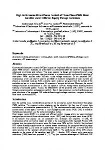
continuously distributed but is concentrated in the stator slots. Step changes in the stator current can only be made at a slot opening. As the rotor moves individual phase windings at either edge of the rotor pole face must make a transition from supplying purely direct axis excitation to purely quadrature axis excitation or vice versa. Thus, the current reference is not square but is instead trapezoidal. Further, the stator phase winding is star connected. The individual phase currents must sum to zero. To aid in achieving this requirement adjacent phase windings on the stator have their connection polarities reversed. Given the 5kW machine dimensions, typically one phase supplies the direct axis excitation, while the other eight phases supply quadrature excitation. The eight quadrature current phases will conveniently sum to zero. A fraction of the current reference from the ninth phase, that supplies direct axis excitation, must be subtracted from each of the other eight phases so that all nine phase currents sum to zero. Figure 2 shows a typical current reference for one stator phase of the 5kW machine. The current reference is plotted against rotor position. Compensation for both stator slotting effects and the stator winding connection are included in the current reference. For comparison, the ideal current reference assumed by the design model is also shown.
improvements over the stator current controller. Stator currents and voltages are considered as transformed variables in the d-q harmonic planes. Thus, any one phase winding’s contribution to both direct axis or quadrature axis excitation is recognized rather than the simplified designation of the stator current controller. A current reference is generated as a vector in the harmonic planes where voltage vectors can be applied, via the inverter, to control its position. The current reference is generated from the harmonic components of the ideal, design model current distribution. These components are found by performing a Fourier series decomposition. Figure 3 shows the current reference vectors for the transformed frame controller thus formed. Effectively, the reference becomes a set of stationary vectors in the rotor current plane whose lengths have a simple proportional relationship to what is designated direct and quadrature axis current in the design model. Q 1.98 IQ Q
0.61 IQ
0.28 ID
IREF
D
0.27 ID 3rd Harmonic Plane
Fundamental Plane
ID “ideal”
D
Q Q
IQ
0.31 IQ 0.16 IQ
30°
60°
90°
120°
150°
180°
θ
0.26 ID 5th Harmonic Plane
D
0.24 ID
D
7th Harmonic Plane
Figure 3 SynRM current reference in transformed rotor current plane. Figure 2 Typical phase current reference versus rotor position The stator current controller reads rotor position and generates the appropriate current references for the nine motor phases. Individual phase windings are then switched to either the positive or negative inverter bus depending on the phase current relationship to the reference. 3.2
Transformed Frame Controller
Selecting the optimal inverter switching configuration in the transformed d-q current planes offers potential
Selecting the optimal inverter switching configuration, or voltage vector, to be applied during a control cycle is a significant problem. In a three phase induction motor drive this is equivalent to the familiar choice from 23 = 8 (7 distinct) two dimensional voltage vectors. For the nine-phase drive this becomes a choice from 29 = 512 (511 distinct) eight dimensional voltage vectors. The choice is further complicated by the different inductances seen in the direct and quadrature axes as well as the different harmonic planes. In an induction motor drive the choice can be made by calculating the ideal voltage vector, videal, and comparing it to the
possible voltage vectors. vinv(s) (where s denotes the inverter switching configuration). The optimal voltage vector is found by minimizing the error, vinv(s) – videal. This method works where all inductances are equal because the error in the current plane is proportional to the error in the voltage plane.
number of vectors required in the comparison. Due to these difficulties only the stator current controller has been implemented in the experimental drive. 25
20
Torque (Nm)
For the SynRM, it has been shown that the inductance associated with each direct and quadrature harmonic component is different. To correctly relate voltage error to current error the individual components must be scaled. The scaling function for voltage error is,
5
0
0
0
0
0
0.05
0.1
1
0 9 Lq
0
0
0
0
0
0
0
0
9
0 25Lq
0
0
0
0
25
0 49 Lq
0
Ld 0
0
0
0
0
0
0
0
0
0
0
0
0 0
0 0
0 0
0 0
0 0
Ld 0 0
0 0 0 0 0 0 0 0 0 0 0 0 0 49 0 0 0
0.15
0.2
0.25
0.3
Time (s)
0
Transformed Frame Controller
(11)
20
15
Torque (Nm)
0
Ld
10
-5
0
0
15
0
(vinv ( s) − videal )′ = (vinv ( s) − videal ) × Lq Ld 0 0 0 0 0 0 0 0
Stator Current Controller
10
5
0 0
0.05
0.1
0.15
0.2
0.25
0.3
-5
To implement the transformed frame controller the motor phase currents, speed and position are read. The currents are transformed to the corresponding vector in the d-q harmonic planes. The voltage required to maintain the current reference at its desired value is calculated using the generalized voltage equations. The inverter switching configuration is then determined by choosing the best voltage vector on the basis of scaled voltage error. 3.3
Simulation Results
Initial testing and comparison of the two controllers was done by simulation in MATLAB / Simulink . Figure 4 shows the step torque response for both controllers. Both simulations were carried out assuming a 5kHz control cycle. The transformed frame controller can be seen to offer faster response as well as better torque regulation. Although the transformed frame controller offers significantly improved performance it still presents some difficulty to implement. The calculation overhead for the voltage vector selection process is quite large. Most significantly, the controller is required to transform the motor currents and select the best voltage vector within a control cycle. These functions could not be implemented in software with sufficient speed. A potential solution is to do the current transformation in hardware and use symmetries amongst the voltage vectors to reduce the
Time (s)
Figure 4 Step torque response of (a) stator current controller and (b) transformed frame controller 4.
DRIVE HARDWARE
Figure 5 shows an overview of the hardware used to implement the stator current controller on the experimental SynRM. The power circuit is that of a typical voltage source inverter. A diode rectifier and LC filter convert the ac mains to a dc bus voltage. A nine leg inverter then converts the dc bus voltage to the nine phase supply required by the SynRM. Dynamic braking is included to limit the bus voltage during deceleration of the drive. The drive is controlled by an Innovative Integration ADC64 DSP card. This card contains a 60MHz TMS320C32 processor along with appropriate support peripherals. Interfacing circuitry between the controller and power circuit can be logically divided into gate drive, current sensing and shaft encoder interface circuitry. The gate drive circuitry provides isolation between the controller and power circuit as well as hardware based anti-shoot through protection. Current sensing is performed using Hall effect devices in eight of the motor phases. These are read through
INVERTER POWER CIRCUIT Motor 3 Phase Supply
DC Link Power Supply
Dynamic Brake Circuit
Inverter
Encoder
CONTROLLER INTERFACE CIRCUIT
Gate Drive Circuit
Current Sensing Circuit
Shaft Encoder Interface
DSP CONTROLLER
Figure 5 Block diagram of drive system hardware
5.
Measured Phase Current 1.5 1
Current (A)
200kHz A/D converters on the ADC64 card. Position and speed feedback are obtained from a three channel, 1000 pulse per revolution optical encoder. Two channels in quadrature drive a counter and provide up/down logic corresponding to forward/reverse direction. The third channel provides a synchronization pulse once per revolution.
0.5 0 -60
0
60
120
180
240
-0.5 -1
RESULTS
-1.5
Figure 7 shows the step speed response of the drive. Both Figure 6 and 7 represent interim results obtained during commissioning of the system hardware. In each instance the experimental machine is operating with only half of its rated direct axis excitation. While these results do not indicate the performance limits of the drive they do demonstrate the feasibility of the system.
Rotor Position (degrees)
Figure 6 Measured current in SynRM under stator current control. Step Response of Speed Loop 300 250 200
Speed (rpm)
The stator current controller was implemented in the drive. Figure 6 shows the current in one phase of the SynRM as measured versus rotor position. The direct axis excitation is set to 1A. This corresponds to half the current required to fully flux the experimental machine. Quadrature axis excitation is set by the speed loop to the value necessary to maintain the speed of the unloaded motor. The direct and quadrature components of current can be clearly recognized along with the adjustments made for stator slotting and the winding connection.
150 100 50 0 -0.1
-50
0
0.1
0.2
0.3
0.4
Time (s)
Figure 7 Step response of speed loop
0.5
6.
CONCLUSIONS
Two methods of implementing field-oriented control on a nine-phase SynRM have been investigated. The transformed frame controller operates on transformed voltage and current variables achieving superior performance. However, the computational requirement makes it difficult to implement solely in software. Suggestions have been made on means to implement the controller but these remain unverified. The stator current controller provides a much simpler means to implement field-oriented control. While its performance does not match that of the transformed frame controller it has been possible to demonstrate good current and speed regulation. 7.
REFERENCES
[1] RE Betz, “Theoretical Aspects of Control of Synchronous Reluctance Machines”, IEE Proceedings – B, Volume 139, Number 4, pages 355-364, July 1992. [2] CE Coates, D Platt and BSP Perera, “Design Optimization of an Axially Laminated Synchronous Reluctance Motor", Conference Record of IEEE IAS Annual Meeting 1997, Volume 1, pages 279-285. [3] CE Coates, D Platt and VJ Gosbell, “Generalized Equations for a Nine Phase
Synchronous Reluctance Motor”, Australian Universities Power Engineering Conference 96, Volume 1, pages 43-48. [4] JS HSu (Htsui), SP Liou and HH Woodson, “Peaked-MMF Smooth Torque Reluctance Motors”, IEEE Transactions on Energy Conversion, Volume 5, Number 1, pages 104109, March 1990. [5] JD Law, A Chertok and TA Lipo, “Design and Performance of Field Regulated Reluctance Machine”, IEEE Transactions on Industry Applications, Volume 30, Number 5, pages 1185-1191, September / October 1994. [6] PJ Lawrenson, and LA Agu, “Theory and Performance of Polyphase Reluctance Machines”, Proceedings of IEE, Volume 111, Number 8, pages 1435-1445, August 1964. [7] HA Toliyat, MM Rahimian and TA Lipo, “A Five Phase Reluctance Motor with High Specific Torque”, IEEE Transactions on Industry Applications, Volume 28, Number 3, pages 659-667, May / June 1992. [8] HA Toliyat, MM Rahimian and TA Lipo, “dq Modelling of a Five Phase Synchronous Reluctance Machine Including Third Harmonic of Air-Gap MMF”, Conference Record of IEEE IAS Annual Meeting 1991, Volume 1, pages 231-237.