SICE-ICASE International Joint Conference 2006 Oct. 18-21, 2006 in Bexco, Busan, Korea
Control Architecture Design for a Fire Searching Robot using Task Oriented Design Methodology Pyung-Hun Chang1, Young-Hwan Kang2, Gun Rae Cho1, Jong Hyun Kim1, Maolin Jin1, Jinoh Lee1, Jae Won Jeong1, Dong Ki Han1, Je Hyung Jung1, Woo-Jun Lee2, Yong-Bo Kim2 1
Department of Mechanical Engineering, KAIST, Daejeon, Korea (TEL : +82-42-869-3266; E-mail:
[email protected],
[email protected],
[email protected],
[email protected],
[email protected],
[email protected],
[email protected],
[email protected])
2
Field Robot R&D Center, DRB Fatec Co., Busan, Korea (TEL : +82-70-7019-9122; E-mail:
[email protected],
[email protected],
[email protected])
Abstract: Recently, there has been an increase in the development of fire searching robots for indoor spaces such as the basements of buildings. This paper presents the control architecture for a fire searching robot using Task Oriented Design (TOD) methodology. TOD is the systematic methodology used to design a system which follows a purpose closely by specifying a target clearly. As indoor spaces are blocked by walls, dangerous fires with smoke, high temperatures, and the possibility of explosions make it difficult for fire fighters to gain access to the fire. For this reason, a fire searching robot is developed in this study. It takes the place of fire fighters by means of an analysis of the properties of the environment of a fire, as well as the tasks demanded by the situation. For a stable operation, the fire searching robot is controlled by remote control. The control system is divided into three parts. The first is the robot controller, the second is a controller for the remote operating device, and the third is a wireless communication system. The appropriate hardware and software was developed for each part of the control system, and the fire search robot was tested in a test environment. The tests validated the performance and usefulness of the proposed control architecture. Keywords: Fire Searching Robot, Control Architecture, Remote Control
1. INTRODUCTION
important. If the fire fighters cannot attack precise fire points, the extinguishing processes are delayed; accordingly, the damage of the fire intensifies. In indoor spaces, smoke is hard to discharge to the exterior, and it builds up in indoor spaces. ‘The guarantee of the visual field’ through such heavy smoke is one of the most important factors in successfully extinguishing a fire. A fire searching robot for fires in indoor spaces (especially basements of buildings) has been developed. The goals of the fire searching robot are 1) to become aware of the location of the people and the fire points, and 2) to transmit this information to the firefighters. This robot has a variable shaped track mechanism to achieve the ability both of moving in narrow spaces, and climbing up and down stairways, which is one of the most common means of access of indoor spaces such as basements. In addition, it has a camera system and several types of sensors to gather information regarding a fire. This information is provided to the firefighters through wireless communications. Adequate control architecture is required to guarantee the precise and robust operation of the fire searching robot. This paper presents the design and implementation of the control architecture for the fire searching robot. In the design of the control architecture, the following points are regarded:
Recently, there has been an increase in the development of fire search robots for indoor spaces such as the basements of buildings. This paper presents the control architecture for a fire searching robot using Task oriented design (TOD) methodology [1]. The background and context for this research is provided below. Although fires in indoor spaces occur frequently, fire fighters undergo many difficulties in extinguishing these fires and rescuing people as a result of the closeness of the spaces. In particular, the basements of buildings can be extremely closed off from the exterior, and this characteristic heightens the danger of a fire. Fires in indoor spaces can be characterized as follows: • Difficulty in the exhaust of the heat and the smoke • Poor visual field due to heavy smoke • Difficult evacuation due to limited number of exits • General public does not know the route of evacuation. Among the above, a ‘poor visual field’ is the one of the most difficult barriers to fire fighting. The goals of fire fighting can be arranged into two areas: 1) rescuing people, and, 2) extinguishing fires. It is necessary to recognize the location of the people as well as the fire to achieve these goals. In particular, rescuing people has to be carried out rapidly in a limited time, as people can survive only a few minutes in the heavy smoke of an indoor fire. Finding the fire points is also
89-950038-5-5 98560/06/$10 © 2006 ICASE
• Stable mobility in a hazardous and uncertain environment • Providing accurate information regarding the fire and the people in danger
3126
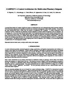
Rainbow 5 was developed by the Tokyo Fire Department. This robot is used for extinguishing fires in a fuel tank or in an industrial estate of petroleum, as it can move close to a strong fire, unlike humans. 2. Remote fire-fighting robot The remote fire-fighting robot is located at the Osaka Fire Office. This robot has the role of extinguishing strong fires when there is a possibility of an explosion. 3. Fire Search The Tokyo Fire Department developed Fire Search. In case a fireman is unable to search for survivors at the site of a fire due to heat, poisonous gas or dense smoke, Fire Search can instead find them. 4. Jet Fighter This robot was also developed by the Tokyo Fire Department. Jet Fighter has a remote controlled extinguishing system to deal with fires in tunnels and underground, where firefighters find it hard to access. LUF60 [4] was developed in Germany. LUF60 can help firefighters using unique equipment to exhaust gas or extinguish fire. This equipment is consists of hundreds of nozzles and rotates 360 degrees. These rotating nozzles can atomize a strong fog and extinguish a fire from a distance of sixty meters. In underground rooms, tunnels for trains, or any closed space with a fire, LUF60 can exhaust gas rapidly, as gas is a more serious problem compared to fires in closed places. LUF60 is now used in China and Hong Kong. There are several non-fire fighting field robots which give many clues for the development of the controller and mobile mechanism. ROB-HAZ, made in YUJINROBOT, is a well-known field robot. It can search for survivors or hazardous items such as bombs. It was used in military operations by the Zaytun troops participated in the reconstruction mission in Iraq. The Pioneer series [7], created by ActivMedia, and the PackBot [8], made by iRobot, are also well-known field robots. The Pioneer series was developed with many uses. Fig. 2 shows the schematic control structure of a Pioneer series robot. Pioneer's control structure is a distributed structure which consists of a high-level controller and a low-level controller. PackBot [8] is a military field robot. PackBot can remove mines or search for bombs during military operations. PackBot [8] can climb up stairs and overcome rocks using a variable-shape caterpillar mechanism.
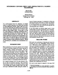
• Safety of the operator, and convenience in operation By following the above, the control architecture of the fire searching robot was designed and implemented. To accomplish the task successfully, the robot and the controller were designed based on TOD. TOD is a systematic design methodology based on the results of a concrete analysis in relation to the tasks of the robot. The underlying philosophy of TOD is to guarantee at least a set of task with high priority. And there appear many application areas where such a guarantee is crucial; fire searching robot is one of the best examples. The TOD procedure is essentially a top-down approach described in Fig. 1. By following the TOD procedure, we developed the control architecture of the fire searching robot according to the objective of the robot. The robot control architecture was designed with three components: a remote controller, a robot controller, and a wireless communication system. In this research, appropriate control architecture was designed for these three devices, and the controller was implemented by the development of suitable software and hardware. This paper is organized as follows. In Section 2, the existing field robots and their controllers are surveyed. In Section 3, the goal of the proposed fire searching robot is presented, and the robot is introduced. In Section 4, the control architecture is portrayed. Finally, the conclusions are drawn and potential further studies are mentioned in Section 5.
Figure 1. Task oriented design (TOD) procedure.
Low-Level Control : Onboard microcontroller encoder/sonar /motor-driver /battery manage/option
2. EXISTING FIELD ROBOTS In this section, several existing field robots are introduced. Initially, field robots which were developed specifically for fires are explained. In addition, other robots are investigated, as they can offer useful information even if they are not used in fires. With the result of this survey, the goal of the design is defined [1]. There have been many studies in several countries that have attempted to develop fire-fighting robots. In particular, Japan has made strides toward developing fire-fighting robots. The Japanese fire-fighting robots are as follows [2][3]. 1. Rainbow 5
RS 232C Radio Modem
High-Level Control : External computer sensor interpretation/navigation planning/mapping etc.
Figure 2. Control structure of Pioneer
3127
3. FIRE SEARCHING ROBOT 3.1 Objective Before the explanation of the control architecture design, the fire searching robot that is the target of the control architecture is briefly introduced. To design the fire searching robot, the concept of TOD was used [1]. TOD is a schematic robot design methodology based on the result of a concrete analysis about the tasks of a robot. If this concept is used to design a robot, two advantages are gained; first, the designed robot can properly perform pre-defined tasks. Second, trial and error processes generated in the design procedure can be minimized. Thus, a target analysis of the proposed fire searching robot is very important. Initially, the target environment of the proposed fire searching robot was decided to be an underground indoor fire of less than 165m2. When firefighting in this type of area, many fire-fighting organizations and fire-fighters have faced difficulties that include heavy smoke caused by the underground space, and discomfort of movement caused by the narrow and confined space. Moreover, they note frequent fire occurrences in such places. For these reasons, the fire searching robot is thought to have important functions in terms of an underground indoor fire of less than 165m2. Next, which task would be performed by the fire fighting robot in the above target environment was decided. On account of the heavy smoke and confined space, fire-fighters have difficulty receiving information regarding fire points. Hence, in underground indoor fires of less than 165m2, many fire-fighting organizations and fire-fighters hope a robot can report this information. To satisfy this requirement, the tasks of the robot were decided to be the reporting of the position of fire points in addition to the people who need to be rescued. After deciding upon the target environment and the tasks of the robot, the working scenario of the robot was constructed, and is shown in Fig. 3.
Figure 4. Fire searching robot Table 1. The specification of the fire searching robot Items Specification Total Size 900 x 650 x 370 mm Weight 100 kgf Payload 70 kgf Maximum velocity 0.5 km/h Gradability 30 ° Traction motor DC Motor Operating time 1 hr Maximum range of Visibility range 200m wireless remote control Wireless remote control Vision: RF, Data: Bluetooth The mobile element of this robot has three degrees of freedom (DOF); two DOF are for the left/right tracks and one DOF is for the auxiliary track arm. An attached camera can survey the fire conditions by using a pan-tilt unit with two DOF of motion. This fire searching robot has three special features. First, the robot system is operated by wireless remote control. Therefore, the safety of the operator is guaranteed. Second, the operator can watch the image acquired by the camera attached to the robot through a wireless image transmitter-receiver. With this function, the robot can transfer essential information: the position of the fire points and people who need to be rescued. In terms of the mechanism, the robot has a variable shape track mechanism for the supplemental tracks. Here, a variable shape track mechanism indicates that it is possible to vary the track length of the robot using the motion of the auxiliary track arm. Using this mechanism, the developed fire searching robot can climb stairways and has the advantage of being able to move in narrow and confined spaces. This characteristic of the robot is the result of TOD according to the following objectives: the robot enters a fire space through stairs and performs a searching task well in a narrow and confined indoor space.
3.2 The developed fire searching robot According to TOD procedure, the fire searching robot was developed, as shown in Fig. 4. The specifications for the robot are introduced in Table 1.
Entering through stairs
Arrival in fire space
Searching fire point
Checking the status of fire space (The people to be rescued)
Figure 3. Working scenario of the fire searching robot
3128
A. B. C. D.
4. CONTROL ARCHITECTURE The fire searching robot is operated by a remote control unit, which is shown in Fig. 5. Its control system architecture consists of three components: the remote controller, the robot controller, and the wireless communication system. Remote Controller
Wireless communication
robot arm angle robot pitch/roll angle camera pan/tilt angle velocity (translation/rotation)
Software To develop an easy-to-use Graphic User Interface (GUI) for the remote control system, the robot status data (i.e. the communication status level, robot arm angle, pitch angle, roll angle, camera angle and velocity) is considered to be presented graphically, as illustrated in Fig. 6. The client programs were written in Visual C++6.0 on a Microsoft Windows XP platform. Object oriented programming is used for the data encapsulation in each module. The remote controller software has four functions. (1) communication module (2) acquire a command from a joy-stick (3) show the captured movie from the camera (4) show the current robot status
Robot Controller
Figure 5. Conceptual diagram of the remote control The remote control unit has several types of input devices. These include a three DOF joystick to control the mobile, a two DOF joystick to control the pan/tilt unit of the camera systems, and several switches. The information gathered by these devices is transferred to the robot controller through the wireless communication system. The robot controller manages the overall robot system including the mobile, the camera systems, and all of the sensors. The robot observes the state of the fire, and gathers visual information regarding the fire using the camera system. This information is transferred to the remote controller and provided to the operator. Adopting the remote control concept has a number of advantages. One of these is the safety of the operator. A fire in an indoor space is in a hazardous environment; therefore, it is very dangerous for a person to search for another in such a place. Instead, using the fire searching robot, the operator can observe the fire while staying in a safe area through the use of the remote controller. Regarding the remote control unit, Graphic User Interface (GUI) is adopted in order to provide an operator with easy perception. There is a lot of information regarding the robot status and the fire conditions. The operator has to catch this information in one glance. The graphical representation in GUI can help the operator perceive the information easily. To achieve stable mobility of the robot, the robot controller is designed on the real time operating system. RTAI, a real time OS based on LINUX, is used for the robot controller. The following subsections from 4.1 to 4.3 explain the detail of the control architecture.
Hardware Pentium-III 1.1 GHz industrial computers function as servers that also measures and implements the control actions. The servers make use of drivers supplied by the manufacturer to access the data acquisition (DAQ) boards, RC-232C module and joystick.
Figure 6. The Graphic User Interface of the remote controller 4.2 Robot Controller Functions The Robot Controller is installed on a small PC in the robot. It has two main functions. First, it receives commands from the operator in the remote through via wireless communication and controls the robot to in order to accomplish the fire searching task. By following the operator’s commands, it controls the entire robot system including the three-DOF mobile component (left caterpillar, right caterpillar and up/down of the auxiliary track arm), and the two- DOF camera pan-tilt unit. Second, it gathers data about the posture and states of the robot through the sensors, and it also acquires the image
4.1 Remote controller Functions The remote controller software has three functions. (1) communication module A. acquire the commands for the mobile from a three-DOF joy-stick B. acquire the commands for the camera pan/tilt system from a two-DOF joy-stick C. transfer the command to the robot (2) show the captured movie from the camera (3) show the current robot status
3129
information from an IR camera. It then sends the obtained data to the remote controller.
The camera system element consists of an IR camera and a pan-tilt unit. The IR camera is mounted on the pan-tilt unit, which communicates with the PC by RS-232C. Finally, the driving component consists of the caterpillars, an auxiliary track arm and an inclination sensor. The caterpillars move the robot in order to follow a command from the remote operator and the auxiliary arm assists with the movement up and down stairs. The inclination sensor provides the pan/tilt angle of the robot body.
Control algorithm To enhance the control accuracy, the robot control system was develop based on a real-time OS, RTAI kernel patched LINUX. The control algorithm described in Fig. 7 has four states. These are a booting state, an initializing state, an emergency state and a normal state. Just after the robot is powered, the control program is started automatically. When the program begins, it initially verifies that the robot is initialized. If it is not, it initializes the mobile part of the robot, the sensors, the camera and the communication module. After the initializing state, a real-time control loop runs and it examines any abnormalities of the robot status on every sampling time. In the normal state, the robot obtains its status from sensors such as encoders, and while receiving data from the remote controller, sends the acquired data and the robot status via the wireless communication module. It operates its components (driving, camera pan-tilt unit, and other components) sequentially based on the received data. If there is an emergency signal or disconnect with the remote controller within a certain period, the program goes into the emergency state. In this state, the driving part of the robot is halted for safety considerations.
Figure 8. Hardware of the robot controller 4.3 Data communication system A 2.4GHz Bluetooth module was used for communications between the remote controller and the robot. A 900MHz RF Communication Module was used to transfer video captured by the camera.
5. CONCLUSIOIN AND FURTHER WORKS This paper presents design and implementation of control architecture for the development of fire searching robot. The fire searching robot is to gathering the information of the fires in the indoor space like as the basements of the buildings. To satisfy the target, we used the TOD methodology in the design process. Adopting remote operation concept, we divided the control architecture into three parts; the remote controller, the robot controller and the wireless communication system. To implement the controller, we developed the appropriate software and hardware for each part. The advantages of the control architecture can be arranged into three areas. First, safety of the operator is guaranteed by adopting remote control concept. Second, the remote controller is designed to help the operator perceive the information easily by using the graphical representations under GUI. Third, the robot controller is designed on the real-time OS to guarantee stable move of the robot. Nowadays, we are testing the fire searching robot with developed control system. After analyzing the result, we will develop 2nd version of the robot and control system by remedying its flaws.
Figure 7. Control algorithm Hardware The hardware of the robot controller (Fig. 8) has four components. These are a control element, a wireless communication element, a camera system element, and a driving element. In the control element, a DAQ board (Sensoray S626) is mounted in a PCI slot of a 5.25” Intel 1.4GHz Embedded PC. It has four DA channels, six encoder channels, 48 DIO channels and 16 AD channels. A Bluetooth module that sends and receives data and an RF module (900MHz) that sends images serve the wireless communication. The former is connected to the PC with the RS-232C and the latter is directly linked to the IR camera.
REFERENCES [1] P. H. Chang and H. S. Park, “Development of a Robotic Arm for Handicapped People: A Task-Oriented Design Approach,” Autonomous
3130
robots, Vol. 15, No. 1, pp. 81-92, 2003. [2] http://www.tfd.metro.tokyo.jp [3] http://www.shobo.city.nagoya.jp [4] http://www.ff-micheldorf.at/Bilder/LUF60/ [5] The Development of Advanced Robotics for the Nuclear Industry – The Development of Robotic System for the Nuclear Power Plants, Report No. KAERI/RR-1508, Korea, 1994. [6] Sungchul Kang, Woosub Lee, Munsang Kim, Kyungchul Shin, “ROBHAZ-rescue: rough-terrain negotiable teleoperated mobile robot for rescue mission,” Safety, Security and Rescue Robotics, Workshop pp. 105-110 June 2005 [7] http://www.activrobots.com/ROBOTS/specs.html
3131