FM6 150 9
CONTROL INPUT SHAPING FORCOORDINATE MEASURING MACHINES Steven D. Jones Manufacturing Systems Department Ford Motor Company Dearborn, MI
[email protected] A. Galip Ulsoy Department of Mechanical Engineering and Applied Mechanics The University of Michigan Ann Arbor, MI
[email protected]
Abstract Structural vibrations in Coordinate Measuring Machines deteriorate measurement quality at high operating speeds. In this paper, a control strategy is presented that appropriately shapes inputs to a CMM motion controller in order to avoid exciting unwanted vibrations. This control strategy utilizes a traditional bang-bang trajectory and new filtering technique called the Feedforward Filter. The control input construction takes place in the discrete time domain and can be accomplished with considerably less computational effort than currently acceptedmethods. Experimental results show that utilizing a FF Filtered trajectory results in approximately a 50% reduction in peak-to-peak magnitude of structural vibrations as compared to unshaped bang-bang trajectories.
Introduction Now, more than ever, Coordinate Measuring Machines (CMMs) are beiig integrated into mass production operations to supply dimensional feedback for near real-time process control purposes. CMMs have traditionally been viewed as low productivity, laboratory machines since their massive mechanical structures must be moved slowly to reduce the structural vibrations that result in poor measurement quality. In this paper, a motion control strategy, which reduces vibrations in CMMs that occur at higher operating speeds, is developed and experimentally evaluated . During the past decade, numerous researchers have directed their efforts to modeling flexible structures and developing control strategies to manage the complexitiesof positioning nonrigid structures such as flexible beams, robot arms, disk drive heads, etc. CMMs are a special class of robots, and nearly all of the research on flexible robots has been directed toward those with non-cartesian designs (containing at least one revolute joint). High accuracy CMMs are exclusively prismatic (three linear axes) in design so that equal spatial resolution can be maintained throughout the work zone. The basic difference in structural design has a number of significant effects on controller design. First, changes in configuration of nonXartesian robots result in large changes in inertia, while prismatic structures like
CMMs typically utilize counter balances to eliminate any effects of changing inertia with respect to the controller. Second, the vibrations that are detrimental to CMM accuracy and repeatability are usually of an order or two less in magnitude than those commonly investigated with non-Cartesian robots. In addition, the lack of accuracy or repeatability in a CMM is the result of compliance between the linear transducer and the probing mechanism, not a difference in command position and actual position, which is the focus of much of the robotics research. Finally, varying loads, which have significant effects on Controller performance in machine tools and robots, are not an issue with CMMs. Because of these differences, a CMM control strategy, called a FeedfoIwad Filter (FF Filter), that preshpes the command input to existing CMM controllers has been developed here. The preshaping strategy does not require modification of the control loop, but only a transformation of the reference or command inputs to the controller. This simple method does not require the introduction of additional sensors or actuators, and avoids the need for existing actuators to deliver forces in a frequency range coincident with the CMMs structural resonant frequency. Lately, a considerable amount of attention has been directed toward a technique for reducing structural vibrations proposed by Meckl and Seering, Singer and Seering, and Hyde and Seering [6,7,3]. This technique, called Input Command Reshaping (ICP), is based on linear systems theory and is used to shape the inputs to a system to eliminate unwanted vibration. Issues related to shaping inputs were first addressed by Smith [8] through a technique called posicast. Smith's work was later extended to systems with multiple modes by Cook [23. Aspinwall [I] investigated command shaping acceleration profiles to minimize the residual responses of flexible structures. Most recently, others have focused on further developing the work by Seering et al. [5]. CMMs are ideal candidates for application of vibration reduction strategies like ICP or FF Filtering. The.main reason is that configuration changes for well designed prismatic positioning devices, like CMMs, may not result in significant variations in resonant frequencies [4]. Another reason is that
2899
time delays, usually attributed to plant inversion strategies, do not create a problem since inputs to the system are know in advance (Le. the path program is stored in computer's memory prior to execution).
Review of Input Command Preshaping The basic idea behind Input Command Preshaping as presented by Hyde and Seering [3] is appropriately constructing inputs to a physical system with some inherent compliance to eliminate unwanted vibrations. The input commands are preshaped by constructing a series of impulses to achieve the desired response. A train of impulses can suppress residual vibration by forcing the resulting amplitude of vibration to zero. The impulse sequence for a second order system consists of an initial impulse and a second impulse of a lesser magnitude occurring at one half the damped natural frequency. The second impulse is constrained to be positive in order not to induce high stresses on the system or tax the actuators. Preshaping Robustness Issues The two impulse sequence will cancel unwanted structural vibrations when both the system damping ratio (C,) and natural frequency (a)are known exactly. In actual applications these parameters are rarely known precisely and often vary due to changes in structural configurations. The issue of robustness is addressed by differentiating the governing equations with respect to U (which may be shown to be equivalent to differentiatingwith respect to 4). Differentiation with respect to the parameters results in an input that is less sensitive to changes in the parameters, and results in the addition of a third impulse. Preshaping with Multiple Modes Often times, physical systems will have more than one structural mode that results in unwanted vibration. To address this situation, the governing equations are repeated for each individual mode.
then be B E , and the poles of the Feedforward Filter (C) may be selected to achieve the desired output. Below is the development of the simple two impulse preshaper using FF Filtering and in subsequent sections, the issues of robustness to plant uncertainties and variations are addressed. Suppose the system has undesirable poles at: s, = - @
s,
=
" + J
-60-
j
w
m
The discrete t h e equivalent of the pole location is obtained by the relationship z = PT, where T is the sampling period.
The FF Filter expressed in transfer function form is given below.
The undesirable system poles are canceled by the filter zeros, a z2 term has been introduced as required by causality, and the filter has been scaled to maintain a u i t y steady state gain. In difference equation form, the FF Filter output UFFF(n) is expressed solely as a function of the input U(n). =
U ( n )- ( z , + z , ) U ( n
- 1) + z,z,U(n
-2)
To obtain the impulse sequence described in [3] for the ICP strategy, a sampling period equal to onequarter of the damped period of oscillation is selected. A
T = " 2
The coefficients and scaling factor of Equation 1 then become:
Solving for the Command Input Sequence A solution to the set of the non-linear governing equations may be found through non-linear programming techniques. The technique for finding the impulse sequence involves selecting a time for the final impulse, dividing the total time into discrete segments, and solving for the amplitudes of the impulses at each time step. This strategy requires linearizing the non-linear equations and using a gradient search algorithm to arrive at the solution [3].
z,
+ z,
= 2
-.c e w cos(n / 2 ) =
o
and the resulting difference equation becomes:
Feedforward Filter In this section, it will be shown that ICP strategy described in the previous section is a special case of digital notch filtering.
The technique for obtaining command inputs which suppress unwanted vibrations can be viewed as a pole-zero cancellation problem. The method for determining impulse sequences is then reduced to solving algebraic expressions as opposed to complex non-linear programming techniques. The undesirable poles (A) of a system described by the transfer function (B/A) may be canceled by the zeros of a filter (NC). The transfer function between input and output would
which yields an output to an individual impulse identical to the impulse sequence presented in [3]. Feedforward Filter Robustness Issues One of the drawbacks cited for notch filtering techniques, such as the FF Filter, as a legitimate method for suppressing mechanical vibrations is that it is not robust to parameter uncertainties in the model of the system. In the ICP strategy, this issue is resolved by differentiating the governing equations
2900
position. The position of a Ch4M's moving component is measured with a linear transducer, such as glass scales, and the error between actual and command position is computed. This position error signal is multiplied by a gain and summed with the velocity command signal. The velocity servo controller has its own loop that uses feedback from a tachometer signal to maintainthe command velocity. Reshaping the command input position is realized in the following way. First, the desired displacement and corresponding acceleration are obtained. From these two values, the velocity trajectory required to obtain the motion is computed by integrating a bang-bang acceleration trajectory. The velocity trajectory is then integrated to provide the reference. position. When the FF Filter is used, the acceleration trajectory, which is proportional to the force. required to maintain the required position, is passed through the FF Filter. This filtered signal is then integrated to obtain the appropriately preshaped control input velocity and position commands.
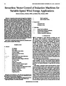
with respect to the damping ratio or natural frequency. As is shown below, in digital signal processing, this is equivalent to passing the input through the FF Filter multiple times. The concept of shaping inputs to be more robust to plant uncertainties is graphically illustrated in Figure 1. In Figure 1, the magnitude of the filtered input vs. the normalized frequency is plotted for one and two filter passes. io
i
ai
0.M
0.Wl 0.1
io
1
NarmlredFequary
Constructing a FF Filter To construct a FF Filter, it is necessary to have infoxmation about the dynamics of the non-rigid system to be controlled and information about the digital controller which will be used for controller design. The dynamics of the CMpvl which will be controlled with the FF Filter were investigated in [4]. It was shown that the vibrations in the X direction were primarily of a single mode of about 43 Hz with a damping ratio of approximately 0.011, and that varying the CMh4's configuration resulted in slight shifts of both natural frequency and damping ratio. The sampling interval which will be used in the closedloop controller design is 5 milliseconds. Using the experimentally determined natural frequency and damping ratio, the pole location of the unwanted vibration is at:
Figure 1: Magnitude Plot for One and Two Filter Passes
The plot demonstrates the robustness of the inputs to plant uncertainties due to multiple filter passes. As can be observed when comparing the magnitudes of filtered outputs, the range of frequencies attenuated increases with the number of filter passes. The FF Filter transfer function for two passes may be expressed as:
As before, selecting the sampling period to be equal to onequarter the damped period results in a filter of the form: uFRF(n)
=
U(n)+ 2KU(n
- 2 ) + K'U(n 1+2K+K2
s , ~= -3.04
- 4)
* 2681
Using the relationship z = esT,where T is the sampling interval, the zeros used to cancel the unwanted poles in the z plane are located at:
Which, when subjected to a single impulse, produces a sequence identical to the impulse sequence presented in [3].
z , , ~= 0.2254
* 0.9588J
The numerator polynomial for the filter is then:
Feedforward Filter with Multiple Modes In the ICP strategy, additional undesired modes of vibration were eliminated by simultaneously solving for repeated sets of the non-linear equations. Multiple modes of vibration may be suppressed by passing the input through multiple filters. For example, if the undesirable pole locations are at zl, z2, z3, z4, the filter design would take the following form:
'2
- 0.45082 + 0.9702
and the filter scaled for unity gain is: 0.65822'
- 0.29672 + 0.6385 Z2
where a z2 term has been introduced in the denominator due to causality, and in difference equation form:
zz ) ( z - 2 3 ) ( z - z, GppF(z) = 2(2( 1--2,z),()z( l - z , ) ( l - z3)(l - 2,)
U,(n)= 0.6582U(n)- 0.2967U(n - 1) + 0.6385U(n- 2)
Issues related to uncertainties in pole locations or variations could be addressed by applying the filter multiple times as outlined in the previous section.
(2)
Using the filter described in Equation 2 to preshape a step in acceleration, would result in a filtered sequence that is oscillatory in nature because of the negative sign preceding the
second term. These oscillations are accentuated when the step is passed through the filter twice; and when the signal is filtered more than twice, the resulting acceleration signal becomes even more oscillatory and at times requires negative forces. The filter
CMM Example A D.C. drive C m motion controller generates a voltage PrOPOfiiOnal to the Velocity required to maintain the input
2901
constructed here is a traditional notch filter. The oscillatory nature of the acceleration (force) signal would result in high fluctuating stresses in the drive-train, high demands on the motors used for positioning, and accentuate any non-linearities as a result of backlash in both the structure and the drive-train. Therefore, implementation of a notch filter for command preshaping is highly undesirable for mechanical systems like CMMs, and is the motivation for pursuing the FF Filter design. The constraint introduced by Hyde and Seering [3] on positive impulses is equivalent to constraining the numerator coefficients in Equation 3 to be non-negative. In general, the FF Filter has a transfer h c t i o n of the following form:
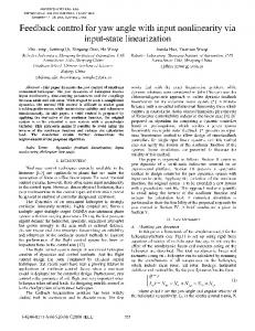
Experimental Results In this section, experimental results are presented for inputs to a CMM using the bang-bang trajectory and the FF Filter. In the experiment, the resulting vibrations will be assessed for motion along one axis of a CMM. The experimental setup, as illustrated in Figure 2, consists of four main components; an LK Micro Four CMM, a C.U.P.E. motion controller, a Wavetek Brickwall filter, and an IBM-AT computer.
To obtain non-negative coeficients, the following relationship must hold -(z,
+ z2) = e"2cos(b~) 2 o
(4)
z,z, = eLT 2 0
(5)
where a is the real part of the undesirable pole location, b is the imagimy part, and T is the sampling interval. Since the pole location of the unwanted vibration is not something which can be controlled, it is necessary to select a filter sampling interval, T, that meets the requirements in Equations 4 and 5. The quantity zlzz, is always positive, regardless of the T, so T must be selected from Equation 4. Equation 4 takes on negative values when the quantity bT is located between d 2 and 3d2 or any integer multiple of the region. In this particular case, b=268, and a filter sampling interval of 5 milliseconds is outside the desirable area. Most desirable, is a filter sampling interval as small as possible and one which is an integer multiple of the controller sampling interval. In this case, a filter sampling rate of 10 milliseconds meets both requirements. Using the filter sampling interval of 10 milliseconds for FF Filter construction, the zeros used to cancel the unwanted poles in the z plane are located at: zl,* = -0.8686 f 0.43221
The numerator polynomial for the FF Filter is then: z*
+ 1.73712 + 0.9412
and the filter scaled for unity gain is: 0 . 2 7 1 9 ~+~0.47222 + 0.2559 2 In difference equation form, the transfer function is: UFF,.(n) = 0.2719U(n)
+ 0.4722U(n - 1) + 0.2559U(n
- 2)
Using the above filter to preshape a step in acceleration eliminates the oscillatory nature of the signal that may be introduced by a traditional notch filter, and multiple filter passes do not result in oscillatory acceleration trajectories.
1(RW
f M
T
C.U.P.E.
CoMRoUER
Figure 2: Control System Experimental Setup Voltages from the C.U.P.E. controller are used to drive the D.C. motor for motion in the X direction of the Ch4M. A tachometer mounted on the drive motor produces a voltage proportional to the rotor angular velocity. The tachometer signal is low pass filtered at 100 I-IZ and sent to the A/D converter on the IBM-AT. Likewise, a signal, from an accelerometer mounted at the end of the moving arm aligned in the X direction, is low pass filtered at 100 Hz,high pass filtered at 5 Hz, and sent to the IBM-AT ADC. Displacements are measured by counting glass-scale pulses which are conditioned in the C.U.P.E. and read by a digital I/O card in the IBM-AT. The DAC on a MetraE3yte DAS-20 board in the IBM-AT is used to send analog command voltages proportional to the desired velocity to the C.U.P.E. controller. Controller Results and Interpretation In Figures 3 and 4 are acceleration profiles and measured vibrations for the bang-bang and Feedforward Filtered trajectories, respectively Note that the FF Filtered trajectory appears smoother and that it results in a 200 millisecond increase in completion time. Through experimental observations, it was found that 10 applications of the FF Filter was a good trade-off between robustness and the addition of two controller sampling periods for each filter application to the time required to complete the trajectory. Velocity trajectories sent to the controller for the bang-bang and the FF Filter were constructed by integrating the acceleration profiles with the 5 millisecond sampling interval. In Figures 3 and 4, plots of the vibration measured at the probing mechanism are shown for a configuration where the CMM arm
2902
"T
"T
2
J
4
I 5
"I U
Jm
"'T 1
a5
frf
I
O
4
s
4.5
1
*l -1.5 -e
t
1 R e (I)
(8)
Figure 3: Bang-Bang Trajectory and Measured Vibrations
Figure 4: Feedforward Filter Trajectory and Vibrations
is centrally located in the work zone. In each of the three cases experimentally evaluated (arm retracted, arm centrally located and arm extended), the amplitudes of vibration are significantly attenuated for the FF Filtered trajectory as compared to the bang-bang trajectory. The peak to peak magnitude of the vibration is reduced by approximately 50%. The experimental results do not show a complete elimination of vibration. One reason for this may be that the vibrational model only contained a single mode. A second reason may be that the non-linearities in the drive-train (such as backlash in the gears) were modeled as simple linear transformations. A third reason may be that the experimental implementation of the controller involves a zero-order-hold. For this setup, the command voltage to the velocity servo is constructed with steps in velocity (of 5 millisecond duration). These steps are equivalent to force impulses that may excite unwanted vibrations.
addressed by designing multiple FF Filters to cancel additional unwanted modes.
References [I] Aspinwall D. M., "Acceleration Profiles for Minimizing Residual Response," Journal of Dynamic Systems, Measurement and Control, Vol. 102, March, 1980. [2] Cook G. "Control of Flexible Structures via Posicast," Proceedings of the Eighteenth Southeastern Symposium on Systems Theory, April 1986, The University of Tennessee, Knoxville. [3] Hyde J. M. and Seering W., "Using Input Command Re-Shaping to Suppress Multiple Mode Vibrations," Proceedings of the E E E Conference on Robotics and Automation, April 1991, Sacramento, CA. [4] Jones S. D., Quantification and Reduction of Dynamically Induced Errors in Coordinate Measuring Machines, Ph.D. Thesis, The University of Michigan, June, 1993. [SI Khorrami F., Jain S., and Tzes A., "Adaptive Nonlinear Control and Input Preshaping for Flexible-Link Manipulators," Proceedings of the American Control Conference, 1993, San Francisco, CA. [6] Meckl P. H., and Seering W. P., "Minimizing Residual Vibration for Point-to-point Motion," Journal of Vibrations, Acoustics, Stress and Reliability in Design, October, 1985. [7]Singer N. C.,and Seering W. P., 'Reshaping Command
Conclusions Structural vibration reduction in CMMs can be realized by appropriately shaping inputs to the machine's controller. The technique shown in this paper, designated FF Filtering, was used to construct inputs to a CMM control system that resulted in a 50% reduction in peak-to-peak vibration magnitude. The FF Filter is a special digital notch filter, shown to produce impulse sequences identical to Input Command Preshaping strategies, but with considerably less computation effort. Issues related to robustness of plant variations and uncertainties were addressed by applying the FF Filter multiple times. Multiple modes are
Inputs to Reduce System Vibration," Journal of Dynamic
Systems, Measurement and Control, Vol. 112. March, 1990. [8] Smith 0. J. M., Feedback Control Systems, McGrawHill, New York, 1958, pp. 330-345.
2903