International Conference on Emerging Trends in Engineering and Technology College Of Engineering ,Teerthanker Mahaveer University
[2012]
Control of Three-Phase To Three-Phase Matrix Converter Using Carrier Based Scheme Mohd. Arif Khan
Akhilesh Kumar
Department of Electrical & Electronics Engineering, Krishna Institute of Engineering & Technology, Ghaziabad – 201206, INDIA Email:
[email protected],
[email protected] Abstract— The matrix converter has several advantages over traditional rectifier-inverter type power frequency converters. It provides sinusoidal input and output waveforms, with minimal higher order harmonics and no subharmonics; it has inherent bidirectional energy flow capability; the input power factor can be fully controlled. Last but not least, it has minimal energy storage requirements, which allows to get rid of bulky and lifetimelimited energy-storing capacitors. Various modulation schemes have been proposed for the control of matrix converters. But the explanation of matrix converter operation is complex, and so is the control methodology. In this paper a simplified carrier-based modulation scheme is proposed where the need for sector information and corresponding look-up tables is avoided. The theoretical maximum input-output voltage transfer ratio limited to 87 % for sinusoidal input and output waveforms.The simulation results are provided to validate the concept. Keywords - Matirx converter, carrier based modulation, threephase inverter, offset addition.
I. INTRODUCTION The beginnings of theMatrix Converter date back to the late 1970s [1,2]. Nowadays, the name “Matrix Converter” is used to label any power topology that can be organized into sub blocks placed in a matrix shape. In this paper “Matrix Converter” refers to the symmetrical 3×3 topology provided by nine bidirectional switches. The converter belongs to the direct frequency converter category. The output voltage is provided by direct switching of the input phases to the output phases. This means that the converter does not need a DC-link capacitor. The absence of a DC-link capacitor is one of the main advantages of the matrix converter. However it also means that the output voltage amplitude is limited by 86.6 % voltage amplitude on the input. Higher voltages can be achieved with overmodulation, which causes input current distortion. The other advantages of the converter compared to a conventional indirect frequency converter are power factor regulation; work in all four quadrants; its high dynamics; sinusoidal current consumption; nearly sinusoidal output voltage waveform, with low harmonic content and high efficiency. The main disadvantages include: number of semiconductor devices, limited output voltage amplitude, and a complicated regulation algorithm. Thus it can be made compact in size by integration of power devices into single structure and thus have the advantages of extreme temperature operation
In general, the conversion of an input ac power at a given frequency to an output power at a different frequency can be obtained with different systems, employing rotating electrical machinery, nonlinear magnetic devices or static circuits containing controllable power electronic switches. Restricting the analysis of AC/AC power frequency conversion to static circuits, the available structures can be divided in direct and indirect power conversion schemes [3]. An indirect scheme consists of two or more stages of conversion and an intermediate DC-link stage is always present. A typical example of two stage indirect AC/DC/AC power frequency conversion is the diode-bridge rectifierinverter structure, in which an AC power is firstly converted to a DC power (diode rectifier), and then converted back to an AC power at variable frequency (inverter). In direct conversion schemes a single stage carries out the AC/AC power frequency conversion. Direct static AC/AC power frequency converters basically consist of an array of static power switches connected directly between the input and output terminals. The basic operating principle is to piece together an output voltage waveform with the desired fundamental component from selected segments of the input voltage waveforms. The most-known example of this type of power frequency converter probably is the classical cycloconverter, proposed in the early 1930s [4,5]. Although the family of direct power frequency converters does not include just the cycloconverters, the following analysis will be limited to only these type of direct frequency converters. There are two types of cycloconverters, the Naturally Commutated Cycloconverter (NCC) where the switches are naturally turned-off by the voltages of the AC supply and the Forced Commutated Cycloconverter (FCC) where the turn-off of the switches is independent of the source and load voltages allowing by proper switching techniques. II. MATRIX CONVERTER – AN INTRODUCTION The Matrix Converter is a single stage converter which has an array of mxn bidirectional power switches to connect, directly, an m-phase voltage source to an n-phase load [6-12]. The Matrix Converter of 3x3 switches, shown in Fig.1, has the highest practical interest because it connects a three-phase voltage source with a three-phase load, typically a motor.
1
International Conference on Emerging Trends in Engineering and Technology College Of Engineering ,Teerthanker Mahaveer University
[2012]
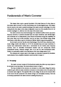
The Matrix Converter is fed by a voltage source and for this reason, the input terminals should not be short-circuited. On the other hand, the load has typically an inductive nature and for this reason an output phase must never be opened.The matrix converter is nothing but a three-phase to three-phase forced commutated cycloconverter. It consists of nine bidirectional switches that connect each output phase to each input phase, as shown in Fig. 1.
Fig. 2 general form of switching pattern
A switching-cycle average model can be derived for the matrix converter based on the three-level. The switchingcycle averaged output voltages and the input currents can be related to the input voltages and the output currents and the duty-ratio respectively, as [10] = Fig. 1 simplified circuit of a three-phase to three-phase matrix converter
Defining the switching function of a single switch as [10] Skj
= 1 Switch Skjclosed 0 Switch Skjopen
k=A,B,C j =a,b,c
j= a ,b ,c
(3)
(1)
Where A,B,C are input phase and a,b,c are output phases. The constraints discussed above can be expressed by SAj + SBj + SCj =1
=
(2)
With these restrictions, the 3x3 Matrix converter has 27 possible switching states [7]. The formulation of the simplified carrier-based modulation method is the three level representation of the matrix converter. The matrix converter consists of nine bidirectional switches. Modulating the three bi-directional switches connected to the three input phases generates an output phase voltage. At any instant, since a direct link is established between an AC voltage source and an AC current source, the connecting link should be bi-directional. To derive modulation rules, it is also necessary to consider the switching pattern that is employed. This typically follows a form similar to that shown in figure 2. The input dc voltage takes on one of the three dc values Vdc/2 , 0 and -Vdc /2 while in a matrix converter the three levels are the input three-phase voltages va, vb and vc. To synthesize the output voltage, e.g. output phase-A, the dutyratios of the three switches are daA, dbA and dcA . Similarly, the duty-ratios defined for output phase B are daB , dbB, dcB and for output phase C are daC, dbC, dcC respectively [10]
Considering a balanced three-phase system, the input voltages can be given as = = =
(4)
The duty ratios should be so chosen that the output voltage remains independent of input frequency. In other words the three-phase balanced input voltages can be considered to be in stationary reference frame and the output voltage can be considered to be in synchronous reference frame, so the that input frequency term will be absent in the output voltage [12] . Hence the duty ratios daA, dbA and dcA are chosen as = = =
ρ) ) )
(5)
With this choice of the duty-ratios, the output voltage of phase-A can be computed using (1) as
= (6) Equation (6) can be simplified as
2
International Conference on Emerging Trends in Engineering and Technology College Of Engineering ,Teerthanker Mahaveer University
= cos(ρ) term indicates that the output voltage is affected by the choice of ρ and later it will be explained that the input power factor depends on ρ . Thus, the output voltage vA is independent of the input frequency and only depends on the amplitude Vˆ of the input voltage and kA is a time-varying signal with the desired output frequency ;
;
(7) Where kB and kC are the reference output voltage modulatin signals for the output phases B and C respectively. Therefore, from (4), the output voltage in phase-A is t
(8)
Offset duty ratios should to be added [10] to the existing duty-ratios, so that the net resultant duty-ratios of individual switches are always positive. Furthermore, the offset duty-ratios should be added equally to all the output phases to ensure that the resultant output voltage vector produced by the offset duty ratios is null in the load. That is, the offset duty-ratios can only add the common-mode voltages in the output. Considering the case of output phase-A +
+
ρ) +
( t) +
)
[2012]
(13)
In any switching cycle the output phase has to be connected to any of the input phases. The summation of the duty ratios in (13) must equal unity. But the summation {D a( t )+ D b ( t ) + D c ( t )} is less than or equal to unity. Hence another offset duty-ratio (1- {D a( t )+ D b ( t ) + D c ( t )})/3 is added to D a( t), D b ( t ) and D c ( t ) in (13). The addition of this offset duty-ratio in all switches will maintain the output voltages and input currents unaffected. Similarly, the duty-ratios are calculated for the output phases B and C. If kA , kB and kc are chosen to be three phase sinusoidal references as given in (5) the input voltage capability is not fully utilized for output voltage generation. To overcome this, an additional common mode term equal to [ -{max( kA , kB, kc ) +min(kA , kB, kc)} /2] is added as in the carrier-based space-vector PWM principle as implemented in two-level inverters. Thus the amplitude of kA , kB and kc can be enhanced from 0.5 to 0.57. Thus the duty-ratios for output phase-A are modified as daA = D a( t )+ (1-{D a( t )+ D b ( t ) + D c ( t )})/3+ [ kA -{max( kA , kB, kc ) +min(kA , kB, kc)} /2] × cos (wt-ρ) dbA = D b( t )+ (1-{D a( t )+ D b ( t ) + D c ( t )})/3+ [ kA -{max( kA , kB, kc ) +min(kA , kB, kc)} /2] ×cos (wt-2π/3-ρ)
)+
dcA= D c( t )+ (1-{D a( t )+ D b ( t ) + D c ( t )})/3+ [ kA -{max( kA , kB, kc ) +min(kA , kB, kc)} /2] ×cos (wt-4π/3-ρ)
To cancel the negative components from individual duty ratios absolute value of the duty-ratios are added. Thus the minimum individual offset duty ratios should be
(14) To calculate the input power factor, the input current in a phase is represented as a function of the duty ratios and the output currents. Considering the input phase-a the input currents are synthesized by time-weighting the output currents by the duty-ratios and is given by
)=0
= ( t) =
(9)
(10)
The effective duty ratios are daA+D a (t ), dbA+D b (t) and d cA+Dc (t) The same holds good for the input phases b and c. The net duty ratio daA+D a (t ), should be accommodated within a range of 0 to 1. Thus 0 < daA+D a (t)< 1 i.e., 0< ρ) +