APPLIED PHYSICS LETTERS 97, 234103 共2010兲
Controlled microbubble generation on a compact disk Debapriya Chakraborty and Suman Chakrabortya兲 Department of Mechanical Engineering, Indian Institute of Technology Kharagpur, Kharagpur 721302, India
共Received 7 October 2010; accepted 7 November 2010; published online 7 December 2010兲 We develop a rotationally actuated fluidic device for controlled generation of microbubbles in a lab-on-a-compact-disk based environment. Use of such a strategy essentially implicates that one may employ simplistic, versatile, flexible, and economized microfabrication as well as fluidic actuation techniques, instead of more complex traditional methodologies, for microbubble generation and control. We further demonstrate that the spatio-temporal frequencies and size distributions of the generated bubbles may be judiciously controlled by simply tailoring the rotational speeds, corresponding to given channel dimensions and fluid-substrate combinations. © 2010 American Institute of Physics. 关doi:10.1063/1.3524518兴 Bubbles of micrometer length scales have far-ranging scientific and technological implications, primarily attributable to their emerging applications in the fields of food processing,1 targeted drug delivery,2,3 ultrasound imaging,4 heavy metal removal during mineral processing,5 development of bubble-based logic circuits,6 and controlled release of chemicals.7 Several approaches of microbubble generation have accordingly been investigated in the literature.8–15 The traditional methods of controlled microbubble generation often necessitate the employment of complex fluidic platforms that need to be realized through complicated and expensive fabrication techniques.8,9,15 Here, as an alternative strategy, we describe a simplistic approach for microbubble generation and manipulation, by exploiting various forces in rotationally actuated microfluidic devices 共lab-on-a-compact-disk16兲. Such devices are essentially sandwiched circular disks in which arrays of microchannels with fluidic interconnects can be laid out by simple fabrication techniques 共avoiding the routes of lithography based methods兲, and fluid can be transported through these pathways by virtue of rotational effects. Recently, compact-disk 共CD兲 based microfluidics have been demonstrated to play a promising role in the field of clinical diagnostics,17 with proven biocompatibility. From an application viewpoint, such CD based systems help in easy integration of the microfluidic functionalities18 共such as controlled droplet generation19兲 and biological protocols in a single platform.20,21 Going beyond the traditional lab-on-a-CD based arrangements, however, the present strategy additionally exploits the effects of the forces due to angular acceleration as well, for tuning the flow features. Frequency and dimensions of the bubbles generated may be explicitly controlled by designed variations of the rotational speeds for a given combination of fluids and dimensions of the pertinent fluidic pathways, thereby opening up a paradigm of rotationally actuated controlled microbubble generation. In the set of experiments reported here, silicone oil 共Fischer Scientific, USA兲 is chosen as the carrier fluid for the gas bubbles. The CD platform is essentially a disklike rotating device with a layered structure.22 The fluidic pathways embedded on the CD consist of three inlets: one for the gas
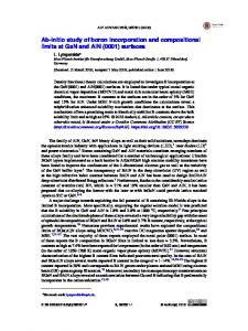
共inlet 1 in Fig. 1兲 and other two for oil 共inlet 2 and inlet 3 in Fig. 1兲. The oil starts moving from the two reservoirs to the junction located at a distance ¯x from the center of rotation, owing to the centrifugal force experienced due to difference in radial position ⌬x from the top of the reservoir to the junction. The gas also experiences centrifugal force and moves through the microchannel 1 共see Fig. 1兲. The oil is taken to be wetting in nature with respect to the channel material. Accordingly, it attempts to enter into the gas channel 1 in the limit of very low rotation speeds. As the revolution speed increases, the surface tension force and centrifugal force tend to counterbalance each other near the channeljunction. In an effort to assess the underlying consequences, one may perform an order of magnitude analysis to estimate the relative implications of various forces acting on the fluid. The pressure exerted by the centrifugal force on the carrier fluid silicone oil at the junction is given by16 ⌬Pcf = 2¯x⌬x where is the density of the carrier phase and is the rotation speed. The surface tension opposes this motion with a pressure ⌬Pst = / R 共 is the surface tension coefficient and R is the radius of the curvature of the interface兲 at the junction. The ratio of these two pressures is indicated by the parameter , as given by:  = 共⌬Pcf / ⌬Pst兲 = 2¯x⌬xR / . Other nondimensional parameters indicative of the competing effects expressed as ratio of different forces are given as:23 Ca = U / 共capillary number: the viscous force to the surface tension force兲, Re= Ul / 共Reynolds number: the inertial force to the viscous force兲, We = U2l / 共Weber number: inertial force to the surface tension force兲, and Ro = U / ¯x 共Rossby number: Coriolis force to the centrifugal
a兲
FIG. 1. 共a兲 Configuration of the bubble generation CD. 共b兲 Magnified view at the junction of microchannels 1 and 2.
Author to whom correspondence should be addressed. Electronic mail:
[email protected].
0003-6951/2010/97共23兲/234103/3/$30.00
97, 234103-1
© 2010 American Institute of Physics
234103-2
D. Chakraborty and S. Chakraborty
Appl. Phys. Lett. 97, 234103 共2010兲
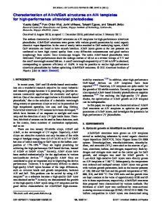
FIG. 2. 共a兲 Three regimes of two phase flow as a function of the parameter  共b兲 dimensionless time 共兲 interval between formation of subsequent bubbles and dimensionless bubble length 共r兲, as functions of the parameter , in the dripping regime.
force兲 where l and U are the characteristic length scale and velocity scales, respectively, and is the viscosity of the fluid. With parameters typical to those considered for the present problem 共silicone oil with = 963 kg/ m3, = 0.018 N / m, = 0.053 mPa s, l = 10−4 m共=R兲, ¯x = 3 cm, ⌬x = 0.5 cm, and = 500 rpm兲, the parameter  is obtained to be of order 1 共rationale behind the choice of rotational speeds conforming to such a regime is explained subsequently兲 while all the other nondimensional parameters are obtained several orders of magnitude smaller 共Ca, Re, Ro ⬃ O共10−3兲 , We = 10−6兲. However, if the sys˙ 共by temporally tem is subjected to an angular acceleration varying the rotation speeds兲, another volumetric force of the ˙ ⫻ rជ becomes important. To elucidate the underform F = lying consequences, we define a dimensionless number ˙ ¯xR2 / U depicting the ratio of the transverse driving = force due to angular acceleration to the opposing viscous resistances. turns out to be of the order unity when the angular acceleration is of the order of 100 rad/ s2. Such a delicate balance of these two opposing forces may be tactfully utilized to dictate the fluidics in CD in addition to the centrifugal force and surface tension force. When a liquid or gas is forced through a junction, two distinct modes of fluid pinch off at the junction may be observed. At low flow rates, the emerging fluid drips from the orifice 共classically known as the dripping regime兲, and at high flow rates, the liquid forms a thin stream that breaks into drops away from the orifice 共classically known as the jetting regime兲. The dripping-to-jetting transition is sharp if the liquid viscosity is significantly higher as compared to the gas viscosity. It may further be observed 关see Fig. 2共a兲兴 that for  Ⰶ 1, the surface tension dominates and the gas thread retracts from the junction without formation of bubbles. As we increase the rotational speed so that  Ⰷ 1, the gas experiences a strong centrifugal force yielding a two phase jet, which may subsequently break up into bubbles due to the Rayleigh–Plateau instability.24 The concerned method of bubble generation, however, is significantly space consuming, and hence is not commensurate with the notion of a
compact microbubble-generation technique that is envisaged here. Rather, to circumvent such constraints, we operate here in the dripping regime, with  ⬃ O共1兲. For values of the parameter  falling in this regime, the generated gas thread at the junction is not dynamically stable and breaks to yield a bubble in the channel 2. Figure 2共b兲 depicts the time interval between the subsequent bubble generations 共normalized by t0 = 3 / 2兲, as well as the length r of each bubble generated 共normalized by the width of channel 2兲, both as a functions of the parameter . It can be observed that with the increase in strength of the centrifugal force, keeping the surface tension effects invariant, the volume of each bubble increases. Hence, the dimensionless length of each bubble is proportional to  whereas the dimensionless time is found to be linear with 1 / . Because of the constraints in keeping  ⬃ O共1兲, the window of rotational speeds for bubble generation by the above mechanism appears to be rather narrow. To overcome that constraint, one may, however, employ variable rotational speeds, so as to open up a broader range of dimensions and frequencies of the bubbles consequently generated. In the subsequent discussions, we accordingly elucidate the mechanism by which this phenomenon may be realized along with varying rotational speeds 共introducing angular acceleration兲 to achieve a broader regime of controllability over the bubble size distribution and intervals between the formations of subsequent bubbles, which are otherwise difficult to implement using standard bubble generation techniques. Following this strategy, the CD is first rotated at high rotation speed n1 to enter into the centrifugal force dominated regime and is kept at that speed for a certain period of time t1, which creates a long stream of gas jet. The elongated jet has a gas core in the center with oil surrounding the same. The rotation speed is then suddenly dropped down to a speed n2 to enter into the surface tension dominating regime and is maintained at that level over a period of time t2. As the rotation speed is decreased, the dominant effect of centrifugal force is reduced. However, interestingly, another transverse force due to the angular retardation comes instantaneously into play in the
234103-3
Appl. Phys. Lett. 97, 234103 共2010兲
D. Chakraborty and S. Chakraborty
FIG. 4. Dynamically tailoring the rotational characteristics for obtaining 共a兲 variable interbubble spacing with the same bubble size and 共b兲 variable bubble sizes.
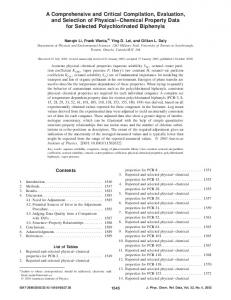
FIG. 3. Sizes of the generated microbubbles as functions of a dimensionless rotational speed, by tuning the rotation speed from the jetting regime to the surface tension regime. ⬘ is varied between 1.6⫻ 10−3 and 2.1⫻ 10−2 for all experiments.
process, which triggers a bubble snap-off process. In this process, the system switches from the centrifugal force dominated regime to surface tension dominated regime. The detached bubble moves down the channel under the effect of centrifugal force in the subsequent cycles. The length of each bubble formed in the process may be estimated by noting that the volume of the gas pinched off from the junction contributes toward formation of the entire bubble volume. In Fig. 3, we plot the normalized length of the bubble 共r兲 as a function of a parameter = An21t1 / 共where is the kinematic viscosity of the gas and A is the cross-sectional area of the end of the channel 1兲 for different values of ⬘ = An22t2 / ⬘ 共where ⬘ is the kinematic viscosity of the liquid兲. Interestingly, the parameters n2 and t2 only contribute toward dictating the spatial interval between subsequent bubbles, keeping the geometrical conformation of each bubble unaltered. Physically, and ⬘ are the indicators of the volumes of fluid emanating through the junction with cross-section A, in dimensionless forms, over the respective time intervals. It may be observed that the r versus characteristic is virtually linear, except at lower values of 共below 0.2兲. Such variations are consistent with the analytically predicted estimates for the volume flow rate of gas in a fully developed single phase flow at the end of the channel 1 under centrifugal force.25 Physically, the linear variation is justified when the jet is long enough so that the oil phase does not influence the volume flow rate of the gas at the tip of 1. For lower values of , the linearity does not hold, as attributed to the fact that the oil stream provides a back pressure on the gas jet, thereby affecting the bubble volume emerging from the junction. Further to the above considerations, we have tailored the microbubble sizes in a given period by choosing combination of parameters n1 and t1 in subsequent periods, keeping all other parameters unaltered. Analogously, to obtain microbubbles of identical dimensions but over different spatial intervals, we have varied combinations of parameters n2 and t2 in subsequent periods. Use of different rotational speeds and time intervals enable us to have externally imposed transition of the system from period-1 to period-2 behavior or further to period-p behavior, characterized by formation of p bubbles of different size in a cycle depending on the transients in the rotation speed. With rapid alterations in the rotational speed, the pinched-off fluid jet does not have enough
time to relax to a shape of its minimum energy. Accordingly, immediate changes in rotation speed split the bubble further to obtain two bubbles, generated over the same time interval, as shown in Fig. 4. In summary, we have demonstrated controlled microbubble generation, both in terms of dynamics and topology, in a lab-on-a-CD based environment. Such operations, in effect, may be dynamically programmed for several applications such as bioassays and logic programming. 1
H. A. Stone, A. D. Stroock, and A. Ajdari, Annu. Rev. Fluid Mech. 36, 381 共2004兲. K. Ferrara, R. Pollard, and M. Borden, Annu. Rev. Biomed. Eng. 9, 415 共2007兲. 3 P. Prentice, A. Cuschieri, K. Dholakia, M. Prausnitz, and P. Campbell, Nat. Phys. 1, 107 共2005兲. 4 J. R. Lindner, Nat. Rev. Drug Discovery 3, 527 共2004兲. 5 C. Oliveira, R. T. Rodrigues, and J. Rubio, Int. J. Min. Process. 96, 36 共2010兲. 6 M. Prakash and N. Gershenfeld, Science 315, 832 共2007兲. 7 H. Song, D. L. Chen, and R. F. Ismagilov, Angew. Chem., Int. Ed. 45, 7336 共2006兲. 8 P. Garstecki, I. Gitlin, W. DiLuzio, G. M. Whitesides, E. Kumacheva, and H. A. Stone, Appl. Phys. Lett. 85, 2649 共2004兲. 9 P. Garstecki, M. J. Fuerstman, H. A. Stone, and G. M. Whitesides, Lab Chip 6, 437 共2006兲. 10 A. M. Gañán-Calvo and J. M. Gordillo, Phys. Rev. Lett. 87, 274501 共2001兲. 11 J. H. Xu, S. W. Li, Y. J. Wang, and G. S. Luo, Appl. Phys. Lett. 88, 133506 共2006兲; C. Chen, Y. Zhu, P. W. Leech, and R. Manasseh, ibid. 95, 144101 共2009兲. 12 J. M. Gordillo, Z. D. Cheng, A. M. Ganan-Calvo, M. Marquez, and D. A. Weitz, Phys. Fluids 16, 2828 共2004兲. 13 T. Cubaud, M. Tatineni, X. L. Zhong, and C. M. Ho, Phys. Rev. E 72, 037302 共2005兲. 14 A. M. Gañán-Calvo, Phys. Rev. E 69, 027301 共2004兲. 15 S. L. Anna, N. Bontoux, and H. A. Stone, Appl. Phys. Lett. 82, 364 共2003兲. 16 M. Madou, J. Zoval, G. Jia, H. Kido, J. Kim, and N. Kim, Annu. Rev. Biomed. Eng. 8, 601 共2006兲. 17 M. Madou, L. Lee, S. Daunert, S. Lai, and C. Shih, Biomed. Microdevices 3, 245 共2001兲. 18 J. Ducrée, S. Haeberle, S. Lutz, S. Pausch, F. V. Stetten, and R. Zengerle, J. Micromech. Microeng. 17, S103 共2007兲. 19 S. Haeberle, R. Zengerle, and J. Ducree, Microfluid. Nanofluid. 3, 65 共2006兲. 20 J. Siegrist, R. Gorkin, M. Bastien, G. Stewart, R. Peytavi, H. Kido, M. Bergeron, and M. Madou, Lab Chip 10, 363 共2010兲. 21 R. Gorkin, J. Park, J. Siegrist, M. Amasia, B. S. Lee, J.-M. Park, J. Kim, H. Kim, M. Madouab, and Y.-K. Cho, Lab Chip 10, 1758 共2010兲. 22 See supplementary material at http://dx.doi.org/10.1063/1.3524518 for the details of the CD fabrication along with integrated experimental setup. 23 S. Chakraborty, Microfluidics and Microfabrication 共Springer, New York, 2010兲. 24 J. Plateau, Acad. Sci. Bruxelles Mem. 23, 5 共1849兲; L. Rayleigh, Proc. R. Soc. London 29, 71 共1879兲. 25 D. Chakraborty, R. Gorkin, M. Madou, L. Kulinsky, and S. Chakraborty, J. Appl. Phys. 105, 084904 共2009兲. 2