Software. Complexity. The Business Case for. Static Source Code Analysis. Ben Chelf, Coverity CTO ... Software Complexity. In many industries, software is creating a new layer of competition as companies strive to deliver more ..... Page 10 ...
of dates in 2006 was 986000 MT (Arab Agricultural Statistics. Yearbook ... plant growth regulators (Slater et al., 2003). ..... tion+to+plant+biotechnology.pdf>;2007.
email: [email protected]. Abstract ... visualization, and application of automated tools for consistency checks. ... Architecture development is done very early in the software ..... best architecture is worthless if the code does not follow itâ. In
Tom Maertens, Joris Walraevens and Herwig Bruneel. SMACS ...... hysteresis using Stochastic Petri Nets, in âProceedings of the 23rd International Conference.
able target motion caused faster movement speeds than predictable ... constant velocity (e.g., Bairstow 1987, 1988; Smeets .... function of the car's initial speed.
Dec 23, 2011 - Moreover, for two coupled resonators, we show that we can achieve light-induced ... with a varactor diode that operates in either bias-free or bi-.
All lanterns go through a metalizing process, a protective zinc layer added to ensure protection and durability against
Dec 9, 2011 ... One ClassPad 330 handheld and one. CASIO Exilim camera will be given away
during the workshop! CONFERENCE PROGRAM - FRIDAY ...
Phoenix's urban core the best destination for innovators, creatives and entrepreneurs, and ... Page 5 ..... Management E
Celebrate your season with a team night! • Discounted Lower Level and Upper
Level group ticket pricing. • Each ticket purchased for NYS Night includes certain
...
bullet holes (section 3), stabilisation, selection, and tracking of unstable optical patterns (section. 4 (a)) and elimination of spatio-temporal disorder in nonlinear ...
Jul 19, 2017 - and Teller's Desert Bus video game was intended to be bad [17]. 3. Applied Complexity ... this in the TV adaptation of. Game of Thrones [20].
New York: George Braziller; 1968. [8] Holland JH. Hidden order: how .... [42] Bale CSE, McCullen NJ, Foxon TJ, Rucklidge AM, Gale WF. Modeling diffusion of.
Jan 1, 2016 - Light Rail stations. Redevelopment Activity. Intersections with major. Issues. Parks. Third Street Study A
PROCESSES CONTROLLING THE QUANTITIES OF BIOGENIC MATERIALS. IN LAKES AND RESERVOIRS SUBJECT TO CULTURAL EUTROPHICATION by.
Selection and peer-review under responsibility of the International Scientific Committee of âThe 47th CIRP ... process and organization is mostly ignored. ... complexity patterns in value networks including production and supply chain as well as th
Helen Astill, Brian Colloty and Andrew Hall for assisting in .... of South Africa, Pretoria. Turpie, J.K., Adams, J.B., Joubert, A., Harrison, T.D., Colloty, B.M., Maree,.
Urban discourses are complex products of different actors' desires, from political to social and architectural ones. In fact the role of architectural design today is ...
Peter Robinson at the University of Hull and Henry. Merryweather of RADAN Computational Limited for their assistance and invaluable advice. This research.
of data has focused on combinations of convex losses, mostly stemming ... The joint sim- plicity of ..... envelope of l2+card(·) on a synthetic support recovery task.
May 1, 2013 - Rudolf Magnus Institute, University Medical Center Utrecht, Utrecht, The Netherlands .... Psychiatric disorders are very difficult to study in ...
Controlling Design Complexity with the Monterey Phoenix ... - Core
demonstrates how the Monterey Phoenix (MP) approach can be used to decompose a ... utilizes a commercial flight scenario to provide an example of how a ...
Complex Adaptive Systems, Publication 4 Cihan H. Dagli, Editor in Chief Conference Organized by Missouri University of Science and Technology 2014-Philadelphia, PA
Controlling Design Complexity with the Monterey Phoenix Approach Kristin Giammarco a*, Mikhail Augustona, W. Clifton Baldwinb, Ji’on Crumpb, Monica Farah-Stapletona b
a Naval Postgraduate School, Monterey, CA, USA Federal Aviation Administration, Pomona, NJ, USA
Peer-review under responsibility of scientific committee of Missouri University of Science and Technology .H\ZRUGV: architecture formal methods Monterey Phoenix behavior modeling scenario generation system of systems complex systems
1. Introduction This paper presents an approach that not only helps to alleviate the complexity inherent in the architecting process, but is also able to draw from currently accepted systems engineering diagrams. A system’s architecture serves as the bridge between requirements (or needs), and the corresponding high level design that leads to implementation (or solution) [1]. It is this highlevel design that precedes and, ideally, guides detailed solution-oriented design by providing a common mental model that can be modified via analytical tools and techniques. As modern Model-Based Systems Engineering (MBSE) approaches and tools began to be used to develop these architectures, new frameworks, notations, and entire languages began to emerge. Languages and notations (e.g., [2] [3] [4] [5] [6]) were established to provide an array of views of an architecture model, each with specific types of stakeholder concerns in mind. Architecture frameworks (e.g., [7] [8] [9] [10] [11]) were developed to group information represented in these languages and notations into standardized views, so that multiple stakeholders could more easily communicate and interact with each other, effectively using the architecture models as their Rosetta stone. All of these approaches to expressing a system’s architecture depend on a consistent, expressive underlying data model – the structure that specifies how we arrange the information about a system design. Though existing metamodels such as the DoD Architecture Framework Meta Model (DM2) [12] and the Unified Profile for DoDAF and MoDAF (UPDM) [13] may be consistent and expressive, these data models are not simple or intuitively obvious. This paper suggests a re-partitioning of the design process
1877-0509 Published by Elsevier B.V. This is an open access article under the CC BY-NC-ND license (http://creativecommons.org/licenses/by-nc-nd/3.0/). Peer-review under responsibility of scientific committee of Missouri University of Science and Technology doi:10.1016/j.procs.2014.09.080
itself to simplify the modeling of complex systems and their associated interactions and dependencies. It also proposes using Monterey Phoenix (MP) [14-18], as an extension to current approaches. MP applies a new separation of concerns, those of component behavior and component interaction, to discrete event models that previously made no such distinction. By doing so, far more behaviors are exposed prior to production and operational phases. 2. Context of MP within current behavior modeling strategies MP’s high level language is analogous to the level of abstraction represented in familiar DES modeling diagrams. For example, Functional Flow Block Diagram (FFBD) [3] and Enhanced FFBD (EFFBD) [4] notations consist of activities that are analogous to MP events, and data flows that are analogous to MP interactions. The Unified Modeling Language (UML) [5] and System Modeling Language (SysML) [6] also have activity and sequence diagrams containing discrete events and interactions with counterpart representations in MP. The concepts on the left of Table 1 are simplified in MP to improve cohesion of component behavior models while removing unnecessary coupling among those models that constrain the set of behaviors seen in simulation. This is how MP provides enhanced coverage of possible behaviors lurking in spaces that are not typically modeled using current discrete event simulation approaches. Table 1. Monterey Phoenix reduces the number of distinct concepts involved in behavior descriptions, without losing expressivity. Events and interactions represent different data model classes and relationships based on usage context. Traditional data model (DM2, UPDM) Activities / 1. “activity” if operational; “ function” if mechanized Functions 2. decomposed into other activities/functions, respectively 3. placed in sequence by position on a branch or by triggering with specific resources (inputs and outputs). Performers / 1. decomposed into other performers / components Components 2. perform the activities.
Resources / Items Needlines / Links
1. 1.
represent information, data, or tangible inputs and outputs. represent connections between performers / components, respectively.
Mapping to MP concepts Events 1. typed as activity or function as needed 2. include other events 3. “precede” other events; inputs and outputs are not separate concepts. 1. are the performer or component (hereafter Top level referred to as a component) (root) Events 2. include event compositions (activities) associated with a component. Events 1. represent operations performed on a resource. Interactions 1. represent connections between events representing components 2. used to synchronize events occurring in different components 3. specify precedence relations that involve events in multiple components.
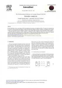
3. Novelty of Monterey Phoenix The first distinguished MP feature is the focus on behavior aspects of the system, its environment, and the interactions between them. Complexity reduction starts with reducing the number of concepts needed to build a model of the system. Instead of modeling data and control flows separately, as in the traditional architecture models, data is rendered as a set of operations performed on it. This principle is not new, and has been known as the Abstract Data Type principle since the 1970s [19]. Second, the behavior abstraction in MP is built on the simple concept of event, representing any activity performed within the system or its environment (similar to the pseudo-code concept, significantly improving readability of the models), and two basic relations between events: inclusion (IN), and precedence (PRECEDES). Behaviors of the system can be captured with event grammars containing event patterns, such as alternative, optional, and iteration. This approach provides a powerful framework for specifying hierarchical behaviors, concurrency, and the dependencies between the activities within the system, all in a simple and uniform way. Third, MP makes it possible to separate behavior models of a system’s components from the interactions between the system and its environment, providing separation of concerns, and thus simplifying system modeling. Figure 1 illustrates this approach. Each system is modeled independently, and a separate abstract interaction specification describes how those systems are woven together into a larger system of systems construct. Use case scenarios are then generated automatically, rather than attempting a laborious and error prone task of manually specifying many possible use case variants.
Figure 1. Each system’s behavior is modeled separately from system interactions. Small circles represent activities or events. All of these features yield well-structured, readable, highly reusable, and executable models of system architecture. Event grammars provide for automated generation of sets of use cases (event traces, or scenarios) representing possible behaviors of the system, including interactions between the system components and its environment. It becomes possible to devise an array of automated tools for early system architecture validation and verification on more complete sets of possible behaviors, and for automated extraction of architecture views and estimates for different stakeholders and purposes. Use of tools to automate tasks that are presently being done manually when developing a system’s architecture certainly is a step towards alleviating complexity inherent in the architecting process. It also promises a direction for dealing with the analysis of emergent behaviors of Systems of Systems that are presently excluded in manually generated traces. Early detection of design flaws is one of the most cost efficient contributions to the system development. 4. Divide and conquer: An example of using separation of concerns to partition a complex model Consider the flight scenario depicted in Figures 2a and 2b, which provide a simplistic view of an uneventful Standard Flight through the National Airspace System. This Systems Modeling Language (SysML) activity diagram spans the two figures and illustrates the sequential interactions of the passenger, the pilot (or aircraft) and the various air traffic controllers through each phase of flight, from Preflight through Landing. Continental United States flights enter the En Route phase of flight but do not necessarily enter the Oceanic phase. Consider, for example, an alternate path for flights that enter the Oceanic phase of flight. Furthermore, for simplicity, there are only two additional alternate paths in this scenario representing times when a controller may ask a pilot to enter a holding sequence: Hold in queue during the Take Off phase and Hold during the Approach phase. After the aircraft taxis to the runway, the controller may or may not issue a Ground Hold due to inclement weather conditions. Then the aircraft enters a departure queue and awaits clearance for takeoff. On approach, the controller may direct the aircraft to Hold due to congestion at the airport, the final embedded alternate path. The aircraft circles at a set location until receiving clearance to land. Of course, an actual flight would have many more alternate paths. The SysML activity diagrams in Figures 2a and 2b illustrate the flight scenario and served as the source material to express the behaviors and interactions of the MP model that follows. MP code is used to describe the behaviors and interactions of the main actors and each phase, and in doing so, segments the SysML diagram into separate models of independent behavior for each system. Then the behavior is coordinated by modeling the dependencies.
Figure 2a. Standard Flight: Preflight, Takeoff, Departure Phases
Figure 2b. Standard Flight: En Route, Descent, Approach, Landing Phases The excerpts from the MP schema Flight below illustrate the following: Each of the main flight phases in the SysML diagram, modeled as root events and decomposed into event compositions for the given phase. b) Each of the main actors in the SysML diagram, modeled as root events and decomposed into event compositions for the given actor. c) Example precedence relationships in the SysML diagram, modeled as an abstract interaction specification using the coordinate composition. a)
For brevity, the following lines of code have been condensed, and the code that specifies the overlaps between actors and phases (for instance, that event “BoardAircraft” occuring in the Preflight phase is one in the same with event “BoardAircraft” occuring in Passenger) has been omitted. Event sharing is crucial to specify, so that separate models may be coordinated and synchronized when the events are executed. The complete model and supporting information can be found on the Monterey Phoenix pages of the NPS Enterprise Wiki (https://wiki.nps.edu/). Compositions [14] [15] [16] used in the excerpts below include ordered sequence of events (A B C), selection (A | B | C), ordered iteration (* A B C *) (A B C repeated zero or more times), and composite events to encapsulate other event sets. All root events are concurrent. //----------------------------------------------------// a) main flight phases //----------------------------------------------------01 ROOT Preflight: BoardAircraft FlightCheck DepartureClearance Pushback 06 IssueGroundInstruction Taxi ; 07 ROOT Takeoff: Takeoff_preparations Liftoff Handoff_to_departure_controller; 08 Takeoff_preparations: (* Hold_in_Queue *) Clear_for_takeoff ; 11 ROOT Departure:
45 ROOT Controller: DepartureClearance IssueGroundInstruction Clear_for_takeoff 48 Handoff_to_departure_controller IssueClearances 49 Handoff_to_EnRoute_controllers 51 IssueInstruction Handoff_to_approach_controllers Clear_descent 54 Clear_approach Handoff_to_tower Clear_landing Taxi_instruction ; //----------------------------------------------------------------// c) examples of overlapping between actors and process phases //----------------------------------------------------------------60 Pilot, Preflight SHARE ALL FlightCheck, Pushback, Taxi ; 61
Pilot, Takeoff
SHARE ALL
Hold_in_Queue, Liftoff ;
62
Pilot, Departure
SHARE ALL
ChangeFrequency ;
63 Pilot, EnRoute SHARE ALL OceanicExtension, Follow_route, ChangeFrequency2 ; //--------------------------------------------------------// d) examples of coordination between phases //--------------------------------------------------------86 COORDINATE (* $x: Taxi *) FROM Preflight, 87 (* $y: Takeoff_preparations *) FROM Takeoff ADD $x PRECEDES $y ; 89 COORDINATE (* $x: Handoff_to_departure_controller ) FROM Takeoff, (* $y: ChangeFrequency *) FROM Departure ADD $x PRECEDES $y ; 90 92 COORDINATE (* $x: Maneuver_toward_Airport *) 93 (* $y: Approach_preparations *)
FROM Descent, FROM Approach
ADD $x PRECEDES $y ;
The model was executed through a prototype MP simulator, Eagle 6 [20], simulating the COORDINATE compositions with SHARE ALL compositions due to the present lack of implementation of COORDINATE in the prototype tool. The resulting output (a sample of which is shown in Figure 3) appears to provide an exhaustive (within the selected scope) set of all possible scenarios (e.g. use cases, event traces), including some unanticipated yet totally feasible behaviors. Therefore, the correct yet incomplete construction of the original SysML model was validated using the output of the MP simulation. In summary, the simulated MP results are informative to a spectrum of stakeholders by validating the scenario through formal modeling and exposing a broader range of behaviors.
Figure 3. Sample portion (first three phases) of one of 32 possible scenarios generated by Eagle 6 at scope 3 with elements positioned to reflect those in the SysML model. Solid arrows represent precedence, and dashed arrows inclusion. 5. Summary and way ahead Monterey Phoenix captures behaviors and interactions between a system and the environment, as well as the behavior of any system in that environment. It enables the early capture and refinement of design decisions, and allows one to assess and modify the design without incurring costs associated with incorrect implementations. The MP approach enables a human to more comprehensively grasp complexity, so that non-obvious behaviors lurking beneath the surface of a design are more readily exposed and understood. MP involves a re-partitioning of architecture models in a way that does not require a complete departure from existing methods, notations, frameworks or tools. Rather, it is a reinvestment of human capital in order to address the harder questions about design. This approach frees humans to address the questions that require the type of critical thinking of which only humans are capable, and to document design decisions in a very clear and concise manner that cannot be interpreted in multiple ways. Machines excel at assembling bits of precisely expressed information to compute different possible combinations or outcomes, based on human models and inputs, and verifying consistency of humans’ formal expressions. Humans complete the design loop in examining the automatically generated outputs (validation), determining what is “good” (aspects of the design to be preserved or amplified), and what is “bad” (aspects of the design to be removed or minimized). From the large number of possible scenarios automatically generated, some will contain no surprises, and some may contain unpredicted or unintended behaviors that are latent in the design. Future efforts with MP include: Identifying behavioral patterns for system-environment interactions; Determining what behaviors to abstract and what questions or groups of questions can be addressed; and Considering how visual representations, automated tools, and automated estimation methodologies can inform technical and programmatic decisions at the project, program, and enterprise level. References 1. Rozanski, N. Software Systems Architecture, Addison Wesley, 2012 2. National Institute of Standards and Technology, Draft Federal Information Processing Standards Publication 183: Integration Definition for Function Modeling (IDEF0). Gaithersburg, MD, December 21, 1993. 3. NASA, 2007, Systems Engineering Handbook, NASA/SP-2007-6105 Rev1. Washington, D.C., December 2007. 4. Long, J.E., 2000, Relationships between Common Graphical Representations Used in System Engineering, Proceedings of the SETE2000 Conference (Systems Engineering and Test and Evaluation), Brisbane, Queensland, November 15-17, 2000. 5. Booch, G., Jacobson, I., Rumbaugh, J., 2000, OMG Unified Modeling Language Specification, http://www.omg.org/docs/formal/00-03-01.pdf 6. Object Management Group, 2012, Systems Modeling Language Specification, version 1.3, http://www.omg.org/spec/SysML/1.3/PDF 7. Department of Defense, 2009, DoD Architecture Framework, Version 2.0, Washington, DC: ASD(NII)/DoD CIO. 8. Zachman, J. A. "A framework for information systems architecture." IBM systems journal 26, no. 3 (1987): 276-292. 9. Ministry of Defence, 2012, MOD Architecture Framework, retrieved June 2, 2014 from https://www.gov.uk/mod-architecture-framework. 10.North Atlantic Treaty Organization, NATO Architecture Framework version 4.0, retrieved June 2, 2014 from http://nafdocs.org/. 11.National Defence and the Canadian Armed Forces, Department of National Defence / Canadian Armed Forces Architecture Framework (DNDAF), retrieved June 2, 2014 from http://www.forces.gc.ca/en/about-policies-standards/dndaf.page. 12.Department of Defense, DoDAF Meta Model (DM2) Data Dictionary, retrieved June 2, 2014 from http://dodcio.defense.gov/TodayinCIO/DoDArchitectureFramework/dodaf20_conceptual.aspx. 13.Object Management Group, 2009, Unified Profile for DoDAF and MoDAF (UPDM), retrieved June 2, 2014 from http://www.omg.org/spec/UPDM/1.0/PDF/. 14.Auguston, M., 2009, Software Architecture Built from Behavior Models, ACM SIGSOFT Software Engineering Notes, 34:5. 15.Auguston, M., Whitcomb, C., System Architecture Specification Based on Behavior Models, in Proceedings of the 15th ICCRTS Conference (International Command and Control Research and Technology Symposium), Santa Monica, CA, June 22-24, 2010. 16.Auguston, M., Whitcomb, C., Behavior Models and Composition for Software and Systems Architecture, Proceedings of the 24th ICSSEA Conference (International Conference on Software and Systems Engineering and their Applications), Paris, France, October 23-25 2012. 17.Giammarco, K., Auguston, M., “Well, You Didn’t Say Not to! A Formal Systems Engineering Approach to Teaching an Unruly Architecture Good Behavior,” Complex Adaptive Systems Conference, Baltimore, MD, November 13 - 15, 2013. 18.Farah-Stapleton, M., Auguston, M., “Behavioral Modeling of Software Intensive System Architectures,” Complex Adaptive Systems Conference, Baltimore, MD, November 13 - 15, 2013. 19.Liskov, B., Zilles, S., 1974, Programming with abstract data types, ACM SIGPLAN Notices, Vol 9 Issue 4, pp. 50 – 59 20.Rivera Consulting Group, Eagle 6 Modeling, http://eagle6modeling.riverainc.com/, retrieved August 15, 2014.