Audio Engineering Society
Convention Paper Presented at the 121st Convention 2006 October 5–8 San Francisco, CA, USA This convention paper has been reproduced from the author's advance manuscript, without editing, corrections, or consideration by the Review Board. The AES takes no responsibility for the contents. Additional papers may be obtained by sending request and remittance to Audio Engineering Society, 60 East 42nd Street, New York, New York 10165-2520, USA; also see www.aes.org. All rights reserved. Reproduction of this paper, or any portion thereof, is not permitted without direct permission from the Journal of the Audio Engineering Society.
Linear Array Transducer Technology Andrew D. Unruh1, and Christopher J. Struck1 1
Tymphany Corporation, Cupertino, CA 95014 – USA
[email protected],
[email protected]
ABSTRACT The Linear Array Transducer (LAT) is a loudspeaker technology using multiple opposed interleaved diaphragms to create a bass transducer with a cylindrical form factor and almost no mechanical vibration. Design goals, construction and operating principles are described and frequency response and impedance measurements are shown. Recent structural improvements in the LAT are also discussed. System design considerations are discussed and examples of its use in a product are shown.
1.
INTRODUCTION
The maximum sound pressure achievable by a conventional electrodynamic loudspeaker transducer at low frequencies is a function of the maximum volume velocity, which is proportional to the effective diaphragm area multiplied by the maximum excursion and the frequency. Practical considerations, such as the suspension design, magnet and voice coil (overhung, underhung, etc.), and motor efficiency tend to limit the maximum excursion for a given cost. As a result, loudspeaker woofers that need to generate high levels of sound pressure at low frequency usually employ large diameter diaphragms. Such diaphragms are typically manufactured in a deep cone shape in order to provide rigidity and push cone resonances out of the pass band of the loudspeaker. In order to reduce the size of a low frequency transducer while maintaining equivalent performance (in terms of low frequency extension and
maximum output), a different approach is required. Getting more “bass” in less space is accomplished in the Linear Array Transducer (LAT) by redistributing the effective radiating surface area (SD) among multiple diaphragms and reducing the depth of the driver by changing the axis of motion. Here we can exploit the fact that at low frequencies where the wavelength of sound is long, radiation pattern is independent of the axis of motion. The purpose of the design is to enable low frequency sound generation to be incorporated into consumer devices where it was heretofore impossible. The characteristics of this class of products includes small size (e.g., MP-3 player docking stations), narrow (e.g., flat-panel TVs, automotive), vibration sensitivity (e.g., PCs), or all of the aforementioned. The Linear Array Transducer uses multiple, small, flat diaphragms arranged in a minimal depth, tubular form factor. The
Unruh, Struck
Linear Array Transducer Technology
2.
BASIC OPERATION
The LAT uses two motors wired so that their voice coils move toward each other with positive going voltages and away from each other with negative going voltages. One motor drives half the diaphragms which are interleaved with those driven by the other motor. Thus adjacent diaphragms move in opposition to each other to generate sound. For low frequencies, where the wavelength of sound is large relative to the length of the transducer, it will behave like a conventional dipole. The drive rods pass through holes in the opposing diaphragms that are only large enough to provide a small clearance around the rod. If the gap between the rod and the diaphragm is too large, the air leakage between the front and rear of the diaphragm increases and some low frequency output is lost.
3.
MEASUREMENTS
3.1.
Impedance and Frequency Response
Figure 2 shows the measured electrical impedance and frequency response of a LAT having six diaphragms with an effective radiating area, SD, of 525 cm2. The impedance curve shows typical loudspeaker behavior, starting low, increasing to a maximum near resonance, dropping down nearly to its DC value, and then increasing again at high frequencies. It can therefore be seen that the LAT presents essentially the same electrical load to an amplifier as a conventional driver. The frequency response is similar to that of a conventional driver with comparable SD ,and XMAX .
100
100 90
Since the motors work in opposition, the net mechanical vibration is essentially eliminated. This important feature allows the transducer to be used in situations where the transfer of mechanical vibration has deleterious effects. Another advantage of splitting the drive between two motors is that power handling is improved due to the increase in heat radiating area.
dB SPL at 1m / 2.83V
90
80 70
80
60
50
fs : Zmax : Zmin : Re : Qes : Qms : Qts :
70
60
28
Hz
47.1 Ω
40
2.55 Ω 2.18 Ω 0.45 8.45
30
0.43
20 10
50
0
10
A simplified schematic diagram of the LAT is shown in Figure 1. Arrows inside the figure by the rods indicate diaphragm motion. Arrows at the top and bottom of the figure indicate air flow.
100
1000
10000 Frequency [Hz]
Fig. 2 3.2.
Frequency response and impedance of a LAT
Small Signal Parameters
FRONT WAVE
Like conventional electrodynamic loudspeakers, the low frequency linear performance of the LAT can be characterized by its Thiele-Small or Small Signal Parameters (SSPs) [3]. Table 1 shows typical SSPs for LATs with effective piston areas of 525 and 820 cm2, respectively.
MOTOR
DIAPHRAGM RODS
MOTOR
BACK WAVE
Fig. 1 Simplified diagram of the Linear Array Transducer (LAT), showing motors, front and rear ports, and direction of air flow for indicated diaphragm motion for a LAT with four diaphragms.
The LAT incorporates holes in the diaphragms through which the drive rods pass. Alternating diaphragms are attached to a drive rod [1]. Although the tolerances in the LAT are held very tight, there is still a small air gap, and therefore there is some amount of leakage between the front and rear chambers. The amount of leakage is dependent upon the design of the LAT and of the enclosure and typically results in a slight decrease in the device’s output at low frequencies. A leakage term,
AES 121st Convention, San Francisco, CA, USA, 2006 October 5–8 Page 2 of 8
Impedance [ohms]
diaphragms are actuated so as to produce almost no mechanical vibration [1].
Unruh, Struck
Linear Array Transducer Technology
RAL, similar to an enclosure leak, can be used to model this effect [2].
LAT wired out of phase have very similar mechanical vibration.
A detailed analysis of the electrical, mechanical, and acoustic parameters of the LAT is provided in [2].
The response at the front of the figure shows vibration data for the LAT correctly operating, with the motors wired in phase. In this normal mode of operation, note that mechanically induced vibration is almost entirely canceled. This arrangement could also be exploited to enable cancellation of even-order distortion products.
Effective piston area
SD
525
820
cm2
DC Resistance
RE
3.1
3.6
Ω
Resonance Frequency
fS
28
24
Hz
Mechanical Q factor
QMS
9
3.5
Electrical Q factor
QES
0.5
0.65
Total Q factor
QTS
0.45
0.55
Force Factor
Bl
13
18
T·m
Mechanical Resistance
RMS
3
16
kg/s
Moving Mass
MMS
160
380
g
Suspension Compliance
CMS
0.21
0.12
mm/N
Equivalent Volume
VAS
81
110
liters
0.3500
0.3000
0.2500
Vibration Amplitude (g)
0.2000
0.1500
0.1000
0.0500 15" Driver 0.0000
LAT - No Opposing Motor 16
Table 1
3.3.
32
Typical LAT SSPs
64 Frequency (Hz)
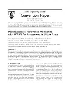
Mechanically Induced Vibration
The LAT employs two motors working in opposing directions. Each motor actuates every other diaphragm adjacent diaphragms also move in opposite directions. Because of this, mechanically induced vibration is essentially eliminated [1]. This can be a significant advantage in applications where vibration is important such as automobiles and flat panel televisions. Figure 3 compares the induced vibration measured using an accelerometer mounted on the transducer frame in the axis of diaphragm travel. The transducer was driven with a pure tone signal at several low frequencies. Vibration for a conventional 15” subwoofer is shown at the rear of the graph. Maximum acceleration is approximately 0.32 m/s2 at 64 Hz, near resonance. A LAT with similar maximum volume displacement is also shown. The response in the middle of the graph is for the LAT wired out of phase so that the motors and adjacent diaphragms all move in the same direction thus maximize mechanically induced vibration. As evidenced by this figure, a conventional driver and a
LAT - Opposing Motors 128 256
Fig. 3 Mechanical vibration of a conventional 15 inch driver (rear), a LAT wired out of phase (no vibration cancellation effect – middle), and a LAT wired with both motors in phase (front).
4.
CONSTRUCTION DETAILS
4.1.
Diaphragms
Because the diaphragms used in the LAT are small and driven closer to the periphery, they can be made flat. This results in lower stresses at high excursions, less cone break up (modal behavior), and fewer problematic resonances. In addition, the design enables the drive rods to easily attach to alternate diaphragms and to have the rods pass through neighboring diaphragms with a minimum of air leakage. Figure 4 shows a LAT diaphragm. The ridges in the diaphragm result in significantly increased rigidity while maintaining reasonably low mass. As a result, the diaphragm resonances are well beyond the intended bandwidth of the LAT itself. The three long cylindrical sleeves were
AES 121st Convention, San Francisco, CA, USA, 2006 October 5–8 Page 3 of 8
Unruh, Struck
Linear Array Transducer Technology
designed to minimize the leakage around pass-through rods between the front and rear cavities of the LAT. The three holes (found at the juncture of the ridges) serve as attachment points to the drive rods. The diaphragms are attached to the modular body sections by a rubber surround, similar to those used in conventional drivers.
Fig. 5 4.3. Fig. 4
LAT drive unit with motor and diaphragm. Body Sections
LAT Diaphragm A modular LAT body section is shown in Figure 6,
4.2.
Drive Units
The motor and magnet assemblies used in the LAT are similar to those employed in conventional drivers. Construction techniques for the drive units are therefore largely compatible with those of conventional woofers. Like most conventional woofers, the drive units of the LAT have a motor/magnet, voice coil, and spider. A drive unit and diaphragm is shown in Figure 5.
Fig. 6
LAT modular body section
The surrounds are attached to the inside of these ringshaped sections. The flange on the outside of the ring creates a surface for attaching the LAT to the enclosure as the sections are stacked together. This arrangement ensures isolation between the front and rear waves.
AES 121st Convention, San Francisco, CA, USA, 2006 October 5–8 Page 4 of 8
Unruh, Struck
Linear Array Transducer Technology
Because the body sections are reversible, only one type of body section is required to build a LAT: The orifices for the front and rear waves are created by stacking body sections rotated in the appropriate orientation. This arrangement makes the design scalable: Pairs of sections can be added or removed, increasing or decreasing the length of the device respectively. This enables trade offs between size and low frequency extension, sensitivity, and maximum output [1]. Figure 7 shows a complete assembled LAT device. This model is 12.5 cm in diameter by 38 cm in length and has the equivalent acoustic performance (in terms of maximum output / volume displacement and low frequency extension) of two conventional 10 inch woofers.
are required. Overall, the design has more parts than a conventional driver. Not all conventional materials and assembly techniques can be used. Once the modular sections are assembled, access to the inside is somewhat limited. This requires a very well thought out manufacturing, assembly, and test strategy. There will be some residual air leakage at the rod/diaphragm passthrough interfaces at low frequencies. This requires relatively high precision parts tolerances. A very slight loss in efficiency is also incurred. There can also be some noise generated when low frequency pure tone signals are played. However, this noise is low level and is generally well masked for most typical broad band program material. Mitigation methods for this are also possible.
6.
DESIGN EXAMPLES
6.1.
Sealed Box Enclosure
A system was constructed using a LAT with an effective surface area of 820 cm2. The system parameters are shown in Table 2. This unit was mounted in a 27 liter sealed enclosure. The system performance was modeled using a commercially available software package [4, 5]. The leakage of the LAT was ignored by setting the value of QL in the software to 100,000. In this case, the calculated impedance over predicts the impedance at resonance, as shown in Figure 8. By setting the value of QL to 15, the calculated and measured impedance at resonance can be made to agree well, as shown in Figure 9. With the use of a more complete blocked electrical impedance model, the measured and calculated impedance of the LAT can be predicted with very good accuracy over the entire audible frequency range [2].
Fig. 7 5.
Complete assembled LAT device. IMPLEMENTATION CHALLENGES
The design of the LAT comes at the expense of a somewhat increased manufacturing complexity and parts count. Two motors, multiple diaphragms, and rods
Figure 10 shows the measured near field frequency response as well as the frequency response as calculated in an enclosure simulation software program. The agreement between the predicted and measured responses is good at low frequencies. Ignoring the leak results in an error of less than 0.5 dB over the frequency range of interest. Much of the difference between the measured and simulated response from 80 to 300 Hz can be attributed to the difference between the measured and calculated impedance in the same frequency region. The low frequency response can be filtered in the usual
AES 121st Convention, San Francisco, CA, USA, 2006 October 5–8 Page 5 of 8
Unruh, Struck
Linear Array Transducer Technology
manner using passive, active, or digital crossover networks.
LAT Frequency Response, in 28 Liter Box 100
95
LAT Impedance, In 27 Liter Box 90 25
Sound Pressure Level, dB
85
Impedance, Ohms
20
80
75
70
15 65
60 10 55
Measured 50 10
100
5
1000
Frequency, Hz
0 10
100
1000
Fig. 10 Measured and calculated frequency response for the LAT mounted in a 27 liter sealed enclosure.
Frequency, Hz
Fig. 8 Measured and calculated LAT impedance in a 27 liter sealed enclosure. Leakage term, QL , is ignored in the calculation.
Driver Resonance
fS
29.6
Hz
Diaphragm Area
SD
820
cm2
Equivalent Volume
VAS
57.6
liters
Lower Cut Off
f3
43
Hz
Total System Q factor
QT
1.02
LAT Impedance, In 27 Liter Box 25
20
Impedance, Ohms
Table 2
Sealed enclosure system performance.
15
6.2. 10
Measured 5
0 10
100
1000
Frequency, Hz
Fig. 9 Measured and calculated LAT impedance in a 27 liter sealed enclosure with leakage term, QL accounted for in the calculation.
Band-Pass Enclosure
A second system was constructed using a LAT with an effective surface area of 525 cm2. The system parameters are shown in Table 3. The LAT was mounted in a band-pass enclosure where the volume of the sealed portion of the enclosure was 14 liters and the vented side was 15 liters. The system performance was modeled using a commercially available software package [5, 6]. The leakage of the LAT was ignored by setting the value of QL12 in the software to 100,000. In this case, the calculated impedance over predicts the impedance at the resonances, as shown in Figure 11. By setting the value of QL12 to 17, the calculated and measured impedance at resonance can be made to agree well, as shown in Figure 12. Figure 13 shows the measured near field frequency response as well as the frequency response as calculated in an enclosure simulation software program. The
AES 121st Convention, San Francisco, CA, USA, 2006 October 5–8 Page 6 of 8
Unruh, Struck
Linear Array Transducer Technology
agreement between the predicted and measured responses is good at low frequencies. Ignoring the leak results in an error of less than 0.7 dB over the frequency range of interest. Again, the low frequency response can be filtered in the usual manner using passive, active, or digital crossover networks.
LAT Frequency Response, in Bandpass Enclosure 100
90
80
Sound Pressure Level, dB
70
LAT Impedance in Bandpass Enclosure
60
Measured 50
40
30 25
20
Measured
10 20
0 10
100
1000
Impedance, Ohms
Frequency, Hz
15
Fig. 13 Measured and calculated frequency response for the LAT mounted in a band-pass enclosure.
10
5
Driver Resonance
fS
29.6
Hz
Diaphragm Area
SD
525
cm2
Equivalent Volume
VAS
60
liters
Lower Cut Off
f3L
33
Hz
Upper Cut Off
f3H
125
Hz
0 10
100
1000
Frequency, Hz
Fig. 11 Measured and calculated LAT impedance in a band-pass enclosure. Leakage term, QL12 , is ignored in the calculation. Table 3
LAT Impedance in Bandpass Enclosure
Band-pass enclosure system performance.
25
20
7.
Impedance, Ohms
Measured 15
10
5
0 10
100
1000
Frequency, Hz
Fig. 12 Measured and calculated LAT Impedance in a band-pass enclosure with leakage term, QL12, is accounted for in the calculation.
CONCLUSION
The design, operating principles, construction, and performance of the Linear Array Transducer have been presented. This transducer has a compact size and depth, and sleek form factor that enable it to be incorporated into consumer products where a conventional woofer will not fit. The LAT has a design that is both scalable and flexible which provides the ability to directly trade off length and diameter for performance in terms of maximum output (volume displacement), sensitivity, and low frequency extension. A key feature of this design is that it is essentially free of mechanical vibration. This can be critical in automotive applications or in products such as computers, televisions, portable music player docking stations, or any other device where electronics or moving parts are susceptible to damage from vibration. The device presents the same electrical load to an amplifier as a conventional driver
AES 121st Convention, San Francisco, CA, USA, 2006 October 5–8 Page 7 of 8
Unruh, Struck
Linear Array Transducer Technology
and is fully compatible with existing loudspeaker design tools such as enclosure and crossover design software.
8.
ACKNOWLEDGEMENTS
This work was supported by Tymphany Corporation. The authors would like to thank Eddie Norcott for his assistance with drawings and Van Vuong for his assistance building test enclosures. The authors would also like to thank Rich Little for his valuable editorial input. 9.
REFERENCES
[1] A. Unruh, R. True, “Loudspeaker Transducers With An Alternative Form Factor”, presented at the Audio Engineering Society 117th Convention – San Francisco, CA (2004 October 5-8). [2] A. Unruh, R. Little, C. J. Struck, A. Jabbari, J.P. Axelsson, “An Extended Small Signal Parameter Loudspeaker Model for the Linear Array Transducer”, presented at the Audio Engineering Society 121st Convention – San Francisco, CA (2006 October 5-8). [3] R. H. Small, “Direct Radiator Loudspeaker System Analysis”, J. Audio Eng. Soc., Vol. 20, No. 6 (1972 June). [4] R. H. Small, “Closed-Box Loudspeaker SystemsPart II: Synthesis”, J. Audio Eng. Soc., Vol. 21, No. 1 (1973 January). [5] K. Ougaard, “UniBox”. [6] E. R. Geddes, “An Introduction to Band-Pass Loudspeaker Systems”, J. Audio Eng. Soc., Vol. 37, No. 5 (1989 May).
AES 121st Convention, San Francisco, CA, USA, 2006 October 5–8 Page 8 of 8