In this paper, we show how a software program can be ... used for representing software programs. ... output data, behavior, sub-functions, class, and auxiliary.
Converting Programs into Cases for Software Reuse Paulo Gomes and Carlos Bento Centro de Infomática e Sistemas da Universidade de Coimbra Polo II – Pinhal de Marrocos, 3030 Coimbra, Portugal {pgomes|bento}@dei.uc.pt Abstract Developing software is a complex task. To help the user with this task, we are developing a case-based reasoning tool. Due to the dimension and complexity of software programs, acquisition of the case library is a hard task in this domain. In this paper, we show how a software program can be automatically converted into a case. Cases are described at a functional and behavioral level. The conversion rules presented here have been developed for procedural languages and enable conversion of basic language constructs into functional and behavioral knowledge.
Introduction Software programming is a hard design task, mainly due to the complexity involved in the process. Nowadays this complexity is increasing to levels in which reuse of previous software designs is very useful to short cut the development time. Case-Based Reasoning (CBR) (Kolodner 1993; Maher, Balachandran, and Zhang 1995) is a useful paradigm to develop tools for aiding software engineers in the conceptual and coding phases. Building a CBR system to do software design or just to help the software engineer in the task of program generation, passes through a first hard phase. This phase is the creation of a case library. Software programs are complex files describing what the computer system is supposed to do, and they require the software engineer to know how each language instruction works. In order to support the case library construction phase we developed generic rules to do the conversion of software files into case files. The goal of these rules is to speed up the construction of the case library, by short cutting the case acquisition phase. We also developed a case representation for software design called FunctionBehavior Case Representation (FBCR). This paper focuses on the conversion rules used for automatic case acquisition, which will be described further ahead in more detail. We also present some experimental results using the VSIC Hardware Description Language (VHDL). Copyright © 1998, American Association for Artificial Intelligence (www.aaai.org). All rights reserved.
Function-Behavior Case Representation The Function-Behavior Case Representation (FBCR) is used for representing software programs. This formalism is designed for description of procedural software languages, ranging from usual languages as C, to more specific languages, as VHDL. FBCR is derived from the StructureBehavior-Function (SBF) models developed by Goel (1992). Because software programs can be seen as designs, FBCR describes a software program at functional and behavior level. The functional level of the software program specifies the purpose of the design. The behavior level describes how the design functions are achieved by the structure. In the remaining of this section, we describe how function and behavior are represented in FBCR.
Function The functional description of a design in FBCR is represented by a tree of functions. Each node of the tree represents a function, and each link represents a partonomic relation between functions. This allows a function to be decomposed into sub-functions, providing a functional decomposition view of the design. A function is described by an identifier name, input data, output data, behavior, sub-functions, class, and auxiliary data. Input, output and auxiliary data are sets of data objects. Data objects represent memory locations and are normally language variables, constants or parameters. Data objects are defined by an identifier, a data class (for example, the variable data type) and a set of properties. Properties are described by the property name, value and units. Input and output data objects are, respectively, input and output parameters of the function. Auxiliary data represent variables and constants, local to the function. Figure 1 presents the schemas for two functions: calculator and process. Input, output and auxiliary data contain pointers to data objects. The behavior field contains a pointer to the function behaviors. Each function has a class to which it belongs. A function taxonomy makes part of the system in order to do this categorization.
Function : calculator auxiliary data :input ; result behavior :calculator_behavior sub-functions :read_input ; process; visualize class : mathematic
Function : process input :input_data output :object1 auxiliary data : ... behavior : ... sub-functions : class : process_input
Figure 1 - The representation of functions calculator and process. There are two levels of functions, corresponding to the ones that are leaves in the functional tree, and those that are not. In a higher level of abstraction, functions have a set of sub-functions, and may have a behavior graph. At the leaf level of the tree, functions do not have subfunctions, being described only by their behavior graph. A software design problem starts being described at an abstract level, down to the instruction level, and the functional description of the FBCR supports this type of representation. Functional description starts at the higher level of the functional tree, down to the behavior description. The process function in Figure 1 is at a level of abstraction bellow calculator. While the calculator function is a high level function.
Behavior The behavior of a function is described by a graph comprising nodes and edges. Each node represents a behavior state, and an edge represents a transition between states. The behavior graph represents the data object transformations, from the initial state to the final state. In the process, data object properties can be changed, or data objects can be created or eliminated. An identifier and an initial state define a behavior graph. A behavior state represents the state of the data objects in a temporal instant of the system. A behavior state is defined by an identifier and by data objects. Behavior transitions represent the causes and constraints of the state transition. An identifier, a source state, a destination state, a set of causes and a set of constraints define each behavior transition. Causes comprise primitive functions or functions. Primitive functions represent the basic elements of the programming language being represented. There are two main types of constraints: data constraints and property constraints. In the next subsection, we describe constraints and primitive functions.
Behavior Transition Labels Behavior transition labels can represent the constraints or the causes for a transition. In the first case, constraints are represented by boolean expressions that must evaluate to true in order for the transition to occur. There are two types of constraints in this category: data and property constraints. Data constraints are defined by a data object, a relational operator and a value, defining a Boolean expression. It states that the data object value must comply with the constraint defined by the relational operator and
the value. The relational operator and the value are optional; in this case, the constraint means that the data object must exist. Property constraints are defined by a data object, a property, a relational operator and a value. This type of constraint represents a limitation that the data object property must comply with. In case the relational operator and value are omitted, the constraint implies the existence of the data object property. Constraints that cause the transition are named primitive functions. These constraints are low-level functions representing language instructions, operators or predefined functions. These constraints are specific to the software language in which the program is coded. The primitive functions play an important role in the FBCR formalism, connecting the behavior level with the structural level. They make possible the conversion of behavior graphs into software programs and vice-versa.
Converting Programs to FBCR Cases Procedural programming languages have a set of basic constructs, which can be categorized in four main classes: declarations, statements, operators and sub-programs. These basic constructs are the main focus of our conversion rules. Converting programs into cases represented in FBCR is done in three different steps. The first one is the lexical analysis, which consists in the identification of the language tokens, such as literals, strings, numbers, and so on. The second step is the syntax analysis, which is the most important one. In this phase the main language constructs are identified and converted into functions, data objects, data classes and behavior graphs. In the next four sub-sections, we describe in more detail the conversion of each language construct. The third and final step comprises a coherence and consistency check of the functions, data objects, data classes and behavior graphs – the semantic analysis. The last sub-section of this section describes this process.
Declarations Declarations describe data or process structure characteristics. We consider three main kinds of declarations: variable, constant, function, and type declarations. Variable and constant declarations are converted into data objects. Declarations have an associated data type, which is converted into the data object's class. If there is an initialization value for the variable or constant, that value is transformed into the 'value' property of that object. Function or procedure declarations are converted into functions. Its parameters and return value (in case of a function) are converted into input and output data objects. This is the only knowledge that can be extracted from the function declaration, though much more can be extracted from the function's definition. Type declarations are converted into data classes. The
data classes are then associated with the data types and form a taxonomy of data classes, providing domain knowledge. An issue important regarding data classes is the insertion of the basic data classes corresponding to basic data types (like integer for instance) in the taxonomy by the knowledge engineer.
Statements
WHILE statement : WHILE (A=B) DO statements
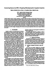
Behavior knowledge is mainly encoded in the language statements and the instruction sequence. Because each procedural language has its own instructions, we identified the main categories of statements, and we will describe how each category can be translated into the FBCR. Statements are converted into a behavior graph, which will be connected to other graphs, accordingly to the sequence of statements. The first category comprises assignment statements. These instructions assign a value to a variable. The value can be another variable, an expression, or a procedural call. Assignments in the format ’A=B’, are converted into a behavior graph with two behavior states and one transition connecting them (see Figure 2a). Data objects involved in the statement are referenced in the first state. The resulting state has the data object whose value has been modified, with the correct value. Figure 2b shows a more complex situation, where the assignment is an expression. Each operator in the expression origins a new state and transition, linked as seen in Figure 2b. Operator translation is described in the next sub-section. (a) Simple assignment situation : A = B State 1 data : A ; B
State 3 data : A (value : B+C)
Transition 1 primitive_function(+)
Transition 1 primitive_function(while) A/=B
State 1 data :
Transition 2 primitive_function(while) A=B
Statements after the W HILE
Statements inside the W HILE
Transition 3 primitive_function(while)
Figure 3 - Conversion of ’while’ and ’until’ statements. Procedural calls are a special category of language constructs. Converting procedural calls generates a behavior graph with two states and one transition linking them. Associated with the transition is a predicate that indicates that the cause of the state transition is a function, whose name is the argument of the predicate. Behavior graphs resulting from the basic statements are linked in the same order as the respective instructions sequence. The exceptions to this rule are the test, loop and some statements specific to the language, which have been described before.
Operators
Transition 1 primitive_function(=)
State 2 data : A (value : B)
(b) Expression assignment situation : A = B + C State 1 data : B ; C
the loop. The difference between the three loop types is the position of the test condition, and in the ’for’ case additional states and transitions are needed to deal with the counter variable. Figure 3 shows an example of a ’while’ loop conversion. Note that transition one links the first behavior state associated to the statements after the ’while’.
State 2 data : A ; obj1 (value : B+C)
Transition 2 primitive_function(=)
Figure 2 - Conversion of assignment statements. Test statements are the second construct category. There are two main test instructions: ’if’ and ’case’. In the first one, a test condition originates a bifurcation in the program behavior. While in the ’case’ situation there are as many alternative paths as options in the statement. Each transition has a constraint associated with the option branch. Final states are then linked to the behavior graph statements of the respective branch. Loop statements compose another category of procedural language constructs. We consider three main types of loops: ’for’, ’while’, and ’until’. Loops generate a cycle in the behavior graph, with a normal exit transition corresponding to the test condition. This test condition originates two transitions: one that goes to the beginning of the statement loop, one that goes to the next statement after
Operators are divided into four classes: logical, relational, arithmetic and sign operators. Operators are only converted when they are part of an expression in an assignment statement. In these situations, they are converted into behavior graphs. In this case we have to consider two types of operators: binary operators, and unary operators. Both types of operators are converted into a behavior graph, where the arguments correspond to data objects in the preceding state, and a new data object is created having the result of the operation. Operators are considered as primitive functions.
Sub-Programs A final group of language constructs relates to subprogram definitions. These are divided in two main types, functions and procedures. The difference is that functions always return a value, while procedures may or may not return a value. Sub-program definitions have two different parts, a declarative part and a body part. The declarative part is where the sub-program is declared, and where other declarative items are placed. Therefore, these are converted to data objects, data classes, and sub-program declarations (if there is any). Data objects are converted into input, output and auxiliary data objects accordingly to their functional role in the sub-program. Data classes are added
to the data class taxonomy, and new sub-program declarations give origin to new FBCR functions. The body part comprises the language instructions, and describes how the sub-program behaves. These instructions are converted into a behavior graph, which is then associated to the ’behavior’ field of the function in FBCR.
Semantic Analysis The last step in automatic conversion is the semantic analysis. In this step the functions, data classes, data objects and behavior graphs are checked for consistency and coherence. Some language specific checks are also made in this phase. Name checking is one of the things that is done in this phase. Mainly it consists on checking of data objects, classes or functions with the same names, and within the same scope. Another task in the semantic analysis is checking data class coherence. This is easily done by inspecting the links between different data classes. Data objects automatically created by the system must be completed with the knowledge available. For example, if a data object in a behavior state does not have a data class, the type of primitive functions and data objects responsible for its creation can be used to infer the data object class. The consistency of input, output and auxiliary data in functions must also be done. Along with the existence of the functions referenced in the behavior transitions. 18 16 14 12 10 8 6 4 2 0
Syntactic analysis
Semantic analysis
Total
1100
1000
900
800
700
600
500
400
300
200
100
0
Lexical analysis
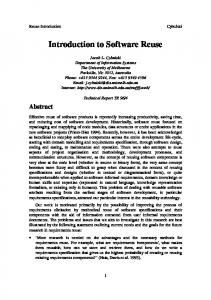
Figure 4 –Time (seconds) spent converting VHDL files, versus the number of lines of code in the VHDL file.
Experimental Results Experiments were done in the conversion of the VHDL language into FBCR. The experiments focused in speed issues regarding scalability of the proposed method. Experimental results showing the time (in seconds) spent in each conversion phase versus the number of code lines in the VHDL file appear in Figure 4.
Figure 5 shows the percentage of the total time taken by each conversion phase. 90% 80% 70% 60% 50% 40% 30% 20% 10% 0% 0
200 Lexical
400
600
800
Syntactic
1000
1200
Semantic
Figure 5 –Percentage of time that each phase takes when converting VHDL files, versus the number of code lines. These experiments were performed in a Pentium II 233MHz, with 64MB of memory running Windows NT. The conversion program, which is part of CREATOR 2, the CBR system we are developing, was implemented in C++.
Conclusions In this paper, we present a method for automated case acquisition in the domain of software design. This method converts procedural program files into cases in the FBCR. This case description language has been developed specifically for software design. The conversion method presented has been used successfully to convert files in VHDL into FBCR cases. From the experimental results we can see that the method converts 1000 lines of VHDL code in less than 16 seconds, which is much faster than a human being can do. Conversion time grows in a linear way concerning the number of lines converted. Regarding the various phases of conversion, we can see from the experimental results that with the increase of the number of lines of code the semantic analysis time decreases and the lexical analysis time increases. The syntactic analysis time decreases slightly with the number of code lines.
References Goel, A., 1992. Representation of Design Functions in Experience-Based Design. Intelligent Computer Aided Design. D. Brown, M. Waldron, H. Yosnikawa (Eds.), Elsevier Science Publishers. Kolodner, J., 1993. Case-Based Reasoning. Morgan Kaufman. Maher, M., Balachandran, M., and Zhang, D., 1995. CaseBased Reasoning in Design. Lawrence Erlbaum Associates.