European Laboratory for Particle Physics. Large Hadron ..... The helium II bayonet heat exchanger is therefore an efficient way to extract heat while using up a ...
EUROPEAN ORGANIZATION FOR NUCLEAR RESEARCH European Laboratory for Particle Physics
LHC Project Report 144 Large Hadron Collider Project
Cooling Strings of Superconducting Devices below 2 K: The Helium II Bayonet Heat Exchanger
Ph. Lebrun, L. Serio, L. Tavian and R. van Weelderen
Abstract High-energy particle accelerators and colliders contain long strings of superconducting devices - acceleration RF cavities and magnets - operating at high field, which may require cooling in helium II below 2 K. In order to maintain adequate operating conditions, the applied or generated heat loads must be extracted and transported with minimum temperature difference. Conventional cooling schemes based on conductive or convective heat transport in pressurized helium II very soon reach their intrinsic limits of thermal impedance over extended lengths. We present the concept of helium II bayonet heat exchanger, which has been developed at CERN for the magnet cooling scheme of the Large Hadron Collider (LHC), and describe its specific advantages as a slim, quasi-isothermal heat sink. Experimental results obtained on several test set-ups and a prototype magnet string have permitted to validate its performance and sizing rules, for transporting linear -1 heat loads in the W. m range over distances of several tens of meters.
* CERN LHC-ACR Division
CEC-ICMC'97 - Portland - OR - USA July 28th - August 1st 1997 Administrative Secretariat LHC Division CERN CH - 1211 Geneva 23 Switzerland Geneva, 29 September 1997
� -2-
COOLING STRINGS OF SUPERCONDUCTING DEVICES BELOW 2 K: THE HELIUM II BAYONET HEAT EXCHANGER
Ph. Lebrun, L. Serio, L. Tavian and R. van Weelderen LHC Division, CERN CH-1211 Geneva 23, Switzerland
ABSTRACT High-energy particle accelerators and colliders contain long strings of superconducting devices - acceleration RF cavities and magnets - operating at high field, which may require cooling in helium II below 2 K. In order to maintain adequate operating conditions, the applied or generated heat loads must be extracted and transported with minimum temperature difference. Conventional cooling schemes based on conductive or convective heat transport in pressurized helium II very soon reach their intrinsic limits of thermal impedance over extended lengths. We present the concept of helium II bayonet heat exchanger, which has been developed at CERN for the magnet cooling scheme of the Large Hadron Collider (LHC), and describe its specific advantages as a slim, quasi-isothermal heat sink. Experimental results obtained on several test set-ups and a prototype magnet string have permitted to validate its performance and sizing rules, for transporting linear -1 heat loads in the W. m range over distances of several tens of meters.
INTRODUCTION The basic functions of beam guiding, focusing and acceleration in high-energy particle accelerators and colliders are now performed by superconducting devices - magnets and RF cavities - in order to achieve high performance at minimum investment and operating costs. As a consequence, large-scale helium cryogenics has become a key technology in accelerator construction and operation1. The drive for higher-field, more compact machines requires to push the performance of the superconducting materials by operating at lower temperature, in particular below 2 K in superfluid helium, where the specific transport properties of the cooling medium can also be exploited for more efficient heat removal and better stabilization of the superconductors2. Historically, this argument was first applied to the cooling of large superconducting magnets, e.g. high-field solenoids and tokamak toroids, which have been successfully built and operated over the past decades3.
� -3-
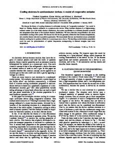
Temperature difference [K]
0.3 He II
0.25
SSC
He I 0.2 0.15
0.05
LHC
HERA Tevatron
0.1
TESLA
LEP2 Tore Supra
0 0
1
2 3 Distance [km]
4
5
Figure 1. Transport of refrigeration in large distributed cryogenic systems.
Application of helium-II cooling to particle accelerators brings an additional constraint, that of large geographic extension in one dimension, the longitudinal position along the accelerator tunnel. In both circular and linear machines, the main problem is to ensure quasi-homogeneity of temperature in long strings of superconducting devices, i.e. to extract and transport heat efficiently from the furthest magnet or RF cavity, to the refrigeration plant serving the sector (Figure 1). In such cases, the helium II bayonet heat exchanger, developed at CERN for cooling the high-field magnets of the Large Hadron 4 Collider (LHC) , represents an interesting alternative to schemes using conduction in pressurised helium II. BASIC PRINCIPLES AND DESIGN CHALLENGES Limitations of Conduction Cooling Conduction cooling in static pressurised helium II, which works well for distances in the ten-meter range, very soon reaches its limits for extended geometries. Consider a uniformly heated tubular conduit of length L, cross-section A, filled with static pressurised helium II, representing an accelerator string with linear heat load q, and transporting heat Q by Gorter-Mellink turbulent mutual friction - equivalent to a non-linear bulk conduction between temperatures Tw and Tc (Figure 2.a). He II saturated, static 1.90 K
a)
1.8 K 1.85 K He II saturated, flowing
He II pressurized, static 1.90 K
b)
1.8 K 1.85 K
Figure 2. String cooling by (a) conduction in pressurised He II and (b) He II bayonet heat exchanger
� -4From energy conservation: dQ = q ⋅ dL
(1)
From the practical conduction law:
(Q/A )n ⋅ dL = X(T + dT ) − X(T)
(2)
where the best experimental fit for n is 3.4, and X(T) is a tabulated function of temperature5, equivalent to a conductivity integral. After integration, Ln +1 ⋅ (q/A )n = (n + 1)⋅ [X(Tc ) − X(Tw )]
(3)
With a linear heat load q of 1 W.m-1, and taking Tw and Tc respectively at 1.90 and 1.85 K, the diameter of the tubular conduit, which scales as L0.65, is given in Figure 3 as a function of the conduction length. Another 0.05 K is allocated to the temperature drop across the lumped pressurised-to-saturated heat exchanger, so that the overall temperature difference between the warmest (furthest) device and the saturated heat sink is 0.10 K. 30 Conduction Bayonet HX, pressure drop Bayonet HX, velocity Bayonet HX, perimeter
25
D [cm]
20 15 10 5 0 0
50
100
150
200
L [m]
Figure 3. Sizing of conduit for string cooling by conduction in pressurised He II and bayonet heat exchanger, -1 with linear heat load of 1 W.m between 1.9 and 1.85 K.
Two-phase Flow of Saturated Helium II To overcome the above limitations, the basic idea is to distribute the pressurised-tosaturated helium heat exchanger along the length of the accelerator string (Figure 2.b). In this fashion, a quasi-isothermal heat sink is provided at every longitudinal position along the string to be cooled, and the conduction distance in pressurised helium II is typically reduced to the transverse dimension of the cryostat. Subcooled helium is expanded in the Joule-Thomson valve and transported by the small-diameter feeder pipe to the end of the heat exchanger tube, from where it flows back and gradually vaporizes as it gathers heat along the way. The string heat load is extracted across the wall of the heat exchanger tube, which provides large developed surface area and hence low transverse thermal impedance, even when its wall is partially wetted. The device constitutes a bayonet heat exchanger, requiring access only from one end, and slim enough to be easily integrated in the cold mass of the superconducting devices in the string.
� -5The basic question to be answered for ensuring adequate operation of this device, is that of stability and pattern of heated two-phase flow of helium II in horizontal or slightly inclined pipes, a subject on which no experimental data was available a few years ago. Application of predictive methods for flow-pattern maps, scaled from experimental correlations on other fluid systems6 or from simple mechanical models7, permitted to infer that the helium II heat exchanger tube would mostly operate in the stratified-flow regime, thus yielding a very partial wetting of the wall surface area. 10
Superficial liquid velocity [m/s]
Dispersed
1
Bubble
Slug
0.1
Annular Stratified Wavy Inlet
0.01
LHC Bayonet heat exchanger 0.001 0.01
Outlet 0.1
1
10
100
Superficial gas velocity [m/s]
Figure 4. Predicted working line of helium II heat exhanger tube on a scaled Mandhane, Gregory and Aziz flow pattern map (saturated helium at 1.8 K, 1.64 kPa)
A first attempt to validate the concept on a 25-mm diameter, 24-m long cylindrical 8 pipe , showed that horizontal and downward-sloping flows were very stable, the two-phases flowing clearly separated, and that excellent heat transfer at the tube wall could be obtained as long as liquid dryout did not occur. It also gave a first flavour of the control issues, in view of the slow (about 0.1 m.s-1) velocity of the liquid phase. A real helium II bayonet heat exchanger was then built and installed into two 10-m long modules containing pressurised helium II, connected in series and simulating LHC cryomagnets9. The heat exchanger consisted of a corrugated DHP copper tube, 39/44 mm in diameter and with 0.5-mm wall thickness. Tests on this set-up confirmed the stability and stratification of flow, as well as the excellent heat exchange, with conductances in the 100 W.K-1.m-1 range, up to linear heat loads of 2.4 W.m-1. Measurement of mass flow-rates and estimation of flow velocities gave access to liquid holdup, void fraction, and hence wetted area, in reasonable agreement with the heat transfer data. The bayonet heat exchanger was originally operated wetted over its whole length, with excess liquid overflowing into a phase separator vessel, where it was vaporized to subcool the incoming helium. The liquid level in this vessel, which was used to control the position of the JouleThomson valve, responded with considerable delay due to the slow velocity of the liquid flow in the heat exchanger tube, thus resulting in a difficult control problem. It was then discovered that the conduction in the pressurised helium II, although insufficient to extract the applied heat load, could be used to convey control information with little delay, and subsequent tests were performed by controlling the Joule-Thomson valve position on the temperature of the warmest magnet-simulating module, and operating the bayonet heat exchanger with its length partially wetted. Specific control tools and methods were later developed along these lines, to cope with the strong non-linearities in the system10.
� -6In complement of this application-oriented tests, more thorough investigations of twophase flow of saturated helium II were conducted at CEA Grenoble, France, on a test loop featuring 40-mm and 20-mm diameter heated cylindrical pipes, comprehensively equipped with diagnostics equipment11, 12. The diagnostics include wetted-perimeter indicators, as well as visual observation sections featuring CCD video cameras, which enabled to check the flow patterns inferred from hydraulic and thermal measurements. This work permitted to establish the validity of the stratified-flow model for predicting pressure drop, which eventually results in lack of isothermality along the flow. The liquid flow geometry - and hence the wetted perimeter - is adequately predicted by the model, which then coincides -1 with the simple, open-channel flow description, up to vapour velocities of 4 to 5 m.s . Beyond this range, an enhancement of heat transfer is observed, which cannot be explained within the stratified flow model, and is attributed to atomization of liquid droplets. This work has established a sound basis for sizing of helium II bayonet heat exchangers. Transverse Thermal Impedance of the Heat Exchanger Tube All the extracted heat has eventually to flow across the tube wall, where it encounters three thermal impedances in series: the limited solid conduction across the metal constitutive of the wall, and the Kapitza resistances produced by the refraction of thermal phonons at the metal-to-helium interfaces. The overall transverse impedance was measured on fully wetted test samples at varying temperature, so that the different temperature dependence of the solid conduction and Kapitza terms enabled to resolve them13. For tubes with a wall thickness up to about 1 mm, the Kapitza resistance largely dominates below 2 K, and the use of high-purity, cryogenic-grade copper is not required. Corrugated versus Cylindrical Tubes At equal free inner diameter, corrugated tubes exhibit, in fully developed turbulent flow, a friction factor typically 4 times larger than cylindrical, round tubes14, which results in a strong increase in pressure drop, and hence temperature inhomogeneity along the flow. This drawback is partially balanced by the fact that the particular geometry of corrugated tubes yields a higher developed heat exchanger area, and an increased wetted perimeter at low liquid level. Moreover, they show better resistance against buckling by external overpressure, and thus may be built with a thinner wall. Another interesting feature of lowlevel, open-channel flow in such tubes is that the pressure drop is produced essentially by the series of venae constrictae at the corrugations, rather than by wall friction. As a result, the average flow velocity, and hence the wetted perimeter for a given flow-rate, are independent of the slope15, which continuously varies around the LHC circumference. Practical Sizing Rules for the Bayonet Heat Exchanger Consider the case sketched in Figure 2.b, and assume the vapour flow-rate increases linearly as the liquid vaporizes along the length of the flow. From energy conservation: Q = q ⋅ L = L v ⋅ (m tot - m 0 )
(4)
where Lv is the latent heat of vaporization, mtot and m0 are the total vapour flow at outlet and inlet, respectively. Introducing x0 as the inlet vapour quality, m 0 = x 0 ⋅ m tot
(5)
A first sizing criterion is given by the allocation of a limited budget for the temperature difference along the saturated helium II flow, which translates into a maximum
� -7pressure drop. Since the void fraction in the tube is large, the pressure drop can be taken equal to that of the vapour flowing alone: dP = ψ ⋅
m2 2 ⋅ ρ ⋅ A2 ⋅ D
(6)
⋅ dL
where \ is the pipe friction factor, and U is the mass density of the vapour. After integration, for round tubes: ∆P =
8 ⋅ψ
⋅
q2
⋅
L3
⋅
1 - x 03
(7)
3 ⋅ π 2 ρ ⋅ L v 2 D 5 (1 − x 0 )3
As an example, allowing the same 0.05 K temperature drop along the string length, and with the same linear heat load of 1 W.m-1, the minimum diameter requirement set by 0.6 this criterion for a cylindrical tube scales as L and is given in Figure 3. Another sizing criterion comes from the maximum vapour velocity ensuring to remain in stratified two-phase flow, say vmax = 5 m.s-1. The tube cross-section must then satisfy: A≥
q⋅L 1 ⋅ L v ⋅ ρ ⋅ v max 1 − x 0
(8)
This criterion, which leads to a diameter scaling as L0.5, appears slightly more demanding than the pressure drop limit (see Figure 3), but still shows the clear advantage of the bayonet heat exchanger over helium II conduction. A final check of the transverse heat transfer impedance should be made, to verify that the above criteria impose a tube with sufficient perimeter. Keeping the same value of 0.05 K for the transverse temperature difference, and considering an effective wetting of 20 %, yields a minimum diameter requirement of about 1 cm for a copper tube. The helium II bayonet heat exchanger is therefore an efficient way to extract heat while using up a minimum amount of transverse space, which allows its easy implementation in the cold mass of the LHC cryomagnets (Figure 5). He II bayonet heat exchanger Magnet yoke SC windings Non-magnetic collars He vessel Thermal shield Vacuum vessel Support post
Figure 5. Transverse cross-section of LHC dipole cryomagnet, showing the helium II bayonet heat exchanger.
� -8EXAMPLES OF APPLICATION The LHC Test String The first full-scale application of the helium II bayonet heat exchanger is the LHC Test String, a fully operational model of a half-cell of the future collider16, which has been intensively tested since 1994. Over a length of 40 m, its cold mass is cooled by a helium II bayonet heat exchanger using a 41.5/50.5-mm diameter corrugated copper tube (Figure 6). To cope with uncertainty in temperature measurements, as well as to allow for residual ripple in temperature control, the difference between maximum temperature in the pressurised bath of the cryomagnets, and saturated temperature at outlet was set at 35 mK The homogeneity of temperatures along the string under steady heat load can be seen on the left part of Figure 7, with a spread of a few mK. During a current ramp, which approximately results in doubling of the heat load, the bayonet heat exchanger contains the total temperature excursion to within 5 mK. The LHC test string has accumulated 3000 hours of operation at helium II temperature, as well as 2200 powering cycles, during which the bayonet heat exchanger has maintained the magnets below 1.9 K.
Figure 6. General view of the LHC Test String.
Figure 7. Response of the LHC Test String to a current ramp (horizontal scale: time in hours, minutes).
� -9The LHC Simplified Cryogenic Distribution Scheme A recent revision of the LHC cryogenic distribution scheme has led to significant simplification, bringing the advantages of lower cost and higher reliability 17. This was achieved by extending the length of the elementary cooling loops, including the helium II bayonet heat exchangers, from 53 to 107 m. Such a change meant doubling the length and helium mass flow-rate, which would have resulted in an unacceptable eight-fold increase in pressure drop, at equal tube diameter. Since the passage available in the cold mass of the cryomagnets could not be increased, the retained solution was to install a 54-mm inner diameter, 2-mm wall thickness cylindrical tube of OFHC copper, thus trading the advantages of corrugated tubes against the reduction in friction factor. In total, the LHC will be cooled by some 230 helium II bayonet heat exchangers, distributed around its 26.7 km circumference.
REFERENCES 1. Ph. Lebrun, Cryogenic systems for accelerators, in: "Frontiers in Accelerator Technology", S.I. Kurokawa, M. Month and S. Turner, editors, World Scientific, Singapore (1996), pp. 681-700. 2. Ph. Lebrun, Superfluid helium as a technical coolant, in: "Atti XV Congresso Nazionale sulla Trasmissione del Calore", Edizioni ETS, Politecnico di Torino (1997), pp. 61-77. 3. G. Claudet and R. Aymar, Tore Supra and helium II cooling of large high-field magnets, in: "Advances in Cryogenic Engineering" Vol. 35A (1990), pp. 55-67. 4. L.R. Evans, The Large Hadron Collider project, in: "Proceedings of ICEC16/ICMC Kitakyushu", T. Haruyama, T. Mitsui and K. Yamafuji, editors, Elsevier Science, Oxford (1997), pp. 45-52. 5. G. Bon Mardion, G. Claudet and P. Seyfert, Practical data on steady-state heat transport in superfluid helium at atmospheric pressure, Cryogenics 19 (1979), pp. 45-47. 6. J.M. Mandhane, G.A. Gregory and K. Aziz, A flow pattern map for gas-liquid flow in horizontal pipes, Int. J. Multiphase Flow 1 (1974), pp. 537-553. 7. Y. Taitel and A.E. Dukler, A model for predicting flow regime transitions in horizontal and near horizontal gas-liquid flow, AIChE Journal 22:1 (1976), pp. 47-55. 8. J. Casas-Cubillos, A. Cyvoct, Ph. Lebrun, M. Marquet, L. Tavian and R. van Weelderen, Design concept and first experimental validation of the superfluid helium system for the Large Hadron Collider (LHC) project at CERN, Cryogenics 32 ICEC Supplement (1992), pp. 118-121. 9. A. Bézaguet, J. Casas-Cubillos, Ph. Lebrun, M. Marquet, L. Tavian and R. van Weelderen, The superfluid helium model cryoloop for the CERN Large Hadron Collider (LHC), in: "Advances in Cryogenic Engineering" Vol. 39A (1994), pp. 649-656. 10. B. Flemsaeter, "Contribution to the Dynamic Analysis and Optimal Control of the Superfluid Helium Cooling Loop for the LHC Magnet String", Thesis, NTU Trondheim, Norway (1995) 11. A. Gauthier, L. Grimaud, B. Rousset, A. Bézaguet and R. van Weelderen, Thermohydraulic behaviour of He II in stratified co-current two-phase flow, in: "Proceedings of ICEC16/ICMC Kitakyushu", T. Haruyama, T. Mitsui and K. Yamafuji, editors, Elsevier Science, Oxford (1997), pp. 519-522. 12. B. Rousset, A. Gauthier, L. Grimaud and R. van Weelderen, Latest developments in He II co-current twophase flow studies, paper presented at this conference. 13. M.M. Kado, Thermal conductance measurements on the LHC helium II heat exchanger pipes, CERN Report AT/95-34 (CR) (1995). 14. K. Kauder, "Strömungs- und Widerstandsverhalten in Gewellten Rohren", Thesis, Technische Universität Hannover, Germany (1971). 15. F. Déliot, private communication (1996). 16. A. Bézaguet, J. Casas-Cubillos, B. Flemsaeter, B. Gaillard-Grenadier, Th. Goiffon, H. Guinaudeau, Ph. Lebrun, M. Marquet, L. Serio, A. Suraci, L. Tavian and R. van Weelderen, The superfluid helium system for the LHC Test String. design, construction and first operation, in: "Advances in Cryogenic Engineering" Vol. 41A (1996), pp. 777-784. 17. M. Chorowski, W. Erdt, Ph. Lebrun, G. Riddone, L. Serio, L. Tavian, U. Wagner and R. van Weelderen, A simplified distribution scheme for the Large Hadron Collider, paper presented at this conference.


![[ ][ ]k [ ] [ ] [ ]2 - Core](https://m.moam.info/img/260x300/-k-2-core_5b9e9e6c097c47c8358b45a3.jpg)