Keywords: Smart Messages, Embedded Systems, Distributed Computing .... tion specific code, but SMs does not require a new programming language and ...
Cooperative Computing for Distributed Embedded Systems Cristian Borcea, Deepa Iyer, Porlin Kang, Akhilesh Saxena and Liviu Iftode Division of Computer and Information Sciences Rutgers University { borcea, iyer, kangp, saxena, iftode }@cs.rutgers.edu Abstract The next generation of computing systems will be embedded, in a virtually unbounded number, and dynamically connected. Although these systems will penetrate every possible domain of our daily life, the expectation is that they will operate outside our normal cognizance, requiring far less attention from the human users than the desktop computers today. The networked embedded computing era will challenge our ways of thinking and computing far more than the PC revolution did in the past. The current software and network architectures and their associated programming models were not designed for these scenarios. Traditional parallel and distributed computing models are based on a distribution of tasks across a stable cluster of similar processing units. In networks of embedded systems however, nodes have properties such as location or functionality that make them only partially substitutable in a specific task. Tasks need to execute on specific nodes to achieve prescribed objectives, necessitating the location of target nodes in a manner that allows partial substitution. We propose a computing model and a system architecture for distributed embedded systems where nodes “cooperate” by providing their computing and communication resources to distributed tasks. The system architecture for cooperative computing is based on Smart Messages (SM), which can be viewed as intelligent carriers of data in a network. Smart Messages are collections of code and mobile data that migrate through the network, a single network hop at a time, executing at each step. Smart Messages are responsible for their own routing. To validate the model we have implemented two previously proposed applications, Directed Diffusion and SPIN, for data collection and data dissemination in sensor networks. We have developed a simulator that executes Cooperative Computing applications and allows us to evaluate the performances by measuring both execution and communication time.
Keywords: Smart Messages, Embedded Systems, Distributed Computing
1
Introduction
The next generation of computing systems will be embedded, in a virtually unbounded number, and dynamically connected. Although these systems will penetrate every possible domain of our daily life, the expectation is that they will operate outside our normal cognizance, requiring far less attention from the human users than the desktop computers today. The first illustration of these systems that has received considerable interest in the last couple of years are networks of sensors [11, 8]. Low-power sensing devices will be used for remote monitoring and tracking tasks such as weather or traffic conditions, hospital or factory activities. Other, more hypothetical examples include disposable computers [3], by-the-yard computational fabric [2] and other massively distributed systems [21]. As the cost of embedding computing becomes negligible compared to the actual cost of goods, there will be a trend towards embedding computing capabilities into most consumer products that will make them “aware” of their usage history, functionality and surrounding objects. Food, clothing, books, people, cars, roads and buildings will be all interconnected with such technology. The networked embedded computing era will challenge our ways of thinking and computing far more than the PC revolution did in the past. The number of devices working together to achieve a common goal will be orders of magnitude greater than those seen in distributed systems today. These systems will
1
be heterogeneous in their hardware architectures, since each embedded system will typically be tailored to perform a specific task. Energy efficiency will be essential since these devices will most likely be battery powered or will obtain power from their environment, being solar- or electro-mechanically-powered. Even in situations where nodes will be non-mobile, and could potentially be connected to a permanent supply of power, the cost of electrical wiring to each node will potentially be prohibitive, and may far surpass the cost of the rest of the infrastructure. These systems will be inherently fragile, with node and link failure being the norm rather than the exception. Networked embedded systems pose a unique set of challenges. Unlike the Internet, these networks will typically be deployed in environments void of human attention, situations in which it is unacceptable to require a human to hit a “reset” button to recover from a failure. The availability of nodes may vary greatly with time, with nodes becoming unreachable due to mobility, depletion of energy resources or catastrophic failure. Traditional addressing architectures, such as IP, that provide unique addresses on a per device basis and depend on binding of properties to addresses at the time of message dispatch are inappropriate for networks of such scale and volatility. Instead, alternate addressing schemes where the binding between a desired destination and a unique name may vary over the lifetime of a message traversing the network are required. The current software and network architectures and their associated programming models were not designed for these scenarios. Traditional parallel and distributed computing models are based on a distribution of tasks across a stable cluster of similar processing units. In networks of embedded systems however, nodes have properties such as location or functionality that make them only partially substitutable in a specific task. Tasks need to execute on specific nodes to achieve prescribed objectives, necessitating the location of target nodes in a manner that allows partial substitution. Several research projects partially addressing these issues have been launched in the last couple of years [6, 8, 5, 10, 11]. Their focus has been primarily on the networking aspects of the problem, such as naming and routing, in the context of data collection applications. Our focus is on the programmability aspect of embedded system networks, namely, what is the appropriate computing model and what system support is necessary to execute user-defined applications on these networks. We believe that despite the scale and architectural and interconnection diversity of these networks, it should be possible to utilize them to perform distributed tasks, ranging from those as simple as collection, aggregation and delivery of data from sensors and routing of data traffic in the network, up to more complex tasks like collectively tracking motion across a geographical area. Individual nodes will have properties such as geographic location, motion, energy resources or hardware. For applications to be able to fully harness these unique resources, we believe that these computing elements must be programmable and support userdefined applications. However, merely providing system support for remote programmability is not enough. To benefit from programmability and from the aggregated computing resources deployed in these networks, new computing models must be employed that will necessarily be different from the traditional distributed computing models for several reasons. First, the number of devices will be orders of magnitude greater than today and addressing individual nodes will be practically impossible. Second, many of these devices will be targeted towards performing a specific task and a naming scheme based on device properties or content rather than on fixed addresses is more suitable. ”Similar” nodes may be interchangeable for a given application. Third, given the fluidity and volatility of these networks in terms of node configuration and network topology, the desired computation may never complete and partial results must be accepted. We propose a computing model and a system architecture for distributed embedded systems where nodes “cooperate” by providing their computing and communication resources to distributed tasks. The system architecture for cooperative computing is based on Smart Messages (SM), which can be viewed as intelligent carriers of data in a network. Smart Messages are collections of code and mobile data that migrate through the network, a single network hop at a time, executing at each step. Nodes in the network that support Smart Messages provide a simple, architecturally independent environment for the receipt and execution of SMs, but no routing. Thus, SMs are self-routing, namely they are responsible for determining their own paths through the network, utilizing a minimal set of facilities provided by nodes in the network. Smart Messages provide a flexible support for a wide variety of applications, ranging from data collection and dissemination, content-based routing and object tracking, to more traditional distributed computing applications in which execution of a task is spread across a collection of devices. To validate the model we have implemented two previously proposed applications [13, 11] for data collec2
tion and data dissemination in sensor networks. We have developed a simulator that executes Cooperative Computing applications and allows us to evaluate the performances by measuring both execution and communication time. Besides simulations, we are currently implementing a prototype over a network based on Bluetooth [9] short-range wireless communication. The nodes are embedded micro-controllers and PDAs running a modified version of Sun Microsystem’s KVM.
2
Related Work
Smart Messages bear some similarity to Active Messages [23], ANTS [7], Smart Packets [22], Programmable Packets [19], and Mobile Agents [24, 14, 18]. Like Active Messages, the arrival of an SM at a node leads to the execution of a task on the node. However, while Active Messages point to a handler at the destination, SMs carry code with them. Beyond the superficial similarity between the Smart Messages and Active Messages, the two models address two completely different problems. Active messages target fast communication in system-area networks and therefore, the handler execution is short and triggered as soon as the active message arrives. On the other hand, SMs target remote programmability of massive networks of embedded devices. Energy savings and quality of result are typically more important in these scenarios than performance. The ANTS [7] capsule model of programmability allows forwarding code to be carried and safely executed inside the network by a Java VM. A first difference is that this model does not migrate the execution state from node to node. It just caches and transfers code that always starts and finishes on the same node. A second difference is that ANTS targets IP networks, while SMs does not require any routing support. The main difference in terms of programmability is that, unlike capsule model, SMs define a distributed computing model where applications cooperate and synchronize each other. Smart Messages are similar to mobile agents [24, 14, 18], which also use migration of code in the network. A mobile agent may be viewed as a task that explicitly migrates from node to node assuming the underlying network assures its transport between them. Unlike mobile agents, SMs are defined to be responsible for their own routing in a network. The SM architecture further defines the infrastructure that nodes in a network supporting SMs must implement, which makes self-routing of SMs possible. The smart packet architecture [22] provides a flexible means of network management through the use of mobile code. Smart packets are implemented over IP, using the IP options header. They are routed just like other data traffic in the network, and only execute on arrival at a specific location. Unlike smart packets, SMs are executed at each hop in the network and their execution determines the next hop in the route. Unlike smart packets, SMs encapsulate the state of the application as it is executed at each hop in the network. Programmable Packets [19] are centered around a low-level packet language that adds flexibility over IP. We share some of the design goals, like safety and flexibility, that allow for in-network processing of application specific code, but SMs does not require a new programming language and provides more expressibility for user-defined applications. Research in mobile ad hoc networking [15, 4, 17, 16] and its applications [20] has resulted in numerous routing protocols for peer-to-peer multi-hop networking in infrastructures without base stations. These protocols have generally been designed for networks based on the Internet Protocol, and have primarily targeted traditional mobile computing applications such as mobile personal computers and PDAs. These protocols can be leveraged and implemented over the SM architecture. Recent work on large networks of embedded systems has focused on network protocols for wired and wireless sensor networks [8, 13, 11, 10] and system architectures for fixed-function sensor networks [12]. This research is complementary to the SM architecture. We prove in this paper that our model provides enough flexibility to enable the implementation of these models over the SM architecture.
3
Cooperative Computing
Networks of embedded systems are typically volatile configurations of programmable devices performing specific tasks and capable of short range communication. The scale and volatility of such networks make 3
traditional distributed computing models difficult, if not impossible to employ in programming them. Ad hoc approaches have been proposed for specific tasks such as data collection or dissemination. Generally, these applications are developed during network deployment phase, and after that it becomes almost impossible to modify the configuration or the protocols on individual nodes. Even if the nodes can be accessed remotely, the scale precludes any attempt to change the initial configuration. This class of applications is limited not only in terms of functionality, but also in terms of ability to allow dynamic changes or implementations of new tasks. The question that remains unanswered is whether a general solution to support user-defined distributed applications can be developed for these networks. We propose a distributed computing model for large scale ad hoc networks of embedded systems, called Cooperative Computing, based on the idea that nodes cooperate in performing a distributed task in an ad hoc manner using their local resources and properties to ”attract” tasks for computation or routing. The set of nodes involved in computation are identified by their properties, and discovered using application controlled routing. Partial execution is acceptable when a certain quality of result is met. Cooperative Computing is implemented using Smart Messages. A Smart Message (SM) is an intelligent carrier of data in the network. It migrates one network hop at a time and executes on each node in its path through the network. The execution performed at each step may differ based on particular properties of that node. For example, on nodes in the network that have sensors of interest to the SM, it may read and process sensor data. Other nodes in the network might be used as ad hoc “stepping stones” between nodes of interest. Nodes in the network cooperate in the sense that they provide SMs with an execution environment as well as a limited amount of persistent memory for a limited amount of time. In the absence of a global network topology, nodes also cooperate by transferring SMs according to SM’s own routing routines. Smart Messages along with the system support provided by nodes form the cooperative computing infrastructure that allows networks of embedded systems to execute distributed tasks.
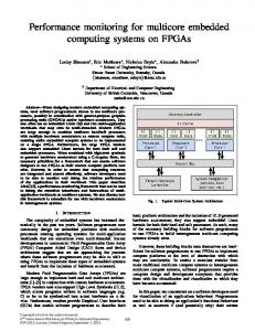
Figure 1: Cooperative Computing Example Figure 1 shows an application which can be developed using the Cooperative Computing model and Smart Messages. The application tracks object motion in a network of devices with cameras spatially distributed over a large area, for instance a campus, airport or urban highway system. This application illustrates the novel aspects of computation and communication in a wireless network of embedded devices. An SM is injected into the network to track an object with certain characteristics. The SM tries to find nodes that have acquired images of the object. The SM can use the direction of movement and geographical information to ”chase” the object. Once the SM is accepted by a node, it generates a task to further analyze
4
the object and its motion. The SM may migrate to neighboring nodes to obtain pictures of the object from a different angle and/or lighting condition, or to continue the tracking if the object is moving. In case of a positive object identification, the SM will generate a new SM that will transport the gathered information back to the node that issued the tracking.
4
Smart Messages
An SM is comprised of code and data bricks that are dynamically assembled and which are used to generate tasks on the nodes the SM visits. The SMs migrate through the network searching for target nodes and execute at each node. The nodes provide a limited data store, termed the Tag Space, which consists of tags persistent across the executions of SMs. The structure of the Tag Space is described in section 5. An SM executing at a node may access tags and may create or delete tags in the node’s tag space. Tags can also be used for naming and routing, as well as for data exchange, data sharing and synchronization between SMs. During its execution on a node in the network, an SM may spawn new SMs that may be sent out to other nodes in the network. For instance, they may collect routing information about the next node of interest. A collection of such SMs executing in a network constitutes an application.
4.1
Smart Message Format
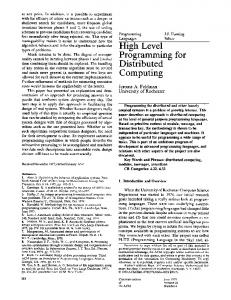
Figure 2 depicts the structure of a Smart Message. SMs are comprised of code and data sections, state, a resource table, and a handler.
Header Resource Table
Handler
State
Code
Bricks
Data
Bricks
Figure 2: Smart Message Format The SM has also a fixed size header that contains information about SM components as well as a digital signature. The digital signature identifies an SM, and is used by nodes to enforce the access of an SM to tags. The code and data sections are built from components referred to as bricks. Each code brick is an independent program that may be used together with the other code and data bricks to generate a new, possibly smaller SM. The data bricks contain mobile data that SM can access during execution. The state contains the execution context necessary for task’s resumption after a successful migration. More details about migration will be provided in subsection 6.3. The resource table consists of resource estimates: execution time, tags to be accessed or created, memory requirements, or network traffic. The resource estimates denote a bound on the expected needs of the SM at a node. At arrival, admission control is performed based on the resource table and the actual resources at the current node. Each SM carries a handler that executes immediately upon acceptance by a node. This handler decides whether the current node matches its interests or not. If the result is positive, the transfer of the SM to the current node is completed, the associated task is generated and it will be scheduled for execution as soon as possible.
4.2
Smart Message Execution
The computation of SMs is embodied in tasks that are executed on a virtual machine (VM). During its execution, a task may modify the data section of the SM as well as the local tags to which it has access, may migrate or send new SMs, and may synchronize on tags. New SMs can be always received at a node provided there are sufficient resources, but the corresponding tasks will be scheduled only after the current task completes. An executing task is never preempted by another task, but it may yield the VM by blocking on a tag pending an update by another SM. When an executing task terminates or blocks, the VM may select the
5
7
5
10
6
8
5
a 6
14
8
4
7
6
14
7
7 4
7
5
5
8 7
10
4
10 b
3
3
3
1
14
1 c
2
2
2
1
1
1 0
1
0
(a)
(b)
(c)
Figure 3: Smart Message Example next task that is ready for execution. However, if the execution time estimate based on which the SM was accepted expires, the task can be forcefully terminated. The execution of the handlers represents an exception to our run to completion model. To allow immediate and non-preemptive execution, handlers must have very short execution time. To ensure a limited and deterministic execution time, restrictions will be imposed on handlers’ code. The compiler has to verify that handlers are not using loops or backward pointers, and they do not block. Using this model we can decide fast whether an SM is transferred to destination or remains at source node. More details about this process are given in section 6.
4.3
Smart Message Self Routing
An SM is allowed to define its destination in terms of properties ( tags ). SMs are self routing since they are responsible for determining their own paths through the network. There is no system support required by SMs for routing, with the entire process taking place at application level. An SM can choose among multiple routing functions which correspond to various routing algorithms. For example, an SM may spawn SMs for route discovery, then blocks on a routing tag. When a spawned SM returns, it updates this tag and exits, causing the original SM to become unblocked. Since tags are persistent, routing information, once acquired, can be used by subsequent tasks with similar interests, thus amortizing the route discovery effort.
4.4
Smart Message Example
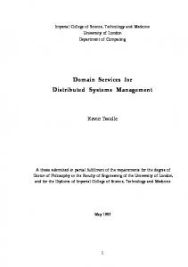
Figure 3(a) illustrates a network consisting of three types of nodes, represented by squares, circles and triangles. The nodes represented by squares are nodes of interest to an SM which is launched from the circular node in the lower left of Figure 3(a). The goal of the application implemented by this SM is to visit five square nodes and to propagate a local data item from each node to the next one visited. The numbered arrows show the path and numerical order of nodes visited by the SM. The network maintains no routing infrastructure, and the SM is responsible for determining a path to its destination, the square node numbered ’5’ in the figure. The SM may use other nodes in the network as intermediate hops as it navigates through the network. To achieve the task of information propagation, the SM must carry with it the last value it read, maintaining state as it moves from node to node through the network. Figure 3(b) shows the state of the network after the SM is done navigating the network, and thus the application it implements is complete. This SM may represent a simple object tracking application, in which the motion of the SM through the network is determined by values it reads at sensors on nodes, the SM’s path being recorded in the state of the network. A network may simultaneously contain several executing applications, as illustrated in Figure 3(c). In the figure, nodes of interest to the first application are the square nodes, and nodes exclusive to the path of this application are colored white. Nodes of interest to the second application are depicted with triangles, 6
and nodes exclusive to its path are colored black. Nodes in the network which may at some point be either part of the first or second application are colored grey. For example, the grey triangle is just a “stepping stone” on the path of the the first application, but is a node of interest to the second application. Likewise, the grey square is a node of interest to the first application but it is just an intermediate hop for the second application.
5
System Architecture
The goal of the Smart Message architecture is to keep the support required from nodes in the network to the bare minimum, placing intelligence in the SMs rather than in individual nodes. Placing intelligence in SMs, along with a common minimal system support from nodes, provides flexibility and obviates the need for the potentially impossible task of updating all nodes in a network for the implementation of a new application or protocol 1 .
Message Queue
Admission Manager
Virtual Machine
Tag Space
incoming SM
outgoing SM
Embedded System Figure 4: System Architecture The system architecture is shown in Figure 4. Nodes support Cooperative Computing by providing architecturally independent programming environments for the receipt and execution of SMs. The common minimal system support consists of: • Tag Space - is a memory region organized as a tuple space that consists of tags persistent across the execution of SMs. • Admission Manager - receives incoming messages, decides whether or not to accept them, and stores these messages into the shared Message Queue. • Virtual Machine - acts as a hardware abstraction layer for loading, scheduling, and executing tasks generated by incoming SMs
5.1
Tag Space Structure
Each node that supports SMs manages a structured memory region called the Tag Space, consisting of a limited number of tags that are persistent across the execution of SMs. Although the Tag Space provides persistent storage across SM execution, it is not specifically intended to be implemented with any particular type of storage medium, and is equally likely to be implemented with volatile RAM or non-volatile FLASH memory. 1 Some of these arguments were presented in the active networking community with modest success. Unlike in active networks, scalability is of primary importance, and partial results may be acceptable in networks of embedded systems.
7
ID
Access Control List
Lifetime
Data
Figure 5: Tag Structure
Figure 5 illustrates the structure of tags on a node. Each tag consists of an identifier, an access control list, lifetime information, and data. The identifier field is the name of the tag, and it is similar to a file name in a file system. The access of SMs to tags is restricted based on the information contained in the access control list. The tag lifetime specifies the time at which the tag will be reclaimed by the node from the Tag Space. The VM manages the Tag Space on behalf of the user applications. The VM provides support for SMs to manipulate the Tag Space. The admission manager is allowed to read the Tag Space in order to make admission control decisions. Tags may be used for a myriad of applications. They may be used to store state in a network. They may indicate the state of a node, for example a node might have a tag which represents a local sensor. Reading this tag returns a reading from the sensor, and SMs cannot delete such a tag. SMs may use tags to name nodes of interest or to store routing information. For example, SMs which are part of an application that carries data through a network may create tags at visited nodes in the network, caching discovered route information in the data portion of these tags. In this way, an application may implement traditional routing algorithms using tags to store routing tables. Tags may also be used for synchronization as mentioned in Section 4.
5.2
Admission Manager
There are two activities that the admission manager must satisfy, (1) a node must be able to accept and store new messages while the VM is executing a task, and (2) resources (energy, memory, bandwidth, etc.) on a node are limited and the manager will be required to perform admission control to prevent excessive use of resources. The manager is responsible for receiving incoming messages, and storing them into the Message Queue, subject to admission restrictions such as resource constraints, or the presence of specific tags. Each Smart Message presents its needs within its resource table. The VM makes sure that a task conforms to its declared resource estimates. Otherwise, the task can be forcefully removed from the system.
5.3
Virtual Machine
The hardware abstraction layer for the execution of SMs across different hardware platforms takes the form of a virtual machine. The requirements for the VM are that it should (1) Incur low resource overhead in terms of memory use and execution time (2) Provide an execution environment for the safe execution of migratory applications and (3) Provide the necessary primitives to support SMs. Our current implementation uses a version of the Java virtual machine, Sun Microsystem’s KVM, in the interim, modifying it to provide the necessary functionality. An important aspect of KVM is that it was designed for constrained mobile devices and its reduced size fits well our embedded systems. Using the KVM permits programming for Smart Messages to be done in Java, and thus enables harnessing well developed and supported Java application development tools and knowledge base.
6
Smart Message Life-cycle
Each SM has a well defined life-cycle. First, it has to be accepted at the destination node and to execute its handler in order to decide whether this node is suitable for its requirements. Second, if the handler returns success, a task will be generated out of SM’s code and data bricks and scheduled for execution. During its execution the SM may yield the processor and wait for data. Third, when the task completes its execution on the current node, it may decide to migrate to another node.
8
6.1
SM Admission and Handler Execution
To avoid unnecessary memory and energy consumption we define a protocol that allows only the header and the resource table to be sent to destination for admission control. If the SM admission fails, the task will be informed and the decision about next actions will be taken at the application level. If the message is accepted, our protocol will send the SM’s handler. The handler is a very restricted code brick. The VM preempts the current task and allows the handler to get executed at arrival. To preserve the non-preemptive nature of task scheduling, the handler cannot modify local tags. The only effect observed by a task is a delay due to handler execution, but the constraints imposed on handlers, defined in section 4, guarantee an upper bound for handler execution time. If the handler is successful it will trigger the transfer of the entire SM. Otherwise the task at the source node is informed. A possible optimization is to let the handler check whether code bricks belonging to its SM are already cached at local node and to transfer only those code bricks not available locally. To make this optimization possible we have to allow for code caching. A hash function applied on the code can provide statistically unique identifiers for code bricks.
6.2
Task Execution
The VM has to read the resource table of the current SM and based on the starting point specified there to generate a new task out of the SM’s code and data bricks. The data bricks contain the mobile data in the form of: variable name, variable type and value. The modified class-loader will load the task into the runtime data area according to our scheduling policy. After the loading operation is complete the virtual machine will start the execution. The execution will start from where it was left before a migration, or it will start from the beginning if this is the first hop. One of the main issues in our implementation is to design and implement an efficient SM migration mechanism. A distributed application may require synchronization during its execution. Synchronization is provided in the Cooperative Computing model through the ability for a task to block on a specific tag. In the usual case a task may want to get blocked when it does not have enough information locally and it wants to query the neighborhood. The query process is accomplished using subsequent SMs. While the task is waiting for responses, the node may execute other tasks. When an SM returns, it wakes up all tasks blocked on the updated tag and makes them ready for scheduling. The current task will resume and run to completion after this operation.
6.3
SM Migration
If the data necessary to complete the application is not available within the local Tag Space, the task may decide to migrate to another node. The VM has to perform two main operations to migrate an SM: • Save the mobile data of the current task in its associated data bricks. It is important to mention that in our implementation a task is not aware of its mobile data. The VM constructs data bricks from the mobile variables declared in each code brick. • Save all the state necessary for resumption at the destination node. We plan to implement a ”lightweight” migration that saves only a part of the entire execution state into the SM’s state. When the above operations are done, the SM is sent to destination and resumed there, while the local VM will schedule a new task.
7
Programming Interface
Cooperative Computing will allow a programmer to describe a distributed application in terms of computation and migration phases. To alleviate the issues introduced by distributed programming on large scale, volatile networks we need to carefully design our programming interface. Previous attempts [7, 19, 22] have been made to design languages or APIs suitable for in-network processing of application specific code, but 9
their limited expressibility makes difficult to imagine how to use them for more general distributed programs. Implementing such applications requires a simple, yet flexible programming interface. We expose to applications a programming interface divided into four categories based on the functionality exhibited by its primitives. These categories are depicted in figure 6. Application
Routing
Tag Space SM Operations Construction
Communication Synchronization
Figure 6: Programming Interface Structure The applications and the application level routing perform computation using data stored in Tag Space, assembly new SMs out of its code and data bricks, send SMs or migrate toward desired destinations, and synchronize on tags. The API primitives are presented in table 1: Category Tag Space Operations Construction Communication Synchronization
Primitives createTag, deleteTag, getTag, putTag constructSM sendSM blockSM
Table 1: API primitives The operations on Tag Space allow an SM to create/delete or access existing tags. The VM enforces the access control and makes sure that an SM does not attempt to use tags not declared in the resource table. An SM may decide at any point during the execution to spawn a new SM using its code and data bricks. The constructSM primitive performs the assembly actions. To limit resource usage throughout the network for a malicious or wrong application, a possible field in the resource table is the number of SMs to be spawned. After each construction this value can be divided among the parent and the child SM. To send new SMs in the network or to migrate itself to the next hop, an SM uses sendSM. The implementation of sendSM is done on top of a communication interface that presents a common view of the network despite the heterogeneous network interfaces and communication protocols encountered. The entire protocol of sending an SM described in subsection 6.1 is implemented in this function. A task may decide to completely migrate to another node or to migrate its computation to one or more neighbors and to continue its execution on the local node. In the last case, the return value of send is used to discriminate among the local task and its computation shipped to other nodes. Distributed computing requires synchronization mechanisms to allow cooperation among applications or different threads of executions of an application. Our update based synchronization mechanism is implemented by blockSM primitive. To avoid possible deadlocks due to lost SMs ( i.e. mobility or energy exhaustion may cause the loss of SMs ) blockSM takes a time value as a parameter. If no answer is received during this time interval, the task will be waken up by VM. Another parameter taken by blockSM is the number of expected updates ( i.e. the SM is waken up after that many updates are performed ). Routing is done at the application level and routing algorithms are just a code bricks in our model. An SM can choose among multiple routing functions which correspond to various routing algorithms. To make programmer’s task easier well-known routing algorithms will be provided as ”library” code bricks. The model is very flexible, and nothing precludes a programmer to design and implement routing routines more suitable for her applications. To illustrate the expressibility and flexibility offered by the Cooperative Computing model, next section will present applications implemented using this programming interface.
10
8
Applications
To prove that virtually any protocol or application can be written using SMs, we have implemented two previously proposed applications: Directed Diffusion [13] and SPIN [11]. They present two different paradigms for content-based communication and computation in sensor networks: Directed Diffusion implements data collection, while SPIN is a protocol for data dissemination.
8.1
Directed Diffusion using SMs
Mobile SM.data, SM.sender; /* Exploration Phase */ while (!get_tag(DATA_RATE)) { /* flood to source; wait for rate */ if (send(SM, forward_neighbors)) block(DATA_RATE, count(forward_neighbors)) } if (SM.sender) { /* send rate back if not sink*/ SM.data = get_tag(DATA_RATE); if (send(SM, SM.sender)) /* this is a migrate */ exit(); tempData = get_Tag(DATA_RATE); if (SM.data > tempData) { put_tag(SM.sender, BEST_ROUTE); put_tag(SM.data, DATA_RATE); } else { put_tag(tempData, DATA_RATE); /* increments count for block */ } exit(); } /* Reinforcement Phase */ while (!get_tag(DATA_VALUE)) /* send to source; wait for data*/ if (send(SM, get_tag(BEST_ROUTE)) block(DATA_VALUE, 1); for(;;) { SM.data = get_tag(DATA_VALUE); if (SM.sender) { /* send data back if not sink */ if (send(SM, SM.sender)==0) { put_tag(SM.data, DATA_VALUE); exit(); } else /* output of the sink */ output (DATA_VALUE) block(DATA_VALUE, 1); /* wait for new data */ }
Figure 7: Code example: Directed Diffusion In directed diffusion a sink node requests data by sending interests for named data. Data matching an interest is then ”drawn” from source nodes towards the sink node. Intermediate nodes can cache or transform data, and may direct interests based on previous cached data. At the beginning the node will receive data from 11
multiple paths, but after a while it will reinforce the best path. All future data will arrive on the reinforced path. We have used two code bricks to implement Directed Diffusion using SMs: • Explore - started at the sink and then flooded throughout the network to find data of interest • Reinforce - reinforces the best path and brings data from source to sink Figure 7 presents the code for these two code bricks. For directed diffusion the tag space of each node will host two tags, one to store the best data rate available at that node (DATA RATE) and the other the most recent data value (DATA VALUE). Directed Diffusion is initiated by injecting a combined Explore+Reinforce SM at the sink. If the information of interest is not locally available (no DATA RATE value), an Explore SM is sent to all the neighbors and the current SM task blocks. This operation is performed recursively at every node when an Explore SM arrives until the Explore SM reaches a node containing the DATA RATE tag (a source). At this point, the Explore SM migrates backward one hop (to the node where it was spawned earlier) with the desired data. If the quality of new data ( the delivery rate ) is better than what was previously stored in the DATA RATE tag, the SM will update the tag of interest with the new data rate and its source as the best node in the path to source. When all the Explore SMs sent out by a certain SM task return, the task is unblocked and, at its turn, migrates backward one hop carrying the best rate that node can provide. Eventually, Explore SM will reach the sink node and the Reinforce phase begins. During the reinforce phase, Reinforce SMs are sent to the best next hop starting from the sink. At each intermediate node, the Reinforce SM sends a copy of itself to the next best hop and blocks waiting for data. When the Reinforce SM reaches the source, it begins sending data one hop back at the promised rate. Recursively, each Reinforce SM will be awaken but the data arrival and, at its turn, will send data back until it reaches the sink.
8.2
SPIN using SM
SPIN is a family of adaptive protocols that disseminates information among nodes in a sensor network. We present an implementation of SPIN-1 which is a three stage handshake protocol for data dissemination. Whenever a node obtains any new data, it disseminates it in the network by sending an advertisement to its neighbors. The node receiving the advertisement checks to see if it has already received or requested that data. If not, it sends a request message back to the sender, asking for the advertised data. Finally the initiator sends the requested data and then the process is executed recursively for the entire network. Figure 8 ilustrates the code for a SPIN SM, which is composed of a single code brick. For SPIN, the tag space will host two tags: the time-stamp of the most recent data received (DATA TIME) and the value of this data (DATA VALUE). The protocol is initiated by injecting a SPIN SM into a node. This SM blocks on the tag of interest waiting for new data (to be locally produced or to arrive). After an update is performed, the task broadcasts itself to the neighbors to advertise the new data. If the SM discovers that the tag space at the arrival node contains a newer version of the advertised data, it terminates. Otherwise, the SM updates the data timestamp as provided in the advertisement, sends an SM one hop back to fetch the data, then blocks waiting for data to arrive. Upon data arrival the task recursively broadcasts itself to its neighbors then terminates. The only SM that does not terminate is at the sink which initiates a similar propagation sequence each time a new data is produced.
9
Simulation Results
We have developed a simulator, written in Java, that executes SM applications and based on the decisions taken at the application level simulates hop by hop communication. In designing this simulator we have started from an event-based network simulator similar to ns-2 [1]. The big issue faced in implementing a simulator suitable for SM applications was the need to execute the actual code as a part of the application
12
for(;;) { block(DATA_VALUE,1); /* wait new data */ SM.data = get_tag(DATA_TIME); if (send(SM, all_neighbors)==0) { /* send ad */ if (get_tag(DATA_TIMESTAMP)>=SM.data) exit(); put_tag(DATA_TIME, SM.data) /* ad update time and */ if (send(SM, SM_sender)==0) { /* request data */ SM.data = get_tag(DATA_VALUE); if (send(SM, SM.sender)) exit(); put_tag(DATA_VALUE, SM.data); /* bring data */ exit(); } /* go to wait for data */ } else if (SM_sender) /* if not source */ exit(); /* exit after sending ad */ }
Figure 8: Code Example: SPIN controlled routing. The next hop in the path of an SM is not set a priori by the system into routing tables. The computation decides the next hop based on local tags and/or new routing information gathered by newly generated SMs. In our model the execution time becomes significant and it cannot be ignored like in the regular network simulators. The first problem introduced by running real code in the simulator is that some events would occur in the past after the execution completes. The event-based nature of the simulator requires for each event to be executed at its scheduled time. The problem can be solved based on our run to completion semantic. A task cannot be preempted once it started the execution. Considering this fact, we delay the events that would have occured in the past on the current node, while all the other nodes can execute the events at their scheduled time. The second problem, and most difficult one, was to introduce support for preemptive execution. We use this support for immediate execution of SM handlers upon arrival, and we plan to use it for preemptive scheduling policies. Our solution uses one thread per node and a thread for simulator. It has required to change the Java VM to allow cycle accurate time measurements as well as simulation triggered context switches among multiple threads. Preemptive execution is implemented by allowing the VM to look ahead for the next event and to generate a context switch when the current execution time becomes bigger than the scheduled time of the next event. Java threads represent a convenient way to implement suspension/resumption for multiple concurrent executions. To make sure that the order of events is preserved, only one thread is active at any moment. Possible race conditions or deadlocks are solved by having the context switch done atomically inside VM. Our simulator provides very accurate measurements for execution time by counting, at the VM level, the number of cycles per VM instruction. The communication model used in our simulator can be considered ”generic wireless” with contention solved at the message level. The nodes can communicate in an area limited by their transmission range. Before any transmission a node ”senses” the medium and backs-off if somebody else is sending. We plan to improve our communication model by introducing support for both Bluetooth and 802.11 standards. Figure 9 plots the data convergence time of SPIN and Directed Diffusion on a 64 node network. The nodes are distributed in a two dimensional rectangular area and the maximum number of nodes in contention is 8. In the usual case SPIN disseminates data faster because it already has data, while Directed Diffusion has to 13
1.2e+06
Time in microseconds
"spin" "directed_diffusion" 1e+06 800000 600000 400000 200000 0 0
10
20
30 40 50 Node Number
60
70
Figure 9: Data convergence: SPIN vs Directed Diffusion on 64 nodes using SM
discover it first. At the end Directed Diffusion converges faster because it sends fewer messages compared to SPIN, which needs 3 messages per data transfer among neighbors.
10
Conclusions
In this paper, we have presented a computing model, Cooperative Computing, and a system architecture for distributed embedded systems. The nodes in the network cooperate by providing their computing and communication resources to distributed tasks. The system architecture is based on Smart Messages which are intelligent carriers of data in a network. Any user-defined distributed task or protocol can be implemented as a collection of Smart Messages. We have proved that our model and system architecture represent a flexible, yet simple solution for programming large networks of embedded systems by implementing two previously defined applications for data collection (Directed Diffusion ) and data dissemination (SPIN) in sensor networks.
References [1] NS-2 Network Simulator. http://www-mash.cs.berkeley.edu/ns. [2] Agarwal, A. Computational Fabric. In Wild and Crazy Ideas Session, Tenth International Conference on Architectural Support for Programming Languages and Operating Systems (November 2000). [3] Arnold, D., Segall, B., Boot, J., Bond, A., Lloyd, M., and Kaplan, S. Discourse with disposable computers: How and why you will talk to your tomatoes, 1999. [4] Broch, J., Maltz, D., Johnson, D., Hu, Y., and Jetcheva, J. A Performance Comparison of Multi-Hop Wireless Ad Hoc Network Routing Protocols. In Proceedings of the Fourth annual ACM/IEEE International Conference on Mobile Computing and Networking (1998), pp. 85–97.
14
[5] C. Intanagonwiwat and R. Govindan, and D. Estrin. Directed diffusion: A scalable and robust communication paradigm for sensor networks. In Proceedings of the Sixth Annual International Conference on Mobile Computing and Networks (MobiCOM 2000) (August 2000). [6] Carzaniga, A., Rosenblum, D., and Wolf, A. Content-based addressing and routing: A general model and its application, 2000. [7] David Wetheral. Active network vision reality: lessons from a capsule-based system. In 17th ACM Symposium on Operating Systems Principles ( SOSP ’99) (1999). [8] Estrin, D., Govindan, R., Heidemann, J., and Kumar, S. Next Century Challenges: Scalable Coordination in Sensor Networks. In Proceedings of the Fifth annual ACM/IEEE International Conference on Mobile Computing and Networking (1999), pp. 263–270. [9] Haartsen, J., Naghshineh, M., Inouye, J., Joeressen, O., and Allen, W. Bluetooth: Vision, goals, and architecture. Mobile Computing and Communications Review 2, 4 (Oct 1998), 38–45. [10] Heinzelman, W., Chandrakasan, A., and Balakrishnan, H. Energy-efficient communication protocol for wireless microsensor networks. In Proc. Hawaii Int. Conf. on System Sciences (January 2000). [11] Heinzelman, W. R., Kulik, J., and Balakrishnan, H. Adaptive Protocols for Information Dissemination in Wireless Sensor Networks. In Proceedings of the Fifth annual ACM/IEEE International Conference on Mobile Computing and Networking (1999), pp. 174–185. [12] Hill, J., Szewczyk, R., Woo, A., Hollar, S., Culler, D., and Pister, K. System architecture directions for networked sensors. In Tenth International Conference on Architectural Support for Programming Languages and Operating Systems (November 2000). [13] Intanagonwiwat, C., Govindan, R., and Estrin, D. Directed Diffusion: A Scalable and Robust Communication Paradigm for Sensors Networks. In Proceedings of the sixth annual ACM/IEEE international conference on Mobile computing and networking (2000). [14] Johansen, D., van Renesse, R., and Schneider, F. Operating system support for mobile agents. In 5th IEEE Workshop on Hot Topics in Operating Systems (1995). [15] Johnson, D. B., and Maltz, D. A. Dynamic Source Routing in Ad Hoc Wireless Networks. T. Imielinski and H. Korth, (Eds.). Kluwer Academic Publishers, 1996. [16] Li, J., Jannotti, J., Couto, D. S. J. D., Karger, D. R., and Morris, R. A scalable location service for geographic ad hoc routing. In Proceedings of the 6th ACM International Conference on Mobile Computing and Networking (MobiCom ’00) (Boston, Massachusetts, August 2000), pp. 120–130. [17] Marti, S., Giuli, T., Lai, K., and Baker, M. Mitigating routing misbehavior in mobile ad hoc networks. In Proceedings of the Sixth annual ACM/IEEE International Conference on Mobile Computing and Networking (2000), pp. 255–265. [18] Milojicic, D., LaForge, W., and Chauhan, D. Mobile objects and agents. In USENIX Conference on Object-oriented Technologies and Systems (1998), pp. 1–14. [19] Moore, J. T., Hicks, M., and Nettles, S. Practical programmable packets. In Proceedings of the 20th Annual Joint Conference of the IEEE Computer and Communications Societies (INFOCOM’01) (April 2001). [20] Morris, R., Jannotti, J., Kaashoek, F., Li, J., and Couto, D. S. J. D. CarNet: A scalable ad hoc wireless network system. In Proceedings of the 9th ACM SIGOPS European workshop: Beyond the PC: New Challenges for the Operating System (Kolding, Denmark, September 2000). [21] Nessett, D. Massively distributed systems: Design issues and challenges. In USENIX Workshop on Embedded System (1999). 15
[22] Schwartz, B., Jackson, A. W., Strayer, W. T., Zhou, W., Rockwell, R. D., and Partridge, C. Smart Packets for Active Networks. ACM Transactions on Computer Systems (February 2000), 397– 413. [23] von Eicken, T., Culler, D., Goldstein, S., and Schauser, K. Active messages: a mechanism for integrated communication and computation. In Proceedings of the 19th annual international symposium on Computer architecture (May 1992), pp. 256–266. [24] White, J. Mobile Agents. J. M. Bradshaw (Ed.), MIT Press, 1997.
16