Jan 15, 2007 - Vivian Gottesman, Falash Mark and Eytan Pollak are with the Strategic Technologies at the Link Simu- lation & Training, L3 Communications, ...
Cooperative Formation Flying in Autonomous Unmanned Air Systems with Application to Training
7th International Conference on Cooperative Control and Optimization University of Florida, Gainesville, FL, Jan. 31- Feb. 2, 2007
Hongliang Yuan, Vivian Gottesman† , Mark Falash† , Zhihua Qu, Eytan Pollak† , Jiangmin Chunyu January 15, 2007
†
Vivian Gottesman, Falash Mark and Eytan Pollak are with the Strategic Technologies at the Link Simu-
lation & Training, L3 Communications, 12351 Research Pkwy, Orlando, FL 32826, USA.
1
Abstract
The study of unmanned aerial systems has been one of the most active research topics in recent years due to its wide application in practice. Current operational UAS systems operate standalone, independent of neighboring Unmanned Aircrafts (UA) and used primarily for reconnaissance. However UAS roles are expanding and will continue to increase to the point where UA swarms operate as cooperative autonomous units. This paper focuses on real-time trajectory planning and cooperative formation flying. Analytical results for both parts are presented in closed form and a simulation platform that combines trajectory planning and cooperative formation flying of a group of unmanned aerial vehicles is presented. The kinematic constraints of the UA model are explicitly considered, which ensures the planned trajectory is feasible. The simulation results verify the algorithm for both trajectory planning and cooperative control are effective and can be implemented as real-time systems.
2
Introduction
In past decades, research efforts have been devoted to the motion planning problem of robots, and during this time, many techniques have been proposed. The popular approaches among them are the potential fields, splines, and numerical methods such as D* and A* search algorithm. For the potential fields approach in [1] and [2], the trajectories are expelled away from obstacles by pre-built potential fields around the obstacles. This approach generally has local minima problems and requires massive computational resources when applied to 3D applications. For the splines approach in [3], a sequence of splines is used to generate a path through a given set of waypoints. However, prior knowledge of the waypoints may not be available due to the unknown environment and the kinematic constraints of the robots are not considered in splines. Thus, the trajectory may not applicable to a specific robot. In search based methods, A* (proposed in [4]), ensures an optimal solution from initial point to end point can be found if one exists, however it requires all of the map information. To deal with dynamic environments, it needs to do a complete recalculation each time the map information is updated, making it inefficient. One improvement of this method is found in D* (proposed in [5] and [6]). The D* search algorithm does not require all of the map information, and makes incremental changes each time the map data is updated, however performance is compromised. Both search algorithms require heavy computational resources and do not take kinematic model into account. In recent years there has been rapid progress in the study of cooperative and formation control for a group of mobile autonomous robots. The reason for this is that cooperatively controlled multiple robots have the potential to complete the complicated tasks with the higher efficiency and failure tolerance, such as coordinated navigation to a target, coordinated terrain exploration and search and rescue operations. Motivated by the flocking behavior of birds in flight, Reynolds introduced a computer animation model
1
for cohesion, separation and alignment in [10]. Subsequently, a simple discrete-time model (Vicsek model) was given in [11] for the heading alignment of autonomous particles moving in the plane. Simulation results verified the correctness of Vicsek model. More recently, a theoretical explanation of Vicsek model was presented in [12] by using graph theory. The conditions on the connectivity of undirected sensor graphs are given for the overall system convergence. This result was extended to networks with directed sensor graphs in [13], [14]. One recent development on designing decentralized local cooperative control is based on matrix theory. Up until now, a least restrictive results is established in [7]. For a group of robots that can be feedback linearized into certain form, if their sensing communication matrix satisfies a sequentially complete condition, their production results in a matrix with identical rows, all the state errors of the group of robots will converge, thus cooperative control is achieved. In this paper, an approach is proposed to determine a real-time collision-free path for UA. The kinematic constraints are considered thus results in a class of smooth trajectory. And then, cooperative controls are designed for the group of UA to achieve formation fly. The solutions are in close form thus is efficient for realtime implementation.
3
Model of UA
The kinematic model of a UA is a typical unicycle model: r˙x
=
vr1 cos(rθ )
r˙y
=
vr1 sin(rθ )
r˙θ
=
vr2
(1)
Where (rx , ry ) are the world coordinates of the UA, rθ is the heading angle, vr1 is the longitudinal velocity, and vr2 is the angular velocity.
4 4.1
Trajectory Planning Parameterized Feasible Trajectories
By observing the model described by (1), it can be established that the trajectory is defined by some smooth function ry = f (rx ). Given initial and final condition q0 = (rx0 , ry0 , rθ0 ) and qf = (rxf , ryf , rθf ), the model imposes four constraints on the trajectory. That is the position and first derivative of each end has to match the boundary value. Thus, when the trajectory is parameterized by a polynomial, it should have at least four coefficients. To achieve a class of trajectories, the coefficients could be more than four. In this application,
2
the trajectory is parameterized by 4th order polynomial. That is, ry = a0 + a1 rx + a2 rx2 + a3 rx3 + a4 rx4 Given the boundary conditions q0 and qf the a0 a1 a2 a3 where
4.2
1 rx0 0 1 B= 1 rxf 0 1
(rx0 )2 2rx0 (rxf )2 2rxf
(2)
solution to the coefficients are: = (B)−1 (Y − Aa4 ),
ry0 (rx0 )3 0 2 tan(rθ0 ) 3(rx ) f 3 , Y = ryf (rx ) f 2 3(rx ) tan(rθf )
(rx0 )4 0 3 , A = 4(rfx )4 . (rx ) 4(rxf )3
Trajectory Planning for Avoiding Dynamic Obstacles
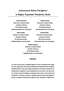
Figure 1: A UA in the Presence of Moving Obstacle To deal with the changing environment, as the new obstacle information becomes available, the parameterized trajectory given by equation 2 may require updates. The updating could be satisfied by a piecewise polynomial parametrization. Let T be the time for a UA to complete its maneuver from the initial configuration q0 to its final configuration qf , and Ts be the sampling period, such that k¯ = T /Ts is an integer. When k = 0, the initial condition is q0 . To k¯ > k > 0, the initial condition is given by qk = (rxk , ryk , rθk ), the terminal condition is always qf . By using the new initial condition, the path planning method described in the previous subsection can be used for real-time replanning as k increases. In the latter part of this paper, all the notations with superscript k or subscript k indicate they are in the k − th sampling period. Figure 1 illustrates a UA moving from q0 to qf , the radius of the UA envelop, r, and the sensing range, Rs are known. At the beginning of the kth sampling period, there is a moving obstacle in the sensing range of the UA, the radius of the obstacle envelop is R with center at (xk , yk ), In this sampling period,its velocity 3
is vok and assumed to be linear and the values for the data is obtained by onboard sensors. The trajectory equation 2 is rewritten as: ry = ak0 + ak1 rx + ak2 rx2 + ak3 rx3 + ak4 rx4
(3)
k k τ )2 + (rx − xk − vo,x τ )2 ≥ (r + R)2 (ry − yk − vo,y
(4)
The obstacle avoidance criterion is:
Where τ = t − (t0 + kTs ) for t ∈ [t0 + kTs , t0 + T ]. According to the results in previous section, [ak0 ak1 ak2 ak3 ]T = (B k )−1 (Y k − Ak ak4 ) where
1 rxk 0 1 Bk = 1 rxf 0 1
(rxk )2 2rxk (rxf )2 2rxf
ryk (rxk )3 k 2 tan(rθk ) 3(rx ) k f 3 , Y = ryf (rx ) f 2 3(rx ) tan(rθf )
(5)
(rxk )4 k 3 , Ak = 4(rfx )4 . (rx ) 4(rxf )3
It is not necessary to consider the collision avoidance criterion for all t ∈ [t0 + kTs , t0 + T ]. Since the collision may only happen when UA’s x (or y) coordinate is within a certain range. Specifically, the potential k k collision range obtained from x coordinate is when rx ∈ [xk + vo,x τ − r − R, xk + vo,x τ + r + R]. From this
condition, a potential collision time interval could be solved as [t∗ , t¯∗ ]. It is only in this time interval that the collision avoidance condition is checked. Substituting 3 and 5 into 4, obtains the following inequality: g2 (rx , k)(ak4 )2 + g1 (rx , k, τ )ak4 + g0 (rx , k, τ )|τ =t−t0 −kTs ≥ 0
(6)
for all t ∈ [t∗ , t¯∗ ]. Where g2 (rx , k) =
[rx4 − h(rx )(B k )−1 Ak ]2
g1 (rx , k, τ ) =
k 2[rx4 − h(rx )(B k )−1 Ak ][h(rx )(B k )−1 Y k − yk − vo,y τ]
g0 (rx , k, τ ) =
k k [h(rx )(B k )−1 Y k − yk − vo,y τ ]2 + (rx − xk − vo,x τ )2 − (r + r)2
h(rx ) =
[1 rx rx2 rx3 ]
Inequality 6 describes the adjustable coefficient ak4 , and as long as the chosen ak4 satisfies this inequality, the obstacle is avoided. For multiple moving obstacles, each obstacle would impose a constraint similar to (6) to ak4 . When ak4 satisfies all the constraints simultaneously, all obstacles are avoided.
4
5
Cooperative Control
5.1
Objectives of Cooperative Control
In general, the control objective for cooperative control is to make the states of a group of dynamical systems converge to same steady state. In the formation fly case, since the position and orientation is the states, the control objective is making the error system converge to zero, thus UAs converge to a formation.
5.2
Cooperative Control Algorithm
Define the transformations φ1 = rx + L cos(rθ ), φ2 = ry + L sin(rθ ), and
·
v1 v2
¸
· =
cos(rθ ) −L sin(rθ ) sin(rθ ) L cos(rθ )
¸·
vr1 vr2
¸
The UA model can be transformed into the single integrator model as follows with the stable internal dynamics φ˙ = v,
(7)
where φ = [φ1 , φ2 ]T and v = [v1 , v2 ]T . A formation is defined in a coordinate frame, which moves with the desired trajectory. Let e1 (t) ∈