We call these flows wavy core annular flow (WCAF). Perfectly ... supervision of Veet Kruka for 12 years from 1970 until the Ten Section facility was closed.
To Appear, Annual Review of Fluid Mechanics, Vol. 29, January 1997.
CORE-ANNULAR FLOWS D.D. Joseph,* R. Bai,* K.P. Chen,† Y.Y. Renardy‡
ABSTRACT This paper gives a brief overview of the issues posed by the science and technology for transporting heavy oils in a sheath of lubricating water. It touches on measures of energy efficiency, industrial experience, fouling, stability, models of levitation and future directions.
INTRODUCTION There is a strong tendency for two immiscible fluids to arrange themselves so that the lowviscosity constituent is in the region of high shear. We can imagine that it may be possible to introduce a beneficial effect in any flow of a very viscous liquid by introducing small amounts of a lubricating fluid. Nature’s gift is evidently such that the lubricating fluid will migrate to the right places so as to do the desired job. This gives rise to a kind of gift of nature in which the lubricated flows are stable, and it opens up very interesting possibilities for technological applications in which one fluid is used to lubricate another. Water-lubricated transport of heavy viscous oils is a technology based on a gift of nature in which the water migrates into the region of high shear at the wall of the pipe where it lubricates the flow. Since the pumping pressures are balanced by wall shear stresses in the water, the lubricated flows require pressures comparable to pumping water alone at the same throughput, independent of the viscosity of the oil (if it is large enough). Hence savings of the order of the oil to water viscosity ratio can be achieved in lubricated flows. Lubricated flow in an oil core is called core annular flow, CAF for short. Typically, waves appear on the surface of the oil core and they appear to be necessary for levitation of the core off the wall when the densities are different and for centering the core * † ‡
Dept. of Aerospace Eng. & Mech., University of Minnesota, Minneapolis, MN 55455 Dept. of Mechanical & Aerospace Eng., Arizona State University, Tempe, AZ 85287 Dept. of Math., Virgina Polytechnic Institute & State University, Blacksburg, VA 24061
1
when the densities are matched. We call these flows wavy core annular flow (WCAF). Perfectly centered core flows (PCAF) of density matched fluids in horizontal pipes and, generally in vertical pipes, are possible but are rarely stable (Joseph & Renardy 1993; Preziosi et al 1989; Chen et al 1990). The science behind the technology of CAF has given rise to a large literature which has been reviewed by Oliemans & Ooms 1986 and more recently by Joseph & Renardy 1993. This literature has many facets which include models for levitation, empirical studies of energy efficiency of different flow types, empirical correlations giving the pressure drop versus mass flux, stability studies and reports of industrial experience.
INDUSTRIAL EXPERIENCE It is best to start this review with industrial experience since the potential of lubricated lines for energy efficient transport of heavy oil gives this interesting subject an even greater urgency. Heavy crudes are very viscous and usually are somewhat lighter than water, though crudes heavier than water are not unusual. Typical crudes might have a viscosity of 1000 poise and a density of 0.99 g/cm3 at 25˚C. Light oils with viscosities less than 5 poise do not give rise to stable lubricated flows unless they are processed into water/oil emulsions and stiffened. Oil companies have had an intermittent interest in the technology of water-lubricated transport of heavy oil since 1904. Isaacs & Speed 1904 in U.S. Patent #759374 were the first to discuss water lubrication of lighter oils which they proposed to stabilize by centripetal acceleration created by rifling the pipe. For stratified flow, Looman 1916 patented a method of conveying oils by passing them over an array of water traps at the bottom of the pipe. An extended history of patents is presented in Joseph & Renardy 1993. The patent history of the subject as it is presently understood starts with the application of Clark & Shapiro 1949 of Socony Vacuum Oil Company who used additives to reduce the density differences between the oil and water and anionic surfactants to reduce emulsification of water into oil. Clifton & Handley 1958 of Shell Development proposed to prevent the emulsification of oil at pumps by removing the water before and inserting the oil after the pumps. In fact, water-in-oil emulsions can be pumped in a sheath of water despite the fact that the viscosity of the emulsion can be orders of magnitude larger than the oil alone. In general, lubricated flows are more effective when the oil is more viscous; the water/oil emulsion is an “effective” thickened oil whose density is closer to water. Kiel 2
1968 of Exxon patented a CAF process for pumping heavy oils and water in oil emulsions, surrounded by water, for fracturing subterranean formations to increase oil and gas production. Ho & Li 1994 of Exxon produced a concentrated water in oil emulsion with 7 to 11 times more water than oil, which they successfully transported in CAF. Syncrude Canada Ltd has undertaken studies of lubricated transport of a bitumen froth which is obtained from processing of oilsands of Alberta for upgrading to Synthetic crude. The oil (bitumen) is extracted from mined oilsands rather than pumped directly from the reservoir. A hot-water extraction process is used to separate bitumen as froth from sand and the average composition of the froth is 60, 30 and 10 weight % bitumen, water and solids, respectively. Internal studies led by Neiman et al 1985 and recent studies at the University of Minnesota have shown that the produced bitumen froth will self lubricate in a pipe flow. Lubricated transport of concentrated oil-in-water emulsions is also an issue. The viscosity of such emulsions can be much smaller than the viscosity of the oil and may be independent of the oil viscosity for large viscosities. This has motivated the consideration of pumping heavy crudes through pipelines as concentrated oil-in-water emulsions. Lamb & Simpson 1973 reports a commercial line in Indonesia which carries 40,000 barrels/day of 70% oil/water emulsion in a 20-inch diameter line, 238 kilometers long. Another commercial lubricated transport of Orimulsion, a coal substitute fuel of 70% oil-in-water produced in Venezuela and marketed by Bitor, can be accomplished naturally since the water for lubrication is already there and will stick to the wall if the surfactant used to stabilize the emulsion and the material of wall construction is suitable (Núñez et al 1996). Probably the most important industrial pipeline to date was the 6-inch (15.2 cm) diameter, 24-mile (38.6 km) long Shell line from the North Midway Sunset Reservoir near Bakersfield, California, to the central facilities at Ten Section. The line was run under the supervision of Veet Kruka for 12 years from 1970 until the Ten Section facility was closed. When lubricated by water at a volume flow rate of 30% of the total, the pressure drop varied between 900 psi and 1,100 psi at a flow rate of 24,000 barrels per day with the larger pressure at a threshold of unacceptability which called for pigging. In the sixth year of operation the fresh water was replaced with water produced at the well site which contained various natural chemicals leached from the reservoir, including sodium metasilicate in minute 0.6 wt.% amounts. After that the pressure drop never varied much from the acceptable 900 psi value; the CAF was stable as long as the flow velocity was at least 3 ft/s. Industrial experience suggests that inertia is necessary for successful CAF. 3
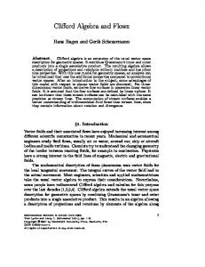
FOULING AND RESTART Even though lubricated flows are hydrodynamically stable, oil can foul the wall. This is an adhesion rather than a hydrodynamic effect and is not taken into account in the equations used to study stability. The hydrodynamic stability of lubricated flow is very robust even when oil wets the wall. A water annulus can lubricate an oil core even in a pipe whose walls are spotted with oil. Sometimes, however, the fouling builds up, leading to rapidly increasing pressure drops even blocking the flow. An example taken from an experiment in which Zuata crude oil (ρ = 0.996 g/cm3, η = 1,150 poise at 25˚C) from the Orinoco belt was pumped through an 8" (20 cm) ID, 1-km pipeline with input fraction of 4% water and superficial oil velocity of 1.5 m/s as shown in Figure 1. The pressure gradient increased monotonically from about 29 psi up to 174 psi due to the gradual fouling of the pipes. If allowed to continue, the Zuata would completely foul and block the pipeline.
200
Pressure (psi)
150
100
50
0 0
10
20
30
40
50
60
70
Elapsed Time (hours)
Figure 1. Fouling of the San Tomé test loop with Zuata crude. Input fraction = 4%, superficial oil velocity = 1.5 m/sec. Pressure losses increase monotonically as the pipeline fouls. High blockage was experienced after 2 1/2 days of operation.
The experiments in Venezuela also showed that oil fouled some places more than others, near pumping stations where the pressure is highest and the holdup and core wave structure are developing and around line irregularities such as unions, bends, flanges and
4
curves. Another major problem is an unexpected shut-down in the line; the oil and water stratify, causing the oil to stick to the pipe wall, making it harder to restart the line. It is desirable to lubricate the oil core with as little water as possible because a small water input alleviates the problem of dewatering. On the other hand, oil is more likely to foul the pipe wall when a small amount of water is used, so it is desirable to suppress fouling for this as well as other reasons. Remedial strategies to prevent fouling naturally alter the adhesive properties of the wall which depend on the solid surface and the oil used. The different strategies that have been tried were discussed by Ribeiro et al 1995 and by Arney et al 1995. The addition of sodium silicate to the water will inhibit fouling of carbon steel pipes. It does so by increasing the negative charge density of the steel surface through the absorption of SiO3−2 ions. But the flowing water constantly washes the silicate ions from the steel pipe walls, so a continuous supply is needed. The continuous addition of sodium m-silicate did not completely suppress the fouling of Maraven’s 54 km San Diego-Budare line by Zuata crude. Sodium m-silicate also helps to make normally hydrophobic quartz glass hydrophilic. Although the effect lasts longer on glass than carbon steel, it does not appear to be permanent. A very substantial increase in the hydrophilicity of quartz can be achieved by hydration in sodium m-silicate and a surface gel may actually form there. Desirable aggregates in mortars of Portland cement are principally quartz or silicates so that these treatments should be studied further. It is well known that mortars of Portland cement form strongly hydrophilic calcium silicate hydrate gels (C-S-H) naturally in curing. The addition of small amounts of sodium msilicate appears to promote the calcium-silicate composition that renders the gel more hydrophilic. The hydrophobic properties of the C-S-H gels are persistent but may slowly degrade due to slow changes in composition when immersed in fresh water. The hydrophilic properties of a degraded gel can be restored by recharging the mortar in a sodium silicate solution. Cement linings may offer a practical solution to the problem of fouling because they not only have good oleophobic properties but are commercially available at prices not greatly in excess of unlined pipes. In the experiments reported by Arney et al. a pilot scale cementlined core-annular flow pipeline using No. 6 fuel oil never fouled in over 1000 hours of operation. Repeated and determined attempts to soil properly hydrated cement-lined pipes with heavy Venezuelan crudes under conditions modeling restart always failed. However,
5
if the pipe is not well hydrated, it will foul; clean up procedures for fouled cement pipes should be developed. Obviously, the restart of a fouled pipe will be easier if the oil does not strongly stick to the pipe wall. The restart is also easier if there is an open channel through which water may flow. Such a channel can be opened by stratification under gravity in a large diameter horizontal line. The flowing water will produce a propagating solitary wave near the pump, which tends to partially block the flow of water in such a way that the high local pressure fingers water between the oil and pipe wall in an unzipping motion which restores core flow as the wave moves forward. The open channel may be closed at places where the pipe goes over a hill since the lighter oil will fill the pipe at high places and make restart more difficult. In small pipes, in which capillarity may dominate gravity, the oil will stratify in slugs separated by water lenses in which water is trapped. A comparison of pipelining in a single large diameter pipe to parallel pipelining in many small pipes is given in Joseph et al 1995.
FLOW TYPES Two-phase flows, liquid-liquid, gas-liquid and liquid-solid flows, can be arranged by dynamics into different configurations called flow types. Various properties of the solutions, like the pressure gradient needed to drive the flow and the area averaged velocity of each phase, depend on the flow type. The two phases of interest here are oil and water. To describe the arrangements of oil and water which occur in experiments, it is useful to define superficial velocities Uo = Qo A ,
Uw = Qw A ,
(1)
where Qo and Qw are the volume flow rates of oil and water and A = π R22 is the crosssectional area of the pipe, and area averaged velocities Uo = Qo Ao ,
Uw = Qw Aw ,
(2)
where Ao = π Ro2 and Aw = π Rw2 are the effective areas and Ro and Rw are effective radii of oil and water in the pipe. The quantities are connected to measured volumes of Vo and Vw of oil in water in a sufficiently large length L of pipe, which could be one wavelength in periodic flow, by
6
Vo = Ao L ,
Vw = Aw L .
(3)
In PCAF, with oil inside, Ro = R1 and Rw2 = R22 − R12 ; the same formulas work for all lubricated pipelines when R1 is the average radius of the core. The holdup ratio of oil to water is defined as h=
Qo Qw Uo = . Vo Vw Uw
(4)
This ratio is a property of the solution or flow type. In the case of an emulsion of small water droplets uniformly dispersed in oil, we could assume that the water moves with the oil so that Uw = Uo , hence h = 1. This does not mean that the flow rates or superficial velocities are equal because, say, only a relatively small amount of water could disperse into small drops. In the case of PCAF, with only a very small water input so that the layer of water outside is thin and a uniform velocity for very viscous oil inside, we get 1 U w = Uo , 2
(5)
hence h =2. In vertical flow with a pressure gradient producing flow of water down against a stationary buoyant slug of oil held in place by gravity, we have h = 0 because Qo = 0 even though the oil fills nearly all of the pipe. Bai et al 1992 found some remarkable holdup results for vertical core flows. For bamboo waves in up-flow, h ≈ 1.39 independent of the flow rates. Though h varies between 0.8 and 1.4 with flow rates of oil and water, h → 1.4 for fast flows Uo Uw > 5 (see Figures 14.3 and 14.4 in Joseph & Renardy 1993). Thus, h = 1.4 is a good value for up-flow and fast down-flows in which buoyancy is not important. In the absence of better knowledge, readers may assume h ≈ 1.4 . The lubricated arrangements of oil in water flow are PCAF, WCAF, slugs of oil in water and drops of oil in water. Well-dispersed drops of oil in water are sometimes called oil-inwater (o/w) emulsions. Very concentrated o/w emulsions can be stabilized by surfactants. Water-in-oil (w/o) emulsions are an oil continuous phase of an “effective” oil which can be lubricated with water. Effective oils of high viscosity can be formed from water in low viscosity oil emulsions (see Ho & Li 1994). When the water content of such w/o emulsions is high, the density of the effective oil will be close to water.
7
We have already alluded to the fact that lubricated arrangements are hydrodynamically stable. However, lubrication may fail to fouling, to stratification under gravity when the density difference is large (and core speeds too low to levitate the core off the wall) and to inversion to w/o emulsions (which can be relubricated as “effective” oils). Failure to stratification at low speeds is characteristic in large diameter pipes in which capillarity is not important. In small pipes, slugs of oil separated by water will stratify in the pipe. A comprehensive classification of flow types for the case of matched density (oil plus additive in water) was given by Charles et al 1961. An extensive classification of horizontal oil-water flows for low viscosity light oils together with two-phase flow model studies can be found in the Ph.D. thesis of José Trallero (Trallero 1995). A classification of flow types in up- and down-flows in vertical pipes can be found in Bai et al 1992. The response of the two-phase flow to applied pressure gradients depends on the flow type. In the engineering literature, the flow types are correlated with prescribed input data in flow charts shown in cartoon form in Figures 2, 3, and 4. These figures delineate regions in the plane of Uo vs. Uw where different types of flow are found. The borders between the flow regions are not clearly defined, but there is a characteristic arrangement in each region of Figures 2 and 3 that show flow types in experiments in the vertical inverted loop used in the experiments of Bai et al 1992. The oil in the vertical flow experiment is lighter than water so that buoyancy and the pressure gradient act in the same sense in upflow, where the core is stretched to produce bamboo waves (Figure 2c) and in the opposite sense in down-flow, where the core is compressed and may buckle in corkscrew waves (Figure 3c). Cartoons of other structures which can be identified with different flow regimes are shown below. For fast flows, buoyancy is relatively less important and the flows in up and down-flow are similar, short steep waves push into the water. Flow charts together with some representative flow types are shown in cartoon form for up-flow, down-flow and horizontal flow of a lighter than water oil.
8
10 water in oil dispersion (e) (d)
Uo (ft/sec)
1.0
bamboo waves (c) slugs
(b)
0.1
bubbles (a) oil in water dispersion 0.01 0.01
0.1
(a)
(b)
Uw (ft/sec)
(c)
1.0
(d)
10
(e)
Figure 2. Cartoons of flow chart and flow types in up-flows in a vertical pipeline (cf. Figure 16.1, Joseph & Renardy 1993).
9
10 water in oil dispersion short bamboo waves (e) 1.0
(d)
(c)
disturbed core annular flow slugs 0.1
(b) bubbles (a) oil in water dispersion
0.01 0.01
1.0
0.1
10
Uw (ft/sec)
(a)
(b)
(c)
(d)
(e)
Figure 3. Cartoons of a flow chart and flow types in down-flow in a vertical pipeline (cf. Figure 16.3, Joseph & Renardy 1993).
10
10 (h) water in oil dispersion 1.0 Uo (ft/sec)
(i)
flying core flow (g)
(f) corkscrew core flow
(d)
slugs 0.1
(c)
bubbles
(e)
(b)
oil in water dispersion
stratified flow
0.01 0.01
(a)
1.0
0.1
10
Uw (ft/sec)
(a)
(e)
(b)
(f)
(c)
(g)
(d)
(h)
(i)
Figure 4. Cartoons of a flow chart and flow types in horizontal flow when the oil is lighter. The flow is from right to left.
11
PRESSURE GRADIENT AND MASS FLUX It is desirable to transport as much oil as possible at a fixed pressure gradient. Joseph et al 1985 solved a variational problem of PCAF in which the flux of oil in a pipe of radius R2 is maximized with respect to the radius of R 1 of the oil core. The flux has a definite maximum when 1 R1 = 2 − m
1
2
For very viscous oils, m is small and R1 = R2
µw . µo
m=
R2 ,
(7)
2.
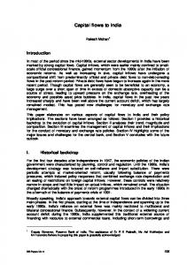
Of course, the pressure gradient depends on the flow type. In Figures 5 and 6, we present plots of the dimensionless pressure gradient θ = ∆p ρw gL , where ∆p L is the pressure drop per unit length versus the input ratio Uw Uo for different values of Uo taken from the vertical flow experiments of Bai et al 1992. The minimum pressure gradients are found for flow types near to PCAF; wavy flows are energy efficient and the input ratio can be controlled to achieve maximum efficiency. The preferred dimensionless representation of pressure gradient vs. mass flux data is in Moody charts of friction factor vs. Reynolds number. The definitions of core flows are required. The problem of finding the definitions that correlate data from all sources on friction factors and holdup ratios was considered by Arney et al 1993. They considered data from 12 different sources and found a good fit of holdup data to the empirical equation
[
]
Hw = Cw 1 + 0.35(1 − Cw )
(8)
where Hw = Vw (Vo + Vw ) and Cw = Qw (Qw + Qo ) are the volume ratio and mass flow ratio. The radius ratio η = R1 R2 = 1 − Hw for an average R 1 can be computed from input data. The value of η is needed in the definitions of the friction factor
λ=
64 + up − flow ± B , ℜ − down − flow
12
(9)
1.0 pressure gradient (feet of water/foot)
(a)
oil in water dispersion
(b) (c)
0.1
bubbles (d) bamboo waves
water in oil dispersion (e)
slugs
0.01
0.001 0.01
1.0
0.1
10
Uw /Uo
pressure gradient (feet of water/foot)
1.0 oil in water dispersion
(a) (b)
short bamboo waves (c) bubbles (d)
0.1
water in oil dispersion
slugs
(e)
0.01 0.01
disturbed core annular flow
1.0
0.1
10
Uw /Uo
Figure 5. (From Bai et al 1992) Dimensionless pressure gradient versus the inverse input ratio for different values of the oil velocity in ft/sec: (a) 0.31 (b) 0.61; (c) 0.91; (d) 1.51; (e) 2.27. (top) represents up-flow and (bottom) represents down-flow.
13
10
1
λ = 64/ ℜ 0.25
λ
λ = 0.316/ ℜ 0.1
0.01
0.001 102
103
104
105
ℜ
106
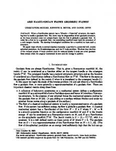
Figure 6. (after Arney et al 1993) Reynolds numbers vs. friction factor λ (see (9)) for all known literature data .
where ℜ=
B=
[
]
2 ρc R2U 1 − η 4 ( m − 1) , µw
( ) [ ρcU [1 + η 4 ( m − 1)]
].
4( ρw − ρo )gR2 1 − η 2 η 2 1 + η 2 ( m − 1) 2
(10)
ρc is the composite density and U = (Uo + Uw ) π R22 is the overall superficial velocity. The data from 12 authors is plotted in the λ– ℜ plane in Figure 6. Most of the data points are in the region of turbulent flow where the Blasius formula λ = 0.316 ℜ1 4 applies. The scatter in the data may be due to fouling of the pipe wall. A model of core-annular flow in which the oil core is a perfect cylinder with generators parallel to the pipe wall, but off center, was studied by Huang & Christodoulou 1994 and Huang & Joseph 1995 in laminar and turbulent flow to assess the effects of eccentricity and
14
volume flow rate ratio on the friction factor and hold-up ratio. For the turbulence analysis, the water was assumed to be turbulent and the core laminar. A standard k-ε model with a low Reynolds number capability was adopted for the turbulence model. The agreement between model predictions, which have no adjustable parameters, and experimental and field data from all sources, was excellent. This result suggests that the major source of drag is turbulence in the water.
EQUATIONS OF MOTION AND DIMENSIONLESS PARAMETERS Oil and water are in region 1 and 2 in a pipe of radius R2 . The fluids are incompressible with densities ρ1, ρ2 and viscosities µ1, µ2 ; div u = 0 where u is the velocity which vanishes at the pipe wall at R2 . The conservation of momentum in regions l= (1, 2) can be expressed as:
ρl [
∂u + u •∇u ] = −∇p + µl∇2 u + ρlg ∂t
(11)
where g is gravity and p is pressure. At each point x(t ) on an oil-water interface F( x(t ), t ) = C with possibly many different constants C for each drop or slug. At these points the velocity is continuous [| u |] ≡ u1 − u2 = 0 and the stress traction is balanced by the surface force
[| − p1 + 2 µ D [u] |] • n = ∇2σ + Hσ n
(12)
where σ is the surface tension; ∇2 σ is the surface gradient for problems of Maragnoni flow when gradients of σ can be induced by temperature or concentration, H is the mean curvature, D [u] is the rate of strain and n = ∇F / | ∇F | is the normal at x(t ) . Since the equations of the interfaces F = C are identities in t, ∂F ∂ t + u • n ∇F = 0 . To complete the mathematical specification of these problems we must specify the length of pipe and inlet and outlet conditions. This specification is enormously complicated even when the pipe is infinitely long, the only case so far studied, because there are so many flows, each of great geometrical complexity. To obtain a more manageable problem attention so far has been mostly confined to wavy flows with a continuous core given by F = r − R( x,θ , t ) = 0 periodic in x and θ with a mean radius R1, taken over x and θ
15
independent of t. A reasonable initial value problem is to prescribe the velocity and position of all points in the pipe initially and the volume flow rates Q1 and Q2 at all subsequent times, together with periodic, boundary and interface conditions mentioned above. To get a constant R1, Q1 and Q2 should be constant. Dimensionless parameters for these problems cannot be uniquely defined and are chosen artfully according to the purposes of the calculation (see Joseph and Renardy [1993] for 2 examples). In one choice, we choose a scale length R2 , a scale velocity W = Q1 / π R2 , which is the superficial velocity of oil, a scale time T = R2 / W , and a scale pressure ρ2W 2 . After substituting these scales into the equations one finds the following dimensionless groups in the dimensionless equations following from (11) and (12) while all other dimensionless variables are form invariant, without these seven groups:
η=
R1 ρ1 µ1 , , . are radius, density, and viscosity ratios, R2 ρ2 µ2
Re =
WR2 ρ2 µ2
is the Reynolds number for the water,
f =
g R2
S=
σ J = is a surface tension parameter, 2 ρ2W R2 Re 2
W2
is a Froude number,
Q1 is the input ratio. Q2 Preziosi, Chen and Joseph [1989] argued that J=
ρ2 R2σ µ22
(13)
is a better surface tension parameter than S because it is independent of velocity. When the density is matched ρ1 = ρ2 , the gravity term may be removed by a hydrostatic pressure, reducing the number of dimensionless parameters to five. In the case of a rigid, but deformable core considered in the direct simulation by Bai et al. [1995],
16
µ1 / µ2 = µw / µo = 0 and only four parameters, R , η, J
and h
are required where the hold up h, given by (4) may be obtained from R = (1 − η ) Re = ρ2 ( R2 − R1 ) W µ2
Q1 and η and Q2 (14)
STABILITY Flow types are determined by stability. As the flow parameters change, some types of flow lose and others gain stability. The theory of stability is the natural way to analyze the transition between flow types. Unfortunately, because general stability analysis is difficult, most of the studies are confined to PCAF for which the linear stability analysis may be reduced by normal modes to eigenvalue problems for ordinary differential equations. Perfect core-annual flow is only possible for vertical pipes and for horizontal pipes when the two fluids have the same density. For this idealized flow, all measures of flow efficiencies, such as hold-up ratios, maximum volumetric flow rate for oil (the core fluid) for a prescribed pressure gradient, and the minimum pressure gradient for delivering oil at a required flow rate can be computed (Churchill 1988). The stability of PCAF is thus of interest to lubricated pipelining, but other more difficult analysis of wavy and eccentric flow needs to be done.
Linear Theories A thorough review of stability studies prior to 1992 together with mathematical details can be found in Joseph & Renardy 1993. Studies of linear stability of PCAF were done by Hickox 1971, Joseph et al 1985, Preziosi et al 1989, Hu & Joseph 1989, Smith 1989, Chen et al 1990, Hu et al 1990, Bai et al 1992, Miesen et al 1992, Georgiou et al 1992, Boomkamp & Miesen 1992, Lin & Lian 1993, and Hu and Patankar 1995. These studies have shown that only the lubricated flow can be stable; PCAF with water inside and oil outside is always unstable. On the other hand, for some operating conditions the lubricating PCAF with the less viscous fluid (water) outside can be stable to both axisymmetric and non-axisymmetric disturbances. In general, only thin lubricating layers are stable, but even in this case the stability depends on flow conditions. If the flow is 17
slow, capillary instability will be induced by interfacial tension. Inertia has a stabilizing effect (Chen & Joseph 1991) and the capillary instability can be completely stabilized by increasing the Reynolds number (Preziosi et al 1989). Further increases in the Reynolds number results in an instability due to interfacial friction, proportional to the viscosity difference. This instability leads to a wavy core flow (WCAF), which can be stable, and in fact is the generic form of core flow in lubricated lines. The parameter range for which PCAF is stable is very small. The linear theory of stability of PCAF is an effective tool to study the transitions between flow types when PCAF is unstable. As the parameters are varied, the growth rates associated with different eigenfunctions may change their order and the change corresponds to a change in the mode of instability seen in experiments as a change in flow type. The linear theory of stability also gives information about the mechanisms which induce instability and the flow types which are associated with these mechanisms. Particularly useful is the evaluation of the global balance of energy of the small disturbance with the largest growth rate. This energy analysis (Hu & Joseph 1989) leads to the identification of three mechanisms of instability: interfacial tension, interfacial friction, and Reynolds stresses, which are thoroughly discussed in Joseph & Renardy 1993. Observed flow patterns correlate very well with the dominant contribution from the energy budget. The energy budget is a powerful diagnostic tool for the analysis of flow types and transition in core-annular flows in pipes. The effect of eccentricity on core-annular flow with matched densities is analyzed by Huang & Joseph 1995. When gravity is absent, an eccentric core flow with a circular interface is an unidirectional-flow solution to the governing equations under a constant pressure-gradient. The position of the center of the core is indeterminate so that there is a family of these eccentric core flows. It is found that an eccentric flow is stable when the corresponding PCAF is stable, and that the linear-stability theory does not select a stable center for core-annular flow in the density-matched case. This suggests that configurations observed in practice are selected by nonlinear mechanisms. Furthermore, it is found that the most amplified wave changes from a varicose type to a sinuous type as the eccentricity is increased. This may offer an explanation to the formation of the cork-screw waves observed in the experiments of Bai et al 1992. In these experiments, an inverse U-shaped pipe is used and the cork-screw waves are observed in the downward flow. It is very likely that eccentricity is introduced into the core when the fluids make the U-turn, and this 18
eccentricity leads to the formation of the cork-screw waves which are sinuous. An alternative explanation to the formation of cork-screw waves is given by Hu & Patankar 1995, who found that the most amplified mode in a vertical PCAF could be sinuous when the oil core is very thin.
Nonlinear Theories Nonlinear stability theories describe dynamics close to PCAF in which some effects of non-linearity are retained. Some flows which perturb stable PCAF near the threshold of linear instability can be shown to satisfy Ginzburg-Landau equations. Other nonlinear theories are based on the assumption that the waves are long relative to some preassigned scale of length. The assumptions made by long wave theories may not be realized in the realized fluid dynamics and the question of validity, separate from analysis, needs to be addressed (see Chen & Joseph 1991, Chen & Joseph 1992 and Joseph & Renardy 1993). There are regions of parameter space in which perfect core-annular flow is possible and there is a threshold for instability, where it can lose stability to waves generated by interfacial friction, or to capillary waves. The marginally stable eigenvalue at criticality is purely imaginary, and a Ginzburg-Landau equation can be derived for this Hopf bifurcation. The derivation of the equation near criticality, using the techniques of multiple scales, or a center manifold theorem, is well known. Slow spatial and time scales are introduced appropriately for a wave packet centered at the nose of the neutral curve, and the long time behavior of this wave train is examined in the frame moving with its group velocity. This theory applies to small-amplitude waves which modulate a monochromatic wave of the critical wavelength. There is also interest to see what kinds of effects may be described by solutions lying in the full solution set of Ginzburg-Landau equations. The formation of solutions and chaos are two such effects which have been examined in a qualitative way (see references in Kerchman 1995). The numerical value of the Landau coefficient in the Ginzburg-Landau equation depends on the specific flow conditions, such as whether the volume flux is kept fixed or the pressure gradient fixed, and on assumptions made in the calculation of the second-order correction to the mean flow (Renardy 1989).
19
The nature of the bifurcation of core-annular flows is determined by the real part of the Landau constants. If this is positive, the bifurcation is supercritical and a finite amplitude stable wavy flow exists. Thus, a robust form of lubricated pipelining with thin lubricating films is expected when the bifurcations are supercritical, but nonlinear failures may occur when the bifurcations are subcritical. On the other hand, there are cases for which increasing the thickness of the lubricating layer can change subcritical to supercritical bifurcation. Details of the explicit coefficients for axisymmetric disturbances to coreannular flow is given in Chen & Joseph 1991 (see all Chapter VIII of Joseph & Renardy 1993). A sideband instability of the flow can lead to growth of the long wave mode, and the excitation of 3D disturbances (Renardy & Renardy 1993) There are many regions of parameter space in which perfect core-annular flow is not achieved, and the Ginzburg-Landau type analysis does not apply. At least two other types of nonlinear amplitude equations can be obtained for core-annular flow when the wavelength is long. The first is where it is long compared with both the core radius and the annulus thickness. This type of approach was pioneered by Benney 1966. For interfacial instabilities, long-wave theories have been developed (Atherton & Homsy 1976, Williams & Davis 1982, Hooper & Grimshaw 1985) leading to the Kuramoto-Sivashinsky equation. The linear part of this amplitude equation is exact in the sense that the linear dispersion relation reduces to that of the full problem in the same limit. The linear mechanism of shear stabilization or destabilization is fully preserved in this amplitude equation, but the dynamics is restricted to the longest waves which are usually not the most strongly amplified. In a second approach taken by Frenkel 1988 and Papageorgiou et al 1990, the wavelength is required to be long only compared with the annulus thickness and wavelengths of the order of the core radius are allowed. Other assumptions on material and flow parameters are required for validity and the contributions of inertia in the annulus is neglected. Shear stabilization arises from the inertia of the core. Inertia in the annulus would induce wave number multiplication and shorter and shorter waves. Theories of this type might apply to situations in which the most amplified mode from linear theory is very long; however, the linearization of this long-wave theory does not coincide with the full linearized theory. The situation with oil in the annulus has been modeled by a long-wave equation based on lubrication theory (Kerchman 1995). Effects such as rotation and background oscillations have also been investigated with lubrication theory. The nonlinear evolution of core20
annular flow within a rotating pipe has been considered by Coward & Hall 1993. The flow is found to be unstable to non-axisymmetric disturbances, which develop into finite amplitude traveling waves in both axial and azimuthal directions. Coward et al 1995 derived a 3D generalization of Kuramoto-Sivashinsky equation for core-annular flow where the pressure gradient is modulated by time harmonic oscillations. They examine the effect of the background oscillations on steady states of KS equation, time-periodic states, chaotic states, traveling wave solutions and traveling nonlinear dispersive states. Oscillatory forcing such as this can be used as a dynamic stabilization or destablization mechanism (Coward & Papageorgiou 1994). Nonlinear theories of the type mentioned here have not yet given rise to practically useful results and the study of validity should be put before the further development of these lines of study.
LEVITATION OF CORE FLOWS A surprising property of core flow is that the flow in a horizontal line will lubricate with the core levitated off the wall even if the core is lighter or heavier than the lubricating water. This levitation could not take place without a hydrodynamic lifting action due to waves sculpted on the core surface. In the case of very viscous liquids, the waves are basically standing waves which are convected with the core as it moves downstream. This picture suggests a lubrication mechanism for the levitation of the core analogous to mechanisms which levitate loaded slider bearings at low Reynolds numbers. Ooms et al 1984 and Oliemans and Ooms 1986 gave a semi-empirical model of this type and showed that it generated buoyant forces proportional to the first power of the velocity to balance gravity. In this theory, the shape of the wave must be given as empirical input. Consider water-lubricated pipelining of crude oil. The oil rises up against the pipe wall because it is lighter than the water. It continues to flow because it is lubricated by waves. However, the conventional mechanisms of lubrication cannot work. The saw tooth waves shown in Figure 7 are like an array of slipper bearings and the stationary oil core is pushed off the top wall by lubrication forces. If c were reversed, the core would be sucked into the wall, so the slipper bearing picture is obligatory if you want levitation.
21
CORE
ANNULUS
PIPE WALL
L
R2
x
c x=L
x=0
Figure 7. The core is at rest and the pipe wall moves to the left. Obviously the saw tooth waves are unstable since the pressure is highest just where the gap is smallest, so the wave must steepen where it was gentle, and smooth where it was sharp. This leads us to the cartoon in Figure 8. To get a lift from this kind of wave it appears that we need inertia, as in flying. Liu’s [1982] formula for capsule lift-off in a pipeline in which the critical lift off velocity is proportional to the square root of gravity times the density difference is an inertial criterion. Industrial experience also suggests an inertial criterion, since CAF in the Shell line could be maintained only when the velocity was greater that 3 ft/s; at lower velocities the drag was much greater.
Figure 8. (After Feng et al 1995) (top) The interface resembles a slipper bearing with the gentle slope propagating into the water. (middle) The high pressure at the front of the wave crest steepens the interface and the low pressure at the back makes the interface less steep. (bottom) The pressure distribution in the trough drives one eddy in each trough.
22
DIRECT NUMERICAL SIMULATION Analysis of problems of levitation, transitions between flow types, pressure gradients and hold-up ratios will ultimately be carried out by direct numerical simulation. Bai et al 1995 did a direct simulation of steady axisymmetric, axially periodic CAF, assuming that the core viscosity was so large that secondary motions could be neglected in the core. They found that wave shapes with steep fronts like those shown in Figure 8 always arise from the simulation. A selection of such shapes is shown in Figure 9. The wave front steepens as the speed increases. The wave shapes are in good agreement with the shapes of bamboo waves in up-flows studied by Bai et al 1992. A new and important feature revealed by the simulation is that long waves do not arise when the gap size tends to zero as is usually assumed in long wave theories. As the gap size decreases, η → 1, the wavelength L (η) decreases linearly with η as shown in Figure 10. This means that the wave shape hardly changes and a steep wave will stay steep in this limit. It is the first solution ever to show how “sharkskin” waves arise as a natural consequence of the dynamics of lubricated flows without the special assumptions sometimes made in the rheology literature to explain such waves shapes in extrudate flows. Bai et al 1995 found a threshold Reynolds number corresponding to a change in the sign of the pressure force (the area under the pressure curve) on the core from suction at Reynolds numbers below the threshold, as in the reversed slipper bearing in which the slipper is sucked to the wall, to compression for Reynolds numbers greater than the threshold, as in flying core flow in which the core can be pushed off the wall by pressure forces (see Figure 11). The existence of this threshold does not prove that inertia is required for levitation of core flows in which the density is not matched and the centering of flows of matched density because in the axisymmetric case studied by Bai et al 1995, the pressure forces are always balanced by an equal and opposite force an the other side of the core.
23
A 0
1
2
3
4
E 0
5
1
2
3
4
5
F
B 0
1
2
3
4
0
5
1
2
3
4
5
G
C 0
1
2
3
4
0
5
1
2
3
4
5
H
D 0
1
2
3
4
0
5
1
2
3
4
I
0
1
2
3
4
5
Figure 9. (After Bai et al 1995) Selected wave shapes for water lubricated axisymmetric flow of oil and water with the same density ρ = 1.0 g/cm3, µ0 = 0.01 poise and σ = 26 dyne/cm for oil and water. The core is stationary and the wall moves to the right. The pipe diameter is R 2 = 1.0 cm. Qo and Qw are in cm3/sec. The data for each frame is given as a triplet of prescribed dimensional values (R1, Qo, Qw) and as a triplet of prescribed dimensionless values [η, h, R ] where η = R1 R2 , h is the holdup ratio and Reynolds number R is defined by (14). The dimensionless surface tension J = 13 × 104 defined in (13) is for all frames. The data for each dimensional and dimensionless triplet is A (0.4, 12.6, 5.05), [0.8, 1.4, 250]; B (0.4, 22.6, 9.09 ), [0.8, 1.4, 450 ]; C (0.4, 37.7, 15.2), [0.8, 1.4, 750]; D (0.43, 34.9, 8.8), [0.86, 1.4, 420]; E (0.43, 43.6, 11), [0.86, 1.4, 525]; F (0.43, 69.7, 17.5), [0.86, 1.4, 840]; G (0.39, 26.1, 12), [0.78, 1.4, 600]; H (0.41, 35.2, 12.3), [0.82, 1.4, 600]; I (0.425, 45.4, 12.5), [0.85, 1.4, 600]. Frames A through F show that the wave front steepens and the wavelength decreases for increasing R . Frames G through I show how the wavelength shrinks as the thickness of the water layer decreases. The wave shape does not change much as η is increased for given values of h and R because the wavelength and amplitude both decrease. This gives rise to a nearly “self similar” wave shape leading to “sharkskin” as η → 1 (cf. Figure 10)
24
5
2.5 105
2.6 G a
2.32
b
1.8 105 _ 2.04 L
H
β∗
1.76
1.2 105 I
1.48 1.2 0.76
0.78
0.8
0.82 η
0.84
0.86
5.0 104 0.88
Figure 10. (After Bai et al 1995) Curve a represents the wavelength L (η) ≈ 13.463 − 14.087η for [R R , h, J] = [600, 1.4, 13 × 104]; Curve b represents the pressure gradient β * vs. η under the same conditions. The wave shapes for the points G, H, and I are shown in Figure 9. Curve a extrapolates to zero L with a finite η. We could not get convergent results for η very close to 1. The extrapolation suggests a limiting zero value of wavelength and amplitude leading to “sharkskin.”
25
8 10 5
5 10 5
p*
R =750 3 10
5
250 0 10 0 -3 10 5 0
0.2
0.4 _ _ 0.6 z/L
0.8
1
Figure 11. (After Bai et al 1995) Pressure distributions on the interface for R = 0, 10, 250, 750 when [η, h, J] = [0.8, 1.4, 13 × 104]. The pressure force, the area under the pressure curve, is negative for R = 0, 10 and is positive for the larger values. The greatest pressure is at the forward points of stagnation.
FUTURE DIRECTIONS Looking forward, the main scientific issue is the role of inertia in levitation and the main technology issue is the remediation of fouling. Experiments and numerical simulations suggest that inertia is required to levitate cores when the density is not matched and to center them when they are. This issue should be resolved by further simulation in which the assumptions of axisymmetry and the rigid core are relaxed and the effects of gravity on horizontal core flows is fully considered.
26
ACKNOWLEDGMENT This work was supported primarily by the DOE, Department of Basic Energy Science (O. Manley, monitor), by the NSF, the ARO and the Minnesota Supercomputer Institute. The work of K.P. Chen was supported by the NSF and Xerox. The work of Y. Renardy was supported by the NSF under grant NSF-CTS 9307238 and by the ONR under grant N00014-92-J-1664.
REFERENCES Atherton RW, Homsy GM. 1976. On the derivation of evolution equations for interfacial waves. Chem Engng Communication. 2:57-77 Arney MS, Bai R, Guevara E, Joseph DD, Liu K. 1993. Friction factor and holdup studies for lubricated pipelining. Int. J. Mult. Flow. 19(6):1061-1076 Arney MS, Ribeiro GS, Guevara E, Bai R, Joseph DD. 1995. Cement lined pipes for water lubricated transport of heavy oil. Int. J. Mltiphase Flow. (In press) Bai R, Chen K, Joseph DD. 1992. Lubricated pipelining: Stability of core-annular flow. Part 5: Experiments and comparison with theory. J. Fluid Mech. 240:97-142 Bai R, Kelkar K, Joseph DD. 1995. Direct simulation of interfacial waves in a high viscosity ratio and axisymmetric core annular flow. Supercomp. Inst. Res. Rep. #UMSI 95/107. University of Minnesota Benney DJ. 1966. Long wave in liquid film. J. Math. Phys. 45:150-155 Boomkamp PAM, Miesen RHM. 1992. Nonaxisymmetric waves in core-annular flow with a small viscosity ratio. Phys. Fluids. A4(8):1627-36 Charles ME. 1963. The pipeline flow of capsules. Part 2: Theoretical analysis of the concentric flow of cylindrical forms. Can. J. Chem. Engng. 46 Charles ME, Govier GW, Hodgson GW. 1961. The horizontal pipeline flow of equal density of oil-water mixtures. Can. J. Chem. Engng. 39:17-36 Chen K, Bai R, Joseph DD. 1990. Lubricated pipelining. Part 3. Stability of coreannular flow in vertical pipes. J. Fluid Mech. 214:251-286
27
Chen K, Joseph DD. 1991. Lubricated pipelining: Stability of core-annular flow. Part 4. Ginzburg-Landau equations. J. Fluid Mech. 227:226-260 Chen K, Joseph DD. 1992. Long wave and lubrication theories for core-annular flow. Phys. Fluids A. 3(11):2672-79 Churchill SW. 1988. Viscous Flows: The Practical Use of Theory. Massachusetts: Butterworth Publishers.
Stoneham,
Clark AF, Shapiro A. 1949. U.S. Patent No. 2,533,878 Clifton EG, Handley LR. 1958. U.S. Patent No. 2,821,205 Coward A. Hall P. 1993. On the nonlinear interfacial instability of rotating core-annular flows. Theor. Comp. Fluid Dyn. 5:269-289 Coward A., Papageorgiou DT. 1994. Stability of oscillatory two-phase Couette flows. IMA J. Appl. Math. 53:75-93 Coward A., Papageorgiou DT, Smyrlis YS. 1995. Nonlinear stability of oscillatory coreannular flow: S generalized Kuramoto-Sivashinsky equation with time-periodic coefficient. Z. Angew. Math. Phys. 46:1-39 Feng J, Huang PY, Joseph DD. 1995. Dynamic simulation of the motion of capsules in pipelines. J. Fluid Mech. 286: 201-227 Frenkel AL. 1988. Nonlinear saturation of core-annular flow instabilities. Proc. Symp. Energy Eng. Sci., 6th, Argone National Laboratory Georgiou E, Maldarelli C, Papageorgiou DT, Rumschitzki DS. 1992. An asymptotic theory for the linar stability of a core-annular flow in the thin annulus limit. J. Fluid Mech. 243:653-677 Hasson D, Mann U, Nir A. 1970. Annular flow of two immiscible liquids. I. Mechanisms. Can. J. Chem. Engng. 48:514-520 Hickox CE. 1971. Instability due to viscosity and density stratification in axisymmetric pipe flow. Phys. Fluids. 14:251-262 Ho WS, Li NN. 1994. Core-annular flow of liquid membrane emulsion. AIChE Journal. 40(12):1961-68 Hooper AP, Grimshaw R. 1985. Nonlinear instability at the interface between two viscous fluids. Phys. Fluids. 28:3 28
Hu HH, Joseph DD. 1989. Lubricated pipelining: stability of core-annular flow. Part 2. J. Fluid Mech. 205:359-396 Hu HH, Lundgren TS, Joseph DD. 1990. Stability of core-annular flow with a small viscosity ratio. Physics. Fluids A. 2:1945-1954 Hu HH, Patankar N. 1995. Non-axisymmetric instability of core-annular flow. J. Fluid Mech. 290:213-234 Huang A, Joseph DD. 1995. Stability of eccentric core annular flow. J. Fluid Mech. 282:233-45 Huang A, Christodoulou C. 1994. Friction factor and holdup studies for lubricated pipelining. Part II: Laminar and k-ε models of eccentric core flow. Intl. J. of Mult. Flow. 20(3):481-91 Isaacs JD, Speed JB. 1904. U.S. Patent No. 759,374 Joseph DD, Renardy YY. 1993. Fundamentals of Two-Fluid Dynamics. New York: Springer-Verlag Joseph DD, Hu H, Bai R, Liao TY, Huang A. 1995. Parallel pipelining. J. Fluids Eng.. 117:446-449 Joseph DD, Renardy Y, Renardy M. 1985. Instability of the flow of immiscible liquids with different viscosities in a pipe. J. Fluid Mech. 141:309-17 Kerchman V. 1995. Strongly nonlinear interfacial dynamics in core-annular flows. J . Fluid Mech. 290:131-166 Keil OM. 1968. U.S. Patent 3,378,047 Lamb MJ, Simpson WC. 1973. Proc. World Petroleum Cong., 6th, Frankfurt, pp. 2333 Lin SP, Lian ZW. 1993. Absolute and convective instability of a viscous liquid jet surrounded by a viscous gas in a vetical pipe. Phys. Fluids A. 5(3):771-773 Liu H. 1982. A theory of capsule lift-off in pipeline. J. Pipelines. 2:23-33 Looman MD. 1916. U.S. Patent No. 1,192,438 Miesen R, Beijnon G, Duijvestijn PEM, Oliemans RVA, Verheggen T. 1992. Interfacial waves in core-annular flow. J. Fluid Mech. 238:97-117 29
Neiman O. 1986. Froth pipelining tests. Syncrude Canada Research and Development Progress Report. 15(1):373-407 Núñez GA, Briceño M, Mata C, Rivas H, Joseph DD. 1996. Flow characteristics of concentrated emulsions of very viscous oil in water. J. Rheol. In press Oliemans RVA, Ooms G. 1986. Core-annular flow of oil and water through a pipeline. Multiphase Science and Technology. ed. GF Hewitt, JM Delhaye, N Zuber, Vol. 2, Hemisphere Publishing Corporation Ooms G, Segal A, Van der Wees AJ, Meerhoff R, Oliemans RVA. 1984. A theoretical model for core-annular flow of a very viscous oil core and a water annulus through a horizontal pipe. Int. J. Mult. Flow. 10: 41-60 Papageorgiou DT, Maldarelli C. Rumschitzki DC. 1990. Nonlinear interfacial stability of core annular film flows. Phys Fluids A. 2:340 Preziosi L, Chen K, Joseph DD. 1989. Lubricated pipelining: stability of core-annular flow. J. Fluid Mech. 201:323-56 Renardy M, Renardy Y. 1993. Derivation of amplitude equations and the analysis of sideband instability in two-layer flows. Phys. Fluids A. 5:2738-2762 Ribeiro GS, Rivero M, Arney MS, Hall TJ, Joseph DD. 1995. On the adhesion of crude oil to wet ceramics. Can. J. of Chem. Eng. Submitted Smith MK. 1989. The axisymmetric long-wave instability of concentric two-phase pipe flow. Phys. Fluids A. 1(3):494-506 Trallero JL. 1995. Oil-water flow patterns in horizontal pipes. Ph.D. thesis. Univ. Tulsa Williams MB, Davis SH. 1982. Nonlinear theory of film rupture. J. Coll. Interface Sci. 90:220-228
30