wireless standards: IEEE 802.11a [3], 802.11b [3], and 802.11g [3]. The differ- ent standards ... on the distance between two nodes, the transmission rate of a IEEE 802.11b link can be either ...... A. Raniwala and T. Chiueh, Architecture and Algorithms for an IEEE 802.11-Based Multi-. Channel ... 05/Wireless Webcast.ppt. 15.
Cost-Aware Route Selection in Wireless Mesh Networks Junmo Yang1 , Kazuya Sakai2 , Bonam Kim1 , Hiromi Okada2 , and Min-Te Sun1 1
Department of Computer Science and Software Engineering, Auburn University, Auburn, Alabama 36849–5347 Email: {yangjun, kimbona, sunmint}@eng.auburn.edu 2 Department of Electronics Engineering Kansai University, 3-3-35 Yamate-cho, Suita, Osaka, Japan 564-8680 Email: {sakai,okada}@jnet.densi.kansai-u.ac.jp
Abstract. Wireless mesh networks have emerged to be one of the promising applications of ad hoc networks. The idea of installing multiple radio interfaces at each mesh router allows a mesh network to better utilize the available wireless bandwidth, but at the same time complicates the issue of route selection. In this paper, we propose a novel metric that measures the bandwidth and cost ratio of each route. Based on this metric, a Cost-Aware Route Selection (CARS) scheme is proposed to improve the overall throughput of a mesh network. The simulation results confirm that our scheme is able to better utilize the limited wireless resource and improves the overall network throughput by more than 95% with different types of traffic and communication patterns when it is compared against the past route selection schemes.
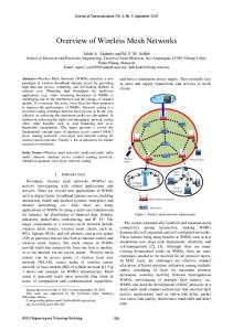
1 Introduction Wireless Mesh Networks (WMNs) have emerged as one of the most promising applications of ad hoc networks. By connecting inexpensive mesh routers with multiple radios wirelessly, WMNs can quickly provide broadband networking infrastructure for large business enterprizes and bring Internet access to residence in rural areas. An example of WMNs is depicted in Figure 1. To take full advantage of WMNs, many research issues, such as backbone construction, cross-layer design, multi-channel MAC, and fault tolerance [1], are yet to be addressed. Among them, routing is perhaps one of the most important topics. At first glance, since WMNs are considered as a special type of ad hoc network, it seems appropriate to use one of the routing protocols originally developed for ad hoc networks [2] for WMNs. However, such an approach overlooks the following three key differences between research in WMNs and traditional ad hoc networks, and is thus likely to result in poor performance. – Node classification - Traditional ad hoc networks are formed by nodes that are commonly assumed to be homogeneous in terms of the hardware/software configuration and degree of mobility. In contrast, wireless mesh networks are composed of two distinct types of nodes - mesh routers and mesh clients. Mesh routers, similar to conventional wireless access points, are generally assumed to be built using inexpensive parts, to be stationary, and to be connected to an external power supply.
2
Notice that most mesh routers are not connected directly to the wired backbone. If a mesh router is connected to the wired backbone, we referred it as the gateway or gateway mesh router in particular. The mesh clients, such as laptops and handheld PDAs with wireless LAN [3] capability, run on their own batteries and move at moderate speed. – Multiple antennas - To increase the capability of WMNs, mesh routers can be equipped with multiple radio interfaces. Each interface can adopt one of the three wireless standards: IEEE 802.11a [3], 802.11b [3], and 802.11g [3]. The different standards present distinct by different physical characteristics, particularly with regard to their radio spectrum, transmission rate, and transmission radius. This immediately presents two challenges for the protocol design. First, the topology of WMNs is no longer a simple graph. Depending on which radio interfaces are available, a mesh router can have several different sets of neighbors. Second, the channels used by different radio interfaces can interfere with each other if the portion of the radio spectrum used by these interfaces overlap with each other. – Adaptive transmission rate - In most research on ad hoc networks, the unit disk model is used [4, 5]. In this model, the transmission rate between two nodes within a predefined transmission range is assumed to be a constant. However, it is known that the transmission rate between two wireless LAN entities can automatically step down if the quality of the link between them degrades. For instance, depending on the distance between two nodes, the transmission rate of a IEEE 802.11b link can be either 11Mbps(0m - 50m), 5.5Mbps(51m - 62m), 2Mbps(62m - 68m), or 1Mbps(68m - 85m) [6].
Fig. 1. An Example of Wireless Mesh Network
These differences further complicate the issue of routing in WMNs. In [7], it was shown that finding the optimal route in a multi-radio WMN is NP-hard. As the first step toward solving this problem, most previous proposals [7–11] suggested different metrics that can be used to help identify the best one out of a set of candidate routes. It is expected that by using these metrics for route selection, the overall throughput of the mesh network can be improved.
3
In this paper, we propose a novel route selection scheme is proposed, namely CostAware Route Selection (CARS), for WMNs. Unlike the past route selection schemes, which are primarily based on the quality of links in a route, the new scheme takes the interference cost and traffic aggregation into consideration. By selecting the route with the best bandwidth and cost ratio from a set of candidates, the limited wireless resources (i.e., the available channels for mesh routers) can be better utilized. This will automatically lead to better overall network throughput. The simulation results show that the proposed CARS scheme significantly improves the overall network throughput by more than 150% in the case of burst traffic and the number of connections by more than 95% in the case of constant bit rate traffic. The remainder of this paper is organized as follows. In Section 2 we review the existing route metrics and route selection schemes for WMNs are required. The proposed route metric and scheme are described in Section 3 and the simulation results and analysis are provided in Section 4. Finally, the chapter concludes by summarizing the research and pointing out the future research directions in Section 5.
2 Survey of Existing Route Selection Schemes in WMNs Routing is one of the most fundamental issues in WMNs. In the past, several metrics were proposed for multi-hop wireless networks in order to measure the quality of a route. In [10], the Expected Transmission Count (ETX), which is based on link layer frame loss rates, was used to locate a path with higher throughput in a multi-hop wireless network. However, ETX does not take into account the bandwidth of links in a path. In addition, ETX does not give preference to channel diversity. In [12], a link quality source routing (LQSR) protocol was proposed which selects a route according to a specified link quality metric. LQSR is an extension of the dynamic source routing protocol [13]. In [12], three different link quality metrics: ETX, perhop round-trip time, and per-hop packet pair, were evaluated and compared, along with LQSR. However, LQSR was designed primarily for nodes with a single radio interface. In [11], the authors promoted the uses of multiple radio interfaces at each mesh router for the improvement of network capacity. Since then, most research on WMNs has adopted this idea. However, while such configurations enable a mesh router to simultaneously transmit and receive packets, it also complicates the selection of routes. It has been shown that finding the optimal route for a given source-destination pair with the best radio and channel in a multi-radio WMN is an NP-hard problem [7]. In [11], a multi-radio LQSR (MR-LQSR) was proposed for mesh routers with multiple radio interfaces. MR-LQSR incorporates several performance metrics. The Expected Transmission Time (ETT), which is essentially the expected time to transmit a packet of a certain size over a link, is introduced to measure the quality of a link. ETT accounts for both packet loss rate and link bandwidth. The Weighted Cumulative Expected Transmission Time (WCETT) is used to measure the quality of a path. WCETT is a combination of the Summation of ETT (SETT) and Bottleneck Group ETT (BGETT), which is the sum of expected transmission time of a bottleneck channel. WCETT takes into account both link quality metric and the minimum hop-count. Depending on the parameter set for SETT and BG-ETT in WCETT, MR-LQSR generally achieves a
4
good tradeoff between delay and throughput. However, MR-LQSR does not consider interference, as the authors assumed that all the radio interfaces on each mesh router are tuned to non-interfering channels. In reality, the number of available channels is limited, so when multiple traffic flows are running on the network the impact of interference should not be overlooked. In [8], a centralized channel assignment and routing algorithm were proposed. The proposed heuristic improves the aggregate throughput of WMNs and balance loads among gateways. For the channel assignment algorithm, load balancing is the first criterion assessed. The routing algorithm used both shortest path routing and randomized routing. In [7], in order to solve a joint channel assignment and routing problem, a traffic flow based channel assignment was proposed to maximize the bandwidth allocated to each traffic aggregation point, subject to the fairness constraint. Unlike the heuristic approach in [7, 8] took into account the interference constraints at each mesh router in the formulation of the joint channel assignment and routing. As a result, the proposed algorithm was able to increase overall throughput. The authors in [7–9] do not consider the use of scheduling in the event of multiple links being assigned to the same channel. In their algorithms, the mesh routers may need to buffer data packets, introducing extra hardware requirements for mesh routers. Moreover, these algorithms do not consider some of the physical characteristics inherent in the IEEE 802.11 standards, such as an adaptive transmission rate and the existence of multiple neighboring sets for a multi-radio mesh router due to the different transmission ranges of the radios.
3 Cost-Aware Route Selection 3.1 Motivation Prior studies [8, 11] have pointed out the shortcomings of the shortest-path routing approach in WMNs. As a result, most of the proposed route selection schemes for WMNs such as [10, 11] are instead based on the quality of links in a route. While these schemes favor routes with higher throughput, they do not take into account the cost of a route. As a result, in cases where multiple active connections are present, these schemes do not scale up well and tend to produce lower overall throughput in multi-radio WMNs. Figure 2 shows 5 candidate routes between source S and destination D. The values of various metrics for these candidate routes, including the shortest-path, SETT, and BG-ETT, are presented in Table 1. As can be seen, the shortest-path will select path 2 or 4, since these two routes consist of only 3 hops; SETT will favor path 4 because it has the lowest value of SETT among all routes (In general, SETT tends to favor shorter paths.); and BG-ETT will favor path 3 because of its radio diversity. However, none of these metrics considers the channel diversity, as the impact of interference has not been treated as one of the primary factors for route selection. Another drawback of these metrics is that their route selections are based solely on the individual traffic flow instead of multiple simultaneous flows. As a result, none of these metrics will be in favor of traffic aggregation, which will lead to better utilization of wireless resources (i.e., channels).
5
Given a set of candidate routes, the problem of route selection in WMNs can be considered as a resource allocation problem, where the limited resource is the wireless medium. When a route is an active, it prevents the mesh routers close to it from accessing the channels used by the active route due to the impact of co-channel interference. This limits the available routes for nearby mesh routers for other connections. In this paper, a new route selection scheme, namely Cost-Aware Route Selection (CARS) will be proposed. In this scheme, the interference cost of a route is measured quantitatively. By choosing the route with the highest bandwidth and cost ratio, the overall network throughput can be improved. In the following subsections, this approach will be explained in detail.
Table 1. Performance metrics in Figure 2 path ID
route
1 2 3 4 5
s-1-2-3-d s-12-13-d s-4-5-6-d s-7-8-d s-9-10-11-d
hop throughput SETT BG-ETT
4 3 4 3 4
2Mbps
8ms
4ms
1Mbps
7.0ms
4.0ms
3Mbps
5.32ms 2.66ms
2Mbps
4ms
4ms
3Mbps
6.0ms
3.0ms
Fig. 2. 5 candidate routes from Source S to Destination D
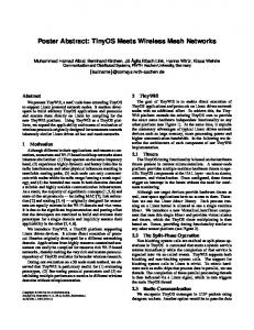
3.2 Problem formulation The assumptions below were made for the WMN in which the route selection scheme is expected to operate. Note that these assumptions do not conflict with any of the IEEE 802.11 specifications, and the frame format in the specifications is never changed. – All mesh routers in WMNs are stationary. – Assume that each mesh router has a set of 802.11 radio interfaces. The type of a radio interface can be either 802.11a [3], 802.11b [3], or 802.11g [3]. – A radio interface is always in one of four MAC states: SENDING, RECEIVING, IDLE and IDLE with TIMER. The transitions between these states are illustrated in Figure 3. The state IDLE with TIMER means that the radio is unused, but some neighboring mesh routers are using the same type of radio. – Each type of radio has a number of available channels. If a nearby mesh router is using a channel for communications, the state of the channel is set to be IN-USE. Otherwise, the state of the channel is set to be UNUSED. – Assume that the primary cause of packet loss is co-channel interference. The other factors that may affect the packet transmissions, such as multi-path fading [2], are assumed to be fixed by incorporating simple error recovery techniques (e.g., CRC [15]).
6
Table 2. Physical Characteristics 802.11b
802.11g
802.11a
Maximum rate
11Mbps
54Mbps
54Mbps
Transmission range
300 feet
250 feet
175 feet
(outdoor) Transmission range 100-150 feet 100-150 feet 100-150 feet (indoor) Non-overlapping ch
1, 6, 11
1, 6, 11
1 - 12
Spectrum
2.4GHz
2.4GHz
5GHz
Fig. 3. The State Transition Diagram of Radio Interface
– To simplify the hardware design and lower the cost, assume a mesh router does not have a large data buffer. Packets received by an intermediate mesh router are always quickly forwarded to the next hop. – The communications between mesh clients and their associated mesh router are assumed to be handled separately by a different set of wireless radio interfaces. In other words, in this research a route consists of only mesh routers. In WMNs, since each mesh router can be equipped with multiple radio interfaces, the traditional graph denotation is not sufficient to describe the network topology of a WMN. Before formulating the problem, consider the nomenclature used in this paper. A mesh-graph, GM = (VR , ER ), is composed of a set of node vectors VR and a set of link vectors ER . A node vector is defined as v =< n, r >, where n is a mesh router and r is one of n’s radio interfaces. A type function type(v) is defined to take a node vector v =< n, r > as its argument and return the type of radio r (i.e., 802.11a, b, or g) of mesh router n. A link vector < v1 , v2 >, where v1 =< ni , rp > and v2 =< nj , rq >, represents a mesh link between sender mesh router ni using radio interface rp to communicate with receiver mesh router nj using radio interface rq . Note that for a given mesh link < v1 , v2 >, the constraint type(v1 ) = type(v2 ) must be satisfied. The open neighbor set of a node vector N(v) (v =< n, r >) is defined as a set of mesh routers within transmission range of the radio transmission r of mesh router n, excluding n itself. As mentioned earlier, the transmission rate of an 802.11 wireless link may step down automatically when the signal strength is weakened. Since the signal strength is closely related to the distance between sender and receiver, the available bandwidth of a mesh link is formulated as follows. Given a link < v1 , v2 > where v1 =< ni , rp > and v2 =< nj , rq >, the available bandwidth of link < v1 , v2 >, denoted as b(< v1 , v2 >), is defined by Equation 1. In Equation 1, the available bandwidth of a link is inversely proportional to the physical distance between two ends of the link.
7
dist(ni , nj ) ) R (refer to Table 2 for maximum rate & transmission range, R) b(< vi , vj >) = M aximum rate · (1 −
(1)
In WMNs, a path χ connects the source node vector vs and the destination node vector vd and is composed of a set of ordered link vectors as follows. χ = {< vs , v1 >, < v10 , v2 >, · · · , < vh0 , vd >} 0 In a path, any two adjacent links < vk−1 , vk > and < vk0 , vk+1 >, where vk =< 0 ni , rp > and vk =< nj , rq >, should satisfy the constraint (ni = nj ) ∧ (rp 6= rq ). The path bandwidth of a path χ, denoted as B(χ), is defined as a function of the available bandwidths of the links in the path. Depending on the type of traffic along a path, the function may be defined differently. (Note that the terms path bandwidth and path throughput are identical and are used interchangeably in this paper.) Two types of traffic are considered in this paper: Burst Traffic (BT) and Constant Bit Rate (CBR) traffic. For the burst traffic, path bandwidth function is defined as the minimum available bandwidth of links in the path as, shown in Equation 2. If a path is assigned more bandwidth than the available bandwidth of any link in the path, an intermediate mesh router will have to buffer the data packets and this violates the no data buffer assumption. For instance, in Figure 2, path 2 has 3 links with 2Mbps, 5Mbps, and 1Mbps available bandwidth. Consequently, the path bandwidth of path 2 is 1Mbps.
0 B(χ) = min{b(< vs , v1 >), b(< v10 , v2 >), · · · , b(< vh−1 , vh >), b(< vh0 , vd >)} (2)
For CBR traffic, B(χ) is a constant value bc . Note that the available bandwidth of any of the links in the path has to be larger than bc . Let a set of all active connections be S, so the overall throughput Ball is defined as the sum of the path bandwidths of all the paths in S, as shown in Equation 3. The goal of this research is to design a route selection scheme to maximize overall throughput Ball of a WMN, which is the number of bits the WMN can transport between all source and destination pairs simultaneously. The higher the overall throughput Ball allows a WMN to support more end-user flows. Ball =
X
B(χ)
(3)
∀ χ∈S
3.3 Physical Layer Constraints To help formulate the physical layer constraints, we first define the radio state function and the channel state function must be defined. The radio state function rs(v) takes a node vector v = (n, r) as input parameter and returns the state (i.e., SENDING, RECEIVING, IDLE, and IDLE w/ TIMER) of the radio interface r of node n. The channel state function cs(v, c) takes a node vector v = (n, r) and a channel c as its
8
input parameters and returns the state of the channel c (i.e., IN-USE or UNUSED) for radio interface r of node n. Note that even if a radio is in IDLE or IDLE w/ TIMER state, a channel may still be the in IN-USE state if it is used by one of n’s neighbors. To establish a link < v1 , v2 >, where v1 =< ni , rp > and v2 =< nj , rq >, the physical layer constraints can be formulated as follows : 1. Before establishing link < v1 , v2 > Resource Allocation: (rs(v1 ) = IDLE ∨ rs(v1 ) = IDLE w/ TIMER) ∧ (rs(v2 ) = IDLE ∨ rs(v2 ) = IDLE w/ TIMER) ∧ ∃ ck cs(v1 , ck ) = cs(v2 , ck ) = UNUSED 2. After link < v1 , v2 > is established using channel ck Resource Allocation: rs(v1 ) = SENDING ∧ rs(v2 ) = RECEIVING Interference Avoidance: ∀ n ∈ N (v1 ) ∪ N (v2 ) cs(< n, r >, ck ) = IN-USE ∧ ∀ n ∈ N (v1 ) ∪ N (v2 ) \ {n1 , n2 } ∀ r if type(n, r) = type(ni , rp ) ⇒ rs(< n, r >) = IDLE w/ TIMER To successfully establish a link < vi , vj >, the components of the link vector and the neighboring routers should satisfy the above constraints. Some of the constraints need to be enforced by the DCF function (e.g., exchange RTS and CTS so the radio interfaces of neighbors will be in the IDLE w/ TIMER state) defined in the 802.11 specification [3]. 3.4 Cost and Throughput Metrics The purpose of WMN research is to facilitate rapid Internet access for a large number of mesh clients. Hence, network throughput should be the primary performance measurement. Since the number of radios and channels in WMNs is limited, if the impact of interference can be reduced when routing a traffic flow, the overall throughput can naturally be increased. In this subsection, two metrics used in our CARS scheme to evaluate a path are introduced, the cost metric that measures the degree of interference of a path, and the bandwidth metric that measures the throughput of a path. To measure the degree of interference of a path, compute the number of mesh routers that will experience interference along the path if the path is chosen for a connection and becomes active. If all candidate routes provide the same amount of bandwidth between source and destination, by selecting the path which creates the least interference, more network resources (e.g. radios and channels) can be utilized by other traffic flows. Given an active link < v1 , v2 > where v1 =< ni , rp > and v2 =< nj , rq >, the mesh routers in N (ni , rp ) cannot use the channel currently occupied by radio rp of node ni for communications (see interference avoidance physical layer constraint in
9
Subsection 3.3). Hence, the cost of using the link < v1 , v2 > can be defined as |N (v1 )|. For a given path χ = {e0 , e1 , · · · , ek } where ei =< vi0 , vi+1 >, the cost of a path C(χ) is defined as follows: C(χ) =
k X
|N (vi0 )|
(4)
i=0
The throughput of a path, on the other hand, is measured by the path bandwidth, B(χ), which has been defined in Subsection 3.2. In general, we prefer a path with lower cost and higher path bandwidth is preferable. When mesh routers are distributed uniformly, a shorter path contains a smaller number of hops and thus is likely to suffer less interference from neighbors. In addition, if a specific region has too many active communications, a path traversing that region is likely to result in a lower available path bandwidth. By choosing a path with a higher path bandwidth, a path that goes through a lighter traffic area can implicitly gain priority and load balancing can be achieved. 3.5 Traffic Aggregation In addition to path metrics, route selection also takes into account traffic aggregation. If a link is simultaneously used by multiple active connections, we say that traffic is aggregated on that link. Suppose that a link < v1 , v2 > is already a portion of an active connection. If the same link is reused by another connection, This will not create additional interference. In other words, the cost function of a path should take traffic aggregation into consideration. For a given path χ = {e0 , e1 , · · · , ek } where ei =< vi0 , vi+1 >, if a subset of links in the path S have already been used by other active connections, the cost function should be modified as in follows: C(χ) =
X
|N (vi0 )|
(5)
ei ∈χ\S
Additionally, the definition of the available bandwidth of a link needs to be modified so that the remaining bandwidth of a link can be utilized by aggregated traffic. Given a link < v1 , v2 >, let S be a set of active connections that includes the link, so the available bandwidth of link < v1 , v2 >, where v1 =< ni , rp > and v2 =< nj , rq >, is defined as follows: b(< v1 , v2 >) = M aximum Rate · (1 −
X dist(ni , nj ) )− B(χ) R
(6)
∀ χ∈S
(M aximum rate and transmission radius R are shown in Table 2)
For instance, suppose that in Figure 2 the links in path 2 have already been used by an active connection and the bandwidth of that path is 1Mbps. The available bandwidth of the first, second and third links of path 2 will then be 1Mbps, 4Mbps, and 0Mbps, respectively.
10
3.6 Proposed Cost-Aware Route Selection Scheme In this subsection, the proposed Cost-Aware Route Selection (CARS) scheme for WMNs is presented. The new scheme consists of two steps: radio selection and path selection. For a given source-destination pair and the sequence of intermediate mesh routers between them, the first step is to select the radio and channel to be used for the adjacent mesh routers in the sequence. (Note that according to our path definition, even with the same sequence of intermediate mesh routers, if the radio interface used by any intermediate mesh router is changed the path is considered to be different.) After the radio and channel used for have been intermediate mesh router are identified, a new path metric called CARS is then used to identify the path with the best bandwidth-cost ratio for communications. Given two adjacent mesh routers ni and nj in a sequence within close proximity, up to three sets of radio and channel will be returned as candidates for path consideration. First, the radio ni with the smallest transmission range (i.e., the smallest number of that neighbors interfere) and one of its unused channels is returned. If no channel of that radio channel is available or nj does not have an available radio channel with the matched type, the radio ni with the next smallest transmission range and one of its available channels is returned. This process continues until a set of radio and channel is found. Second, the radio ni with the highest available bandwidth and one of its unused channels is returned. Similarly, if no channel of that radio is available or nj does not have an available radio channel with the matched type, the radio of ni with the next highest available bandwidth and one of its available channel is returned. This process continues until a set of radio and channel is found. Last, these choices are examined to determine if there is an active link from ni to nj . If there is, the radio and channel used by the active link with the most remaining available bandwidth will be returned. After the radio selection step, each sequence of mesh routers between source and destination will produce a number of candidate routes. Given a pair of source and destination, the candidate routes (i.e., the sequence of intermediate mesh routers) are found by doing breadth-first search starting from the shortest path until the number of candidate routes reaches 10000. In Subsection 3.4, two metrics that measure the cost and bandwidth of a path have been introduced. In Equation 7, these two metrics are combined into one single Cost-Aware Route Selection (CARS) metric for path evaluation: CARS(χ) =
(B(χ))β (C(χ))α
(7)
In Equation 7, β is assumed to be 1 − α and 0 ≤ α, β ≤ 1. The greater the value of α, the more weight is put on cost for path selection. On the other hand, the greater the value of β, the more weight is put on path bandwidth for path selection. When α = β, the CARS metric represents the amount of earned bandwidth for a unit of interference cost. By comparing the CARS metrics for the candidate routes, it is possible to identify the most efficient path that produces the most bandwidth per unit of interference. Hence, Equation 7 captures our design goals. For instance, in Figure 2, if α is assigned a larger value (i.e., cost is heavily weighted), CARS will tend to favor path 5 as the sparse network area path 5 traverses has fewer neighbors to cause interference. On the other hand, if β is assigned a larger value (i.e.,
11
more weight is given to path bandwidth), CARS will tend to favor path 3. This is because, according to Equation 1, the available link bandwidth is inversely proportional to the distance between sender and receiver, so the dense network area that path 3 traverses, will tend to have a higher link bandwidth. Note that for CBR traffic, path bandwidth is a fixed value bc . Thus, Equation 7 can 1 be simplified as CARS(χ) = C(χ) . Consequently, the CARS metric will give priority to the path with the lower interference cost.
4 Simulation Result and Analysis This section presents the simulation results in order to evaluate the performance of the proposed CARS scheme. For the purpose of comparison, the other route selection schemes, including the shortest path and WCETT with different values of α and β, are implemented along with CARS by C++ on different hardware and environment configurations. 4.1 Simulation environment The simulations are conducted on a 400m by 400m two dimensional square. Mesh routers are randomly placed within this square region. Each mesh router in our simulation has a small number of radio interfaces. Each interface has a number of available channels. The channels from different types of radio can be either shared or exclusive. Two channels from different types of radio with the same ID are said to be shared if both radios utilize the same spectrum i.e., only one channel can be used at a time. Two channels from different types of radio with the same ID are said to be exclusive if radios are using different spectra i.e., both channels can be used simultaneously. The transmission rate of a link is determined by Equation 6 based on the type of radio and the physical distance between the two ends of the link. The transmission range of a radio is set according to the type of the radio and the location mesh routers (i.e., indoors or outdoors). The values used for the computation of the transmission rate and the transmission range can be found in Table 2. Two types of traffic flow, BT and CBR, are generated in the simulation. For a BT traffic flow, the rate is computed by Equation 2. For a CBR traffic flow, the rate is set to be 1024Kbps. Additionally, two different network flow patterns, Peer-to-Peer (P2P) and gateway-oriented, are simulated. In a P2P connection, source and destination are mesh routers randomly selected in WMNs. In a gateway-oriented connection, one of the few sinks are used as one end of the traffic flow. Since the primary cause of packet loss is co-channel interference, the ETT of a link in these candidate routes can simply be calculated as the inverse of the available bandwidth of the link. 4.2 Throughput of Traffic Patterns In this subsection, the simulation results of different route selection schemes on BT and CBR traffic are presented.
12 70000
6000
Throughput (Kbps)
50000
Average Throughput per Connection (Kbps)
Shortest-Path WCETT1 α=0.9 β=0.1 WCETT2 α=0.5 β=0.5 WCETT3 α=0.1 β=0.9 CARS1 α=0.9 β=0.1 CARS2 α=0.5 β=0.5 CARS3 α=0.1 β=0.9
60000
40000
30000
20000
10000
Shortest-Path WCETT1 α=0.9 β=0.1 WCETT2 α=0.5 β=0.5 WCETT3 α=0.1 β=0.9 CARS1 α=0.9 β=0.1 CARS2 α=0.5 β=0.5 CARS3 α=0.1 β=0.9
5000
4000
3000
2000
1000
0
0 40
50
60
70
80
90
100
40
50
Number Of Mesh Routers
60
70
80
90
100
Number Of Mesh Routers
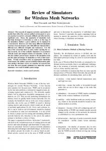
Fig. 4. Throughput w/ BT, 3 NICs & 3 exclusive channels, P2P, indoors
Fig. 5. Average Throughput per Connection w/ BT, 3 NICs & 3 exclusive channels, P2P, indoors
100
Successful Connection Rates (%)
Successful Connection Rates (%)
100
Shortest-Path WCETT1 α=0.9 β=0.1 WCETT2 α=0.5 β=0.5 WCETT3 α=0.1 β=0.9 CARS
80
60
40
20
Shortest-Path WCETT2 α=0.5 β=0.5 CARS
80
60
40
20
0
0 40
50
60
70
80
90
100
Number Of Mesh Routers
Fig. 6. Successful Connection Rates w/ CBR, 3 NICs & 3 exclusive channels, P2P, indoors
4
6
8
10
12
14
Number of Generated Connections
Fig. 7. Successful Connection Rates w/ 80 mesh routers (3 work as gateway), CBR, 2 NICs & 3 shared channels, indoors
Figure 4 shows the overall network throughput Ball for the different route selection schemes for the burst traffic scenario based on the number of mesh routers in the simulated region. In the simulations, a mesh router is set to have 3 Network Interface Card (NIC) radios, and each radio has 3 exclusive channels. P2P connections are generated until the network is saturated. The location of the simulated WMN is assumed to be indoors. As illustrated in Figure 4, no matter what values of α and β are used in CARS and WCETT, CARS can always produce more than twice as much of the overall network throughput as WCETT’s and the shortest path’s. This is a big improvement over the past route selection schemes. While all three different CARS versions have similar performance, the that with α = 0.1 and β = 0.9 is slightly better than the other two. This suggests that the path bandwidth metric is slightly more important than the path cost metric. Additionally, the overall network throughput of the three different CARS versions is a lot more responsive to an increase of the number of mesh routers in any of the simulated region than the other route selection schemes. This suggests that the new CARS scheme is more scalable in terms of overall throughput. This feature is especially important for WMNs. In addition, Figure 5 shows the average path throughput of differ-
13
100
Shortest-Path WCETT2 α=0.5 β=0.5 CARS Successful Connection Rates (%)
Successful Connection Rates (%)
100
80
60
40
20
Shortest-Path WCETT2 α=0.5 β=0.5 CARS
80
60
40
20
0
0 4
6
8
10
12
14
Number of Generated Connections
Fig. 8. Successful Connection Rates w/ 80 mesh routers (3 work as gateway), CBR, 2 NICs & 3 exclusive channels, outdoors
4
6
8
10
12
14
Number of Generated Connections
Fig. 9. Successful Connection Rates w/ 80 mesh routers (3 work as gateway), CBR, 2 NICs & 3 exclusive channels, indoors
ent route selection schemes with respect to the number of mesh routers in the simulated region under the same simulation settings. As illustrated in Figure 5, the schemes that produce the highest average path throughput are CARS with α = 0.1 and β = 0.9, WCETT with α = 0.1 and β = 0.9, and WCETT with α = 0.5 and β = 0.5. The average path throughput of CARS with α = 0.5 and β = 0.5 and WCETT with α = 0.9 and β = 0.1 is just slightly lower than the highest group. It is interesting to observe from Figure 5 that CARS with α = 0.1 and β = 0.9 achieves a significant improvement in the overall network throughput without sacrificing individual path throughput. Figure 6 shows the successful connection rates for different route selection schemes in the case of the CBR traffic scenario with respect to the number of mesh routers. In these simulations, each mesh router is set to have 3 NIC radios, and each radio has 3 exclusive channels. 20 P2P-type connections are attempted. The location of the simulated MWN is also assumed to be indoors. Note that for the CBR scenario, the CARS metric is essentially reduced to the path cost function. As illustrated in Figure 6, no matter what values of α and β are used in WCETT, CARS can successfully establish more than twice as many connections as either WCETT as the shortest path. This suggests that the cost metric still plays a crucial role in route selection. Additionally, the results of this simulation suggest that CARS allows more mesh clients to be supported than either WCETT or the shortest path. This feature is also very important for WMNs. 4.3 Successful Connection Rates of Shared and Exclusive Channels In this subsection, the simulation results of different route selection schemes for shared and exclusive channels are presented. Here, each mesh router is set to have 2 NIC radios, and each radio has 3 channels. The network size is fixed at 80 routers with the assumption that 3 of them work as gateways to connect to the Internet. Gatewayoriented CBR connections are used and the WMN is assumed to be indoors. Figure 7 shows the successful connection rates of different route selection schemes with respect to the number of generated connections in the simulated region in the case of the shared channels. As illustrated in Figure 7, CARS has more than twice of the
14
successful connection rate of either WCETT’s or the shortest path. This suggests that CARS also performs well for the gateway-oriented connections. However, when the number of generated connections increases, the successful connection rates for CARS decreases. This is because the wireless resource (i.e., radios and channels) close to the gateways is quickly exhausted. Figure 9 shows the successful connection rates of different route selection schemes with respect to the number of generated connections in the simulated region in case of the exclusive channels. In Figure 9, the successful connection rates for CARS are approximately three times the rates for WCETT and the shortest path. This is because the assumption of exclusive channels actually means less possibility of interference. In other words, more resources are available in the case of the exclusive channels. When Figure 7 and Figure 9 are compared together, it can be seen that the successful connection rates of the other route selection schemes are not sensitive to the extra resources than become available when the channel type switches from shared to exclusive. This suggests that CARS can better utilize the extra resources in the network. For the purpose of comparison, Figure 8 shows the successful connection rates of different route selection schemes with respect to the number of generated connections in the simulated region for the case of exclusive channels under the same configuration, with the only difference being that the network is located outdoors. As can be seen, the rates in Figure 8 are slightly lower than the rates in Figure 9. Because in the outdoor case, the transmission range is increased, as indicated in Table 2. At the same time, more interference will be created when a path is established. 4.4 Network Throughput of Different Number of Radios and Channels In this subsection, the simulation results of different route selection schemes on different number of NIC radios and channels are presented. Figure 10 shows the overall network throughput Ball of different route selection schemes with respect to the number of NIC radios at each mesh router. In this set of simulations, the hardware and environment settings are similar to those used to for Figure 4 except that each NIC radio is set to have 2 channels and the network size is set to be 80. As illustrated in Figure 10, no matter how many NIC radios are available at a mesh router, the overall network throughput of any CARS is always more than 1.7 times that of either WCETT or the shortest path. In addition, as the number of radios at each mesh router increases, the overall network throughput of both CARS with α = 0.1 and β = 0.9 and CARS with α = 0.5 and β = 0.5 increases faster than the other route selection schemes. This again suggests that with proper selection of the values of α and β, CARS is more scalable in terms of the number of available NIC radios at each mesh router. Figure 11 shows the overall network throughput Ball of the different route selection schemes with respect to the number of available channels for each radio. In this set of simulations, the hardware and environment settings are the same as those used for Figure 10. As illustrated in Figure 11, no matter how many channels are available at each radio, the overall network throughput of CARS is always more than twice that of either
15 90000
90000 Shortest-Path WCETT1 α=0.9 β=0.1 WCETT2 α=0.5 β=0.5 WCETT3 α=0.1 β=0.9 CARS1 α=0.9 β=0.1 CARS2 α=0.5 β=0.5 CARS3 α=0.1 β=0.9
80000
70000
60000
Throughput (Kbps)
Throughput (Kbps)
70000
Shortest-Path WCETT1 α=0.9 β=0.1 WCETT2 α=0.5 β=0.5 WCETT3 α=0.1 β=0.9 CARS1 α=0.9 β=0.1 CARS2 α=0.5 β=0.5 CARS3 α=0.1 β=0.9
80000
50000 40000 30000 20000
60000 50000 40000 30000 20000
10000
10000
0
0 2
3
4
5
Number of NIC
Fig. 10. Throughput w/ 80 mesh routers, BT, 2 exclusive channels, P2P, indoors
3
4
5
6
Number Of Channels
Fig. 11. Throughput w/ 80 mesh routers, BT, 3 NICs, P2P, indoors
WCETT or the shortest path. Again in Figure 11, CARS with α = 0.1 and β = 0.9 and CARS with α = 0.5 and β = 0.5 outperform the other route selection schemes.
5 Conclusion and Future Works In this paper, a novel route selection scheme, namely Cost-Aware Route Selection, is proposed for WMNs to improve the overall throughput. The scheme incorporates a path metric which captures the bandwidth and cost ratio and the introduces idea of traffic aggregation. Simulation results show that the new CARS scheme improves the overall throughput by up to 165% in the case of the burst traffic and boosts the number of connections by up to 300% in the case of constant bit rate traffic and is also more scalable in terms of the size of the network compared to both WCETT and the shortest path route selection schemes. Although for a given set of candidate routes this scheme is able to identify the best choice to improve overall network throughput, it has yet to completely solve the routing issue as no protocol is provided to locate those candidate routes. In addition, the new route selection scheme is centralized in the sense that the source node must collect and process all the necessary information. While the nature of WMNs (i.e., mesh routers are fixed and connected to external power supplies) allows this assumption to hold, future research on a distributed routing protocol that runs only on the basis of localized information would definitely be of interest.
References 1. Ian F. Akyildiz, and Xudong Wang, A Survey on Wireless Mesh Networks, IEEE Radio Communications, September 2005. 2. C.Siva Ram Murthy and B.S. Manoj, Ad Hoc Wireless Networks :Architechtures and Protocols, Peason Education, ISBN 013147023X, 2004 3. IEEE 802.11 The working group setting the standards for Wirless LANs, http://grouper.ieee.org/groups/802/11/
16 4. K. M. Alzoubi, P.-J. Wan, and O. Frieder. Message-optimal connected-dominating-set construction for routing in mobile ad hoc networks. In Proceedings of the Third ACM International Symposium on Mobile Ad Hoc Networking and Computing, June 2002 5. F. Kuhn, R. Wattenhofer and A. Zollinger, Ad-hoc networks beyond unit disk graphs, Proceedings of the 2003 joint workshop on Foundations of mobile computing citation 2003, San Diego, CA, U.S., 2003 6. K. Siwiak, Advances in Ultra-Wide Band Technology, Radio Solutions 2001, London, November 2001. 7. M. Alicherry, R. Bhatia, and L. Li, Joint channel assignment and routing for throughput optimization in multi-radio wireless mesh networks, MobiCom’05, Cologne, Germany, August 28-September 2, 2005. 8. A. Raniwala, K. Gopalan, and T. Chiueh, Centralized Channel Assignment and Routing Algorithms for Multi-Channel Wireless Mesh Networks, ACM Mobile Computing and Communications Review (MC2R) Vol 8, No 2 April ’04. 9. A. Raniwala and T. Chiueh, Architecture and Algorithms for an IEEE 802.11-Based MultiChannel Wireless Mesh Network, in Infocom, 2005 10. D.S.J. De Couto, D. Aguayo, J. Bicket, and R. Morris, A High-Throughput Path Metric for Multi-Hop Wireless Routing, Proceedings of the 9th ACM International Conference on Mobile Computing and Networking (MobiCom ’03), San Diego, California, September 2003. 11. R. Draves, J. Padhye, and B. Zill, Routing in multi-radio, multi-hop wireless mesh networks, Proceedings of ACM MobiCom, Philadelphia, PA, September 2004. 12. R. Draves, J. Padhye, and B. Zill, Comparisons of Routing Metrics for Static Multi-Hop Wireless Networks, ACM Annual Conf. Special Interest Group on Data Communication (SIGCOMM), Aug. 2004, pp. 133.44. 13. D. B. Johnson, D. A. Maltz, and Y-C Hu, The Dynamic Source Routing Protocol for Mobile Ad Hoc Networks (DSR), IETF Mobile Ad Hoc Networks Working Group, Internet Draft, work in progress, 24 February 2003. 14. Infopeople Webcasts, http://www.infopeople.org/training/webcasts/03-0105/Wireless Webcast.ppt 15. D.V. Sarwate, Computation of Cyclic Redundancy Check via Table Look-Up, Communications of the ACM, Vol.31 No.8, 1988.