CC=Conveyor Capacity in Kg/sec. V =Belt Speed in m/sec. H =Conveyor height in m. L =Conveyor length in m mi =Mass of a set of idlers in Kg l =Idler Spacing ...
Available online www.jsaer.com Journal of Scientific and Engineering Research, 2016, 3(5):174-182 Research Article
ISSN: 2394-2630 CODEN(USA): JSERBR
Cost Effective Recognition and Classification of Moving Objects using Simulink Farzan Majeed Noori1, Liaquat Ali Khan2, Rayyan Azam Khan1 1
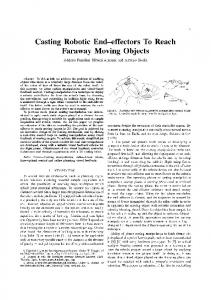
Department of Mechatronics Engineering, Air University, E-9 PAF Complex, Islamabad 44000, Pakistan 2 Department of Mechanical Engineering, Capital University of Science and Technology Islamabad Expressway, Pakistan Abstract Conventional surveillance systems require human intervention to monitor thus they are not applicable for a long term monitoring. The real hurdle that still exists in industry is to make a simple sorting mechanism that is not only simple but inexpensive as well. It is also compact and easy to implement in any type of environment. This paper deals with an intelligent image processing method for a real-time surveillance system that needs to detect multiple moving objects robustly against noises and environment. So the proposed method uses red-green-blue (RGB) colour background modeling with a sensitivity parameter to extract moving regions, the filters to eliminate noises, and blob-analysis to differentiate among the moving objects. The propose model is inexpensive to build and can be easily applied in any environment. Image is taken using Dlink 932L camera and processed. The results obtained with the proposed approach is satisfactory in performance. This method is applicable for sorting objects in industry making different shapes of products. Keywords Image Processing, RGB, Modeling, Filter, Blob Analysis Introduction In industry the object sorting is always a problem and some of the bigger industries are facing drastic difficulties due to which their products are not sorted properly and they receive a lot of complaints. The companies are losing their pride, so in order to minimize such problematic situations such a system is designed which can overcome these problems. The use of robots in industry is increasing rapidly owing to the fact of their ability to carry out task relentlessly with great speed and precision. They are practically sagacious and can perform task with the help of some supervision [1-2]. Additionally, it plays a vital role in hazardous areas. Likewise, Robotic arm can be used for numerous tasks such as drilling, placing, assembling and many more [1]. Supervision can be done through a number of ways like sensor conditioning, Image processing and many more. Comparatively supervision through image processing is more precise [3]. Pixels obtained in image processing provide leading information about object recognition [4]. Image processing can be done in many ways like through MATLAB® [5-6] or embedded technique, but our target is to achieve a simple and effective recognition scheme that can be used to signify and match images on the base of size. We have demonstrated a scenario in which we would be able to sort objects on classifications of their size and shape using a robotic arm and a camera replicating the functionality of human hands and eyes [7-8]. The robotic arm is operated using RC servo motors controlled terminally using a controller. The camera optimized with the robot deals with capturing of image and sending it directly to computer. MATLAB ® identifies the object and produces a real time output to the robotic arm on basis of the configuration of the object on the conveyer belt. The arm thus segregates this object accordingly [9-10]. Journal of Scientific and Engineering Research 174
Rim-Rukeh A
Journal of Scientific and Engineering Research, 2016, 3(5):174-182
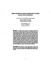
This sorting technique was implemented on two types of objects, circular and rectangular. The positions for placing the objects are fixed and known. Buckets are placed for each type of the object. After placing the object in its destination, robotic arm returns to its original position [11]. Process flow of research project is shown in figure 1. The objects are coming on conveyor belt while the camera is used to detect an image of an object in active position. Image is transferred to computer by serial transfer. Image is then processed using MATLAB® Simulink. The image is processed and further filtered to remove noise using filters as shown in figure 14 & 15. The object is sorted on basis of less than or greater than 15000 pixels as shown in figure 3 & 4. Once the pixels are detected the object is sorted using robotic arm [11].
Figure 1: Process Flow of the Project Nomenclature CC=Conveyor Capacity in Kg/sec V =Belt Speed in m/sec H =Conveyor height in m L =Conveyor length in m mi =Mass of a set of idlers in Kg l =Idler Spacing in m mb =Load due to belt in Kg/m mm =Load due to conveyed materials in Kg/m δ =Inclination angle of the conveyor in degree f =Coefficient of friction Ks =Start-up factor Kd=Drive Efficiency Cr =Friction factor Tb =Steady state belt tension in N Tbs =Belt tension while starting in N PP =Power at drive pulley in Kw Pm=Minimum motor power in Kw Bs=Breaking belt strength in N A= Acceleration in m/sec2 Cv =Breaking Strength loss factor 𝒂𝒊 =the distance from 𝑍𝑖 𝑡𝑜 𝑍𝑖−1 measured along 𝑋𝑖 𝜶𝒊 =the angle from 𝑍𝑖 𝑡𝑜 𝑍𝑖−1 measured about 𝑋𝑖 𝒅𝒊 =the distance from 𝑋𝑖 𝑡𝑜 𝑋𝑖−1 measured along 𝑍𝑖 𝜽𝒊 =the angle from 𝑋𝑖 𝑡𝑜 𝑋𝑖−1 measured about 𝑍𝑖 Detection Module Image acquisition and image processing are considered to be one of the essential parts of the project as they are the backbone if data is not processed properly it may lead to the failure of the system. Hence, in order to maximize the chances of success MATLAB®, it comes with efficient tools and processes the data without any major delay. Journal of Scientific and Engineering Research 175
Rim-Rukeh A
Journal of Scientific and Engineering Research, 2016, 3(5):174-182
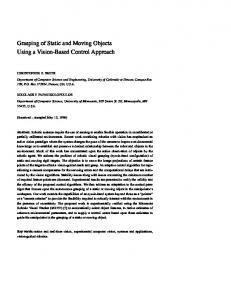
Simulink® a tool of MATLAB ® was used to implement the image processing [12-13]. As Simulink® comes with the built in functions/blocks for the video and image processing the work became quite easy, though it was challenging to get a hand on the basic operations. The figure 2 illustrates the work done on the Simulink ® that how the object was detected even without using any sensor at the start of the conveyor belt and how the image processing was handled.
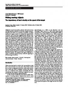
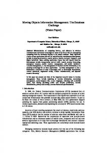
Figure 2: Process Flow of Image Processing Recognition Module The image processing technique was implemented on two types of objects one is the circular, and the other one is the rectangular object. Video is received by camera in Simulink® so, whenever an object comes an image is captured and image processing techniques are implemented [14-16]. At first, the image captured is in RGB it is converted into grey code, and then it is converted into a binary image by applying an auto threshold. The binary image has some noises in the background as it could be seen in figure 14. Using median filter this noise was removed as shown in figure 15 [17]. The Blob analysis was used to detect moving object, differentiate circular and rectangular object as shown in figure 3 & 4. Image pixels were compared on next stage and operation was performed as required. Simulink model of image processing is shown in figure 5.
Figure 3: Binary Image of Circular Object
Figure 4: Binary Image of Rectangular Object
Journal of Scientific and Engineering Research 176
Rim-Rukeh A
Journal of Scientific and Engineering Research, 2016, 3(5):174-182
Figure 5: Image Processing Simulink Code Post Processing Binary image with some noises is shown in figure 6. The noises in the image are removed by using a median filter. The filtered binary image is analysed over an area which determines what type of object is received. The figure 7 shows the results of the filtered image [18]. After got the processed image we need to identify the object.The shapes are identified using the area analysis. Once the shape is known a signal is sent serially from the Simulink® via Arduino Uno (Microcontroller) to the manipulator. The robotic arm then picks the object from the conveyor belt and places it in its respective position.
Figure 6: - Binary Image of Circular Object with Figure 7 - Binary Image of Circular Object after Noise Filter Conveyor Belt A conveyor belt (or belt conveyor) consists of two or more pulleys, with a continuous loop of material the conveyor belt that rotates about them. One or both of the pulleys are powered, moving the belt and the material on the belt forward. The powered pulley is called the drive pulley while the unpowered pulley is called the idler. There are two main industrial classes of belt conveyors; those in general material handling such as those moving boxes along inside a factory and bulk material handling such as those used to transport industrial and agricultural materials, such as grain, coal, ores, fines and lumps material. Conveyors are durable and reliable components used in automated distribution and warehousing. In combination with computer controlled pallet handling equipment this allows for more efficient retail, wholesale, and manufacturing distribution. It is considered a labour saving system that allows large volumes to move rapidly through a process, allowing companies to ship or receive higher volumes with smaller storage space and with less labour expense. Figure 8 shows the conveyor belt used in the research project [19-20].
Journal of Scientific and Engineering Research 177
Rim-Rukeh A
Journal of Scientific and Engineering Research, 2016, 3(5):174-182
Figure 8: Conveyor belt Robotic Arm A simple 3D-Link robotic arm with 2 DOF (Degree of Freedom) was designed and fabricated as shown in figure 9. RC Servo motors were used for required displacement and feedback control. The links were fabricated using aluminum having 1 DOF each while Arduino controller was used for its operation [21].
Figure 9: 3D-Link Robotic Arm with 2 DOF Mathematical modeling Conveyor Belt The basics of the Calculations of Conveyor Belt Design Parameters: Load due to idlers (mi): This can be calculated as below [20] Belt Tension: 𝐦𝐢 =
(𝐦𝐚𝐬𝐬 𝐨𝐟 𝐚 𝐬𝐞𝐭 𝐨𝐟 𝐢𝐝𝐥𝐞𝐫𝐬) (𝐢𝐝𝐥𝐞𝐫𝐬 𝐬𝐩𝐚𝐜𝐢𝐧𝐠)
(1)
The belt of the conveyor always experience a tensile load due to the rotation of the electric drive, weight of the conveyed materials, and due to the idlers. The belt tension at steady state can be calculated as [19] 𝐓𝐛 = 𝟏. 𝟑𝟕 × 𝐟 × 𝐋 × 𝐠 × 𝟐 × 𝐦𝐢 𝟐 × 𝐦𝐛 + 𝐦𝐦 × 𝐜𝐨𝐬 𝛅 + (𝐇 × 𝐠 × 𝐦𝐦) (2) Belt tension while starting the system: Initially during the start of the conveyor system, the tension in the belt will be much higher than the tension in steady state. The belt tension while starting can be calculated as [20]: Power at drive pulley: The power required at the drive pulley can be calculated from the belt tension value as below [20]: 𝐓𝐛𝐬 = 𝐓𝐛 × 𝐊𝐬 (𝐓𝐛 × 𝐕) 𝐏𝐏 = 𝟏𝟎𝟎𝟎
(3) (4)
Journal of Scientific and Engineering Research 178
Rim-Rukeh A
Journal of Scientific and Engineering Research, 2016, 3(5):174-182
Sizing of the motor: The minimum motor power can be calculated as [20]: Acceleration 𝐏𝐦 =
𝐏𝐏 𝐊𝐝
(5)
The acceleration of the conveyor belt can be calculated as [20]: (𝐓𝐛𝐬 − 𝐓𝐛 ) 𝐀= [𝐋 × (𝟐 × 𝐦𝐢 + 𝟐 × 𝐦𝐛 + 𝐦𝐦)]
(6)
Belt breaking strength: This parameter decides the selection of the conveyor belt. The belt breaking strength can be calculated as [20]: (𝐂𝐫 × 𝐏𝐏 ) 𝐁𝐒 = (7) (𝐂𝐕 × 𝐕) Its value is used to select the conveyor belt from the manufacturer’s catalogue. Robotic Arm Forward Kinematics The forward kinematics is used to determine the position of the robotic arm. In forward kinematics the joint angles are known, and final position is found using these known joint angles. The Denavit-Hertenberg (D-H) parameters are the most important parameters whenever the kinematics equations are to be found. The table gives out the D-H parameter [22]. The transformation equation starting from the link i (base) till the link i+1 Table 1: D-H Parameters i 𝜶𝒊−𝟏 𝒂𝒊−𝟏 𝒅𝒊 𝜽𝒊 1 0 0 0 𝜃1 2 -90 0 0 45 3 0 0 𝑙1 𝜃3 4 0 0 0 𝑙2
0.707c1 c 3 s 3 0.707c 3 s 3 - s1 0.707 s c s 0.707 s c s c 1 3 3 1 3 3 1 0 4T 0.707c 3 s 3 0.707- c 3 s 3 0 0 0 0
0.707c1 c 3l2 l1 s 3l2 0.707 s1 c 3l2 l1 s 3l2 0.707c 3l2 l1 s 3l2 1
(8)
Pro/Engineer® design of Robotic Arm 3D model of robotic arm was designed using Solid Works ® before fabrication. Figure 10 & 11 show the side and front view while figure 12 &13 shows top and isometric view of model.
Figure 10: Side View of robotic arm
Figure 11: Front View of robotic arm
Journal of Scientific and Engineering Research 179
Rim-Rukeh A
Journal of Scientific and Engineering Research, 2016, 3(5):174-182
Figure 12: Top View of robotic arm
Figure 13: Isometric View of robotic arm
Robotic Arm Workspace Forward kinematics results are manipulated using MATLAB ®. The results obtained in 2D and 3D are illustrated in figures 14 &15. The graphs plotted indicate the workspace that manipulator could reach. The lines show the reachable workspace of the manipulator and the regions where there are no lines are the one where joint singularities can occur [23].
Figure 14: 2D Plot of workspace
Figure 15: 3D Plot of workspace Conclusion and Future Recommendation Object sorting has been done very accurately on basis of image processing and implemented in industry with very less cost. The proposed research model is very accurate as compared to sorting on basis of weight or size so
Journal of Scientific and Engineering Research 180
Rim-Rukeh A
Journal of Scientific and Engineering Research, 2016, 3(5):174-182
chances of error in industry can be minimized using proposed model. PID (Proportional Integral Derivative) can be used for uniform motion of robotic arm. Image processing can be done using different methods like edge detection etc. Constraint of two objects sorting only, can be overcome by using edge detection method. References [1]. Goldy Katal1, Saahil Gupta2, Shitij kakkar3 “Design And Operation Of Synchronized Robotic Arm” Volume:02 Issue:08 Aug |2013 [2]. Zol Bahri Razali, Gunasegaran, “An Application of Image Processing for Automated Mixed Household Waste Sorting System”, International Conference on Man Machine Systems (ICoMMS2012), Penang. MALAYSIA, 2012. [3]. Y.H. Tsai,D. Stow and J. Weeks, “Comparison of Object-Based Image Analysis Approaches to Mapping New Buildings in Accra, Ghana Using Multi-Temporal Quick Bird Satellite Imagery”, Int J Remote Sens. 3(12), 2707–2726 (2011). [4]. Aashik Chandramohan, Krishna Murthy K.R., Sowmya G. , Surya Prasad P.A., Vijay Krishna V., Peeyush K.P., “Cost Effective Object Recognition and Sorting Robot Using Embedded Image Processing Techniques”, International Journal of Innovative Technology and Exploring Engineering (IJITEE) ISSN: 2278-3075, Volume-3, Issue-11 April 2014. [5]. M. Bister, C.S. Yap, K.H. Ngand C.H. Tok, “Increasing the speed of medical image processing in MatLab”, Biomed Imaging Interv J. 3(1), e9 (2007). [6]. J. Courtney, E. Woods,D. Scholz,W.W. Hall and V.W. Gautier, “MATtrack: A MATLAB-Based Quantitative Image Analysis Platform for Investigating Real-Time Photo-Converted Fluorescent Signals in Live Cells”, PLoS One. 10(10), e0140209 (2015). [7]. P. P. Chavan1, S.M. Kale, P.P.Gaikwad , S. M. Ghadge “INTELLIGENT OBJECT SORTING INSOLENT SYSTEM”, International Conference on Pervasive Computing (ICPC),IEEE,2015. [8]. Vindhya Devalla ,Rajesh Singh, “Design and Development of Object Recognition and Sorting Robot for Material Handling in Packaging and Logistic Industries”, International Journal of Science and Advanced Technology (ISSN 2221-8386) Volume 2 No 9 September 2012. [9]. Uzma Amin1, Ghulam Ahmad2, Nudrat Liaqat3, Manzar Ahmed4 , Sumbal Zahoor5, “ Detection & Distinction of Colors using Color Sorting Robotic Arm in a Pick & Place Mechanism,” Paper ID: 020131882 Volume 3 Issue 6 International Journal of Science and Research (IJSR), June 2014 pp.no1164-1168. [10]. Jong Sun Kim, Dong Hae Yeom, and Young Hoon Joo, “Fast and Robust Algorithm of Tracking Multiple Moving Objects for Intelligent Video Surveillance Systems”,IEEE,2011 [11]. D. B. Rane, Gunjal Sagar S, Nikam Devendra V, Shaikh Jameer U, “Automation of Object Sorting Using an Industrial Robo arm and MATLAB Based Image Processing”, International Journal of Emerging Technology and Advanced Engineering,Volume 5, Issue 2, February 2015. [12]. A. Kamboj and A. Gupta, “Simulink Model Based Image Segmentation”, International Journal of Advanced Research in Computer Science and Software Engineering. 2, 6 (2012). [13]. A. GUPTA, “HARDWARE SOFTWARE CO-SIMULATION FOR TRAFFIC LOAD COMPUTATION USING MATLAB SIMULINK MODEL BLOCKSET”, International Journal of Computational Science and Information Technology. 1, 2 (2013). [14]. V.B.Raskar, Nilesh Hargude, Sabale Vishwanath, krishna Chavan, “PRACTICAL APPLICATIONS OF ROBOTIC HAND USING IMAGE PROCESSING”, International Journal of Advanced Research in Computer Engineering & Technology (IJARCET) Volume 4 Issue 3, March 2015. [15]. A.W.L. Dickinson, P. Abolmaesumi, D.G. Gobbi and P. Mousavi, “SimITK: Visual Programming of the ITK Image-Processing Library within Simulink”, J Digit Imaging. 27(2), 220–230 (2014). [16]. K. Wang,M.L. Steyn-Ross,D.A. Steyn-Ross, M.T. Wilson,J.W. Sleigh and Y. Shiraishi, “Simulations of pattern dynamics for reaction-diffusion systems via SIMULINK”, BMC Syst Biol. 8, 45 (2014).
Journal of Scientific and Engineering Research 181
Rim-Rukeh A
Journal of Scientific and Engineering Research, 2016, 3(5):174-182
[17]. M. Sigdel,M.L. Pusey and R.S. Aygun, “Real-Time Protein Crystallization Image Acquisition and Classification System”, Cryst Growth Des. 13(7), 2728–2736 (2013). [18]. Mayur Salve, Dinesh Repale, Sanket Shingate, Divya Shah, “SIMULINK based Moving Object Detection and Blob Counting Algorithm for Traffic Surveillance”, International Journal of Computer Applications (0975 – 8887) Volume 70– No.17, May 2013. [19]. O. Adeodu, O. M. Dada, “Design of a Material Handling Equipment: Belt Conveyor System for Crushed Limestone Using 3 roll Idlers”, JOURNAL OF ADVANCEMENT IN ENGINEERING AND TECHNOLOGY, January 16, 2014. [20]. Ghazi Abu Taher, Yousuf Howlader, Md. Asheke Rabbi, Fahim Ahmed Touqir, “Automation of Material Handling with Bucket Elevator and Belt Conveyor”, International Journal of Scientific and Research Publications, Volume 4, Issue 3, March 2014 1 ISSN 2250-3153. [21]. Jasjit Kaur, Dr. V K Banga, “Simulation of Robotic Arm having three link Manipulator”, International Journal of Research in Engineering and Technology (IJRET) Vol. 1 No. 2 March, 2012 ISSN: 22774378. [22]. VIVEK DESHPANDE , P M GEORGE, “KINEMATIC MODELLING AND ANALYSIS OF 5 DOF ROBOTIC ARM”, International Journal of Robotics Research and Development (IJRRD) ISSN(P): 2250-1592, ISSN(E):2278–9421, Vol . 4, Issue 2, Apr 2014, 17-24. [23]. Y. D. Patel , P. M. George, “PERFORMANCE MEASUREMENT AND DYNAMIC ANALYSIS OF TWO DOF ROBOTIC ARM MANIPULATOR”, International Journal of Research in Engineering and Technology eISSN: 2319-1163, pISSN: 2321-7308.
Journal of Scientific and Engineering Research 182