Counteracting DDoS Attacks In Multiple ISP Domains Using Routing Arbiter. Architecture. Udaya Kiran ..... agents to other controller, which we call the Master controller. ... Routing Arbiter Network Operations Center (RA-NOC):. The main ...
Counteracting DDoS Attacks In Multiple ISP Domains Using Routing Arbiter Architecture Udaya Kiran Tupakula
Vijay Varadharajan
Information and Networked Systems Security Research Division of Information and Communication Sciences Macquarie University, Sydney, Australia-2109 {udaya, vijay}@ics.mq.edu.au
Abstract-Today Distributed Denial of Service (DDoS) attacks are causing major threat to perform online business over the Internet. Our previous work proposed an automated model with a new packet marking technique and agent design to counteract DDoS within a single ISP domain. Our approach has many features that are required to minimize the DDoS attacks. For example, our model is invoked only during attack times, identifies the approximate source of attack with a single packet even in case of spoofed source address, identifies different attack signatures for different attacking sources, prevents the attack nearest to the attacking source, has very fast response for any changes in attack traffic pattern, is simple in its implementation and can be incrementally deployed. Though the proposed model has several advantages, prevention of the attack is limited to a single ISP domain. In this paper we extend our model to prevent DDoS attacks in multiple ISP domains by retaining all the advantages achieved in our previous work. We also propose a practical implementation of the extended model with a presently working architecture.
I. INTRODUCTION Denial-of -Service (DoS)[1,2] is an attempt by attackers to prevent access to resources by legitimate users for which they have authorization. DoS on the Internet has become a pressing issue following a series of attacks during recent times. Several papers [1,3] have reported on the prevalence of such attacks on commercial servers and ISPs and the disruption they cause to services in today’s Internet. In case of distributed denial of service (DDoS), an attacker compromises several hosts on the Internet. Often, these are weakly secured machines and they are broken into using well-known defects in standard network service programs and common operating systems. These compromised computers are referred to as zombies. The attacker then uses these compromised computers to launch a coordinated attack on the victim machines. Recently several schemes have been proposed on how to detect and prevent some of these types of attacks, but they suffer from a range of problems, some of them being impractical and others not being effective against these attacks. Further the proposed schemes deal only with some part of the distributed denial of service problem. For instance, [4,5] propose techniques to prevent traffic with spoofed address from crossing the border, while some others [6,7,8,9,10,11] propose techniques to trace back the approximate source of the attacking system even in the case of spoofed source address. The work in [12] proposes a technique to automatically identify the attack at the congested router and treats the traffic by punishing only the identified aggregates that are causing congestion.
Our previous work [13] proposed an automated model that deals with the overall DDoS problem. The paper discusses techniques to identify the attack at the victim, trace the approximate source of attack even in case of spoofed source address, prevent the attack traffic closest to the attacking source and automatically tune to any changes in the attack traffic. This approach is based on controller-agent model and has several advantages compared to other proposed techniques. However our previous model only considered prevention of DDoS attacks within a single ISP domain. The paper is organized as follows. Section II gives an overview of our previous model. Section III extends the model to support the prevention of DDoS attacks in multiple ISP domains. Section IV proposes implementation of the extended model with a currently working architecture and section V concludes. II.
OUR PREVIOUS MODEL
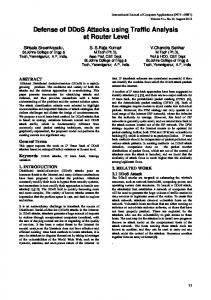
Our previous work [13] considers an architecture that is divided into ISP domains and customers are connected to these ISP domains. Routers are divided into internal routers and external routers. Internal routers belong to the ISP and external routers belong to the customers or another ISP. Internal routers themselves can be of two types, namely edge routers and transit routers. Edge routers are internal routers that are adjacent to one or more external routers. Transit routers are internal routers that are only adjacent to other internal routers. In Fig: 1 (R0, R3, R4, R5, R6) are edge routers and (R1, R2) are transit routers. While there is a chance for attack traffic to originate from the internal routers within the ISP’s network domain, often most attacks originate outside the ISP’s domain and target the victim, which is also outside the ISP’s domain. Hence all the malicious traffic mostly passes through at least two edge routers of the ISP’s domain. The malicious traffic passes through only one edge router of the ISP if both the victim and attacking source are connected to the same edge router. The attack traffic enters the ISP’s domain at the Ingress edge and exits from the ISP’s network through the Egress edge. The edge refers to adjacency between an edge router and an external router. The paper [13] focus on preventing these types of external attacks at the ingress edge router of the ISP and considers DDoS attacks with spoofed source addresses, broad attack signatures, attacking systems changing the type of attack traffic pattern. Attack signature refers to a pattern of traffic that is used to distinguish a malicious packet from normal traffic. Attack signature in this scheme refers to congestion signature in [12]. Victim can identify attack signatures with the congestion control technique discussed in [12] or by
deploying some security tools like firewalls/Intrusion detection systems that can perform real time traffic monitoring. The main aim of this approach is to identify and eliminate the malicious traffic from bad sources and provide more bandwidth to good traffic from the poor sources to the victim. This is achieved by preventing the attack traffic at nearest point to the source of attack (that is, at the Ingress edge of the ISP) P2
P1 R5
At1
R6 At2
R3
At3 R4 R1
R2
R0 Atn: Attack Traffic Pn : Poor Traffic V : victim V
Fig 1: ISP backbone network The proposed architecture involves a Controller-Agent model and assumes that no internal routers are compromised. In each ISP domain, there exists a controller, which is a trusted entity (within the domain) and is involved in the management of denial of service attacks. In principle, the controller can be implemented on any internal (transit or edge) router or at a dedicated host. Agents are implemented on all edge routers. The controller and agents are identified with their ID’s(see section II A). The controller assigns an ID for itself and a unique ID for each agent. The controller ID is common for all the agents and the agent ID is unique for each agent. During the time of an attack, the victim requests the controller in its domain to prevent the attack. A session is established between the victim and the controller after proper authentication of the victim. Depending on the number of agents present within its domain, the controller will generate and issue the controller ID and unique agent ID to each agent and command its agents to mark the traffic to the victim. The controller updates the victim with the controller ID and the unique agent IDs. The agents filter the traffic that are destined to the victim and mark the traffic with controller ID and its unique agent ID in the fragment ID field. Only the Ingress agents of the ISP will mark the packets that are destined to victim. All the fragments and packets that are marked by an attacker will be dropped at this stage (see section II A). Since agents are deployed on all the edge routers, all the traffic to the victim is marked with the controller ID and the ingress agent ID in the fragment ID field. As agents are implemented only on edge routers, all the traffic originating in the transit routers will be marked by the
egress agent of the ISP, which is connected to the victims network. In figure 1 the traffic originating from router R2 is marked by the agent R0. Even if the source address of the attack traffic is spoofed, all the attack traffic originating from a particular host will have a common agent ID of the ingress agent that marked the packet. For instance, all the attack traffic At1 will have a controller ID and unique agent ID of R3 in the fragment field. So the victim can easily identify At1 as the attack signature for agent R3. The attack traffic originating in the backbone (At3) will be identified as an attack signature for the egress agent (R0) that is connected to victims network. Since the victim knows the controller ID and valid agent IDs, it can identify different attack signatures for different attacking sources based on agent ID. Now the victim updates the controller with different attack signatures that are to be prevented at different agents. The controller retrieves the 32-bit IP address of the agent based on agent ID and commands that particular agent to prevent the attack traffic from reaching the victim. As attack signatures are identified based on the agent ID, only the agents through which the attack traffic is passing will receive this command. Now all the agents that receive this command will start preventing the attack traffic from reaching the victim. The traffic that is matching with the attack signature will be dropped and logged at the agent. The traffic that does not match the attack signature will be marked with the controller ID and agent ID and destined to the victim. This is to enable the victim to easily track the changes in attack traffic pattern. The agents will update the controller on how much attack traffic they are receiving. Prevention will be done until the agent receives a reset signal from its controller. Implementation of the proposed model and authentication protocols between the victim, controller and agents can be found in [14]. A. A New Packet Marking Technique According to [9], the best place to mark an IP packet [15] to support traceback is the fragment ID field (see figure6). The packet marking technique should have the following characteristics: •
Only the Ingress agent should mark the packet. In case of incremental deployment, only the first agent that sees the traffic to the victim should mark the packet. If the agent receives a packet that is marked, it should easily determine whether the packet was marked by an authorized agent or by an attacker.
•
The packet should be marked in such a way that the first (Ingress) agent that marked the packet can be identified with a minimum number of packets and should involve minimal computation overhead to retrieve the complete address of the agent.
A system on the Internet is identified using a 32-bit IP address. Since this approach is based on the Controller-Agent model and is implemented within the ISP, there is no need to identify each router by its 32-bit IP address. As there are 16 bits in the Fragment ID field, the controller can assign different ID to each agent and it can identify 216 -1 (=65535) agents uniquely. With this technique if the agent can mark each packet only at the first (Ingress) agent with its unique agent ID, the controller can identify the first (Ingress) agent that marked the packet by observing a single packet. As the
traffic passes through more than one agent, each agent should be able to determine if a packet is marked by other agent or by the attacker or if it is a fragment. Since fragments are known to contribute to a variety of DoS attacks, this approach does not differentiate a packet that is marked by an attacker and a packet that is a fragment. So all the packets that are fragments and all the packets that are marked by an attacker are dropped during the time of attack. Moreover if fragments are allowed in this model, the attacker can flood the victim with malicious fragmented packets. The controller and the agents identify each other by their IDs. The controller assigns a controller ID for itself and assigns a unique ID for each of the agents. Now the controller issues the controller ID and unique agent ID to its agents. If the agent receives a packet that is not marked, it marks the packet with controller ID and its unique agent ID in the Fragment ID field. If the agent receives a packet that is already marked, it checks the packet for a valid controller ID. If the controller ID is valid, the agent can determine that another authorized agent has marked the packet and hence can pass the packet. Otherwise, the packet would be dropped as it could be a fragment or marked by an attacker. The main disadvantage of this approach is that as the number of bits in the controller ID increases, the number of agents that can be identified uniquely decreases. B.
on the agent ID and requests the controller to prevent the attack at the identified agent. Based on the agent ID, the controller retrieves the 32-bit IP address of the agent from its database and commands that particular agent to prevent the traffic that is matching with the attack signature. Figure 3 shows the format of this command. C. Agent Mechanism The agent functions as an ordinary router and the special agent mechanism will be invoked only during times of attack. When the agent receives the command from its controller, only the victim’s traffic is filtered and fed to the Command Executor. The agent will place multiple filters for attack on multiple victims or a single filter with the common prefix of the 32-bit destination addresses for attack on a group of addresses.
Yes
Filter
I/P
dest.address = victim ?
Controller Mechanism
The controller can be implemented on a dedicated host or on an internal router. There can be a group of controllers within an ISP to avoid DoS on the controller itself. In the case of a single controller, there can be a backup controller to avoid failure. When controller receives a request from the victim of a DDoS attack, it dynamically generates and issues the controller ID and unique agent ID to its agents and maintains the database of the 32-bit IP address and the agent ID assigned to each agent. The controller can be invoked either manually or automatically. Victim Address Controller ID Agent ID Command Fig: 2
Victim Address Controller ID Agent ID Attack Signature Command Fig: 3
There are two important commands from the controller to the agent. The first command is issued to the agents when the controller receives a request from the victim to prevent the attack. This includes the 32-bit IP address of the victim (multiple addresses for attack on multiple victim or a common prefix of the 32-bit destination IP address for attack on a group of addresses), controller ID (which is same for all the agents) and a unique agent ID for each agent. Figure 2 shows the format of this command. The second command is issued when the victim identifies the attack signature based
Command Executor
O/P No
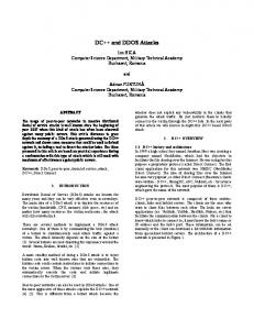
Parameter pkt=packet MarkPacket(pkt) 1.Check if pkt marked. 2.If pkt marked, drop and log pkt if controller ID not present. 3. If pkt not marked, mark packet with controller ID and agent ID. BlockAttackTraffic(pkt) 1. If packet matches Attack Signature drop and log pkt. 2. else MarkPacket(pkt). Fig 4: Agent Mechanism There are two important stages in the implementation of agent mechanism as shown in Fig: 4. The first stage is invoked when the agent receives a command from its controller to mark the traffic to the victim. The agent dynamically applies a filter with the destination address that of the victim and marks the packet with the controller ID and agent ID in the fragment ID field. Packets are marked only by the Ingress agent or by the first agent (in case of incremental deployment) that sees the traffic to the victim. All the fragments and packets that are marked by the attacker are identified and eliminated at this stage (see section II A). The second stage is invoked when the agent receives a command from its controller to prevent the attack traffic to the victim. In this stage, the agent drops all the packets that match the attack signature. All the packets that do not match the attack signature are again marked with the controller ID and the agent ID and are destined to the victim. The main reason for
marking the packets even if it does not match the attack signature is to enable the victim to identify if there are any changes in the attack traffic pattern for it and generate a quick response. III.
EXTENDED MODEL
We extend this model to prevent DoS attacks in multiple ISP domains. Before considering the extension, we discuss some additional assumptions that are being made: •
There exist a strong authentication scheme between the controllers in different domains. We are currently working on the development of such authentication protocols.
•
Communication between the controllers is encrypted. We are currently working on the use of cryptographic techniques for secure communication and key management schemes.
•
The ISPs are willing to cooperate in preventing DDoS attacks.
•
A trust relationship exists representing different domains.
C1
A14
C2
A13
V
controllers
Ci : An : Atn : P : V :
Controller Agent Attack traffic Poor Traffic Victim
A23
A24
ISP1
A11
between
At2
ISP2
A12
At1
A21
A22
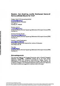
assign unique agent ID’s to its agents and updates the controller in the Victim’s domain with the valid agent ID’s. Now the controller in the Victim’s domain updates its agents with the valid controller IDs in other ISP’s domain and updates the Victim with valid controller IDs and agent IDs for each controller. The controllers in other domains will command their agents to mark the traffic to the Victim. The process is similar to the marking in the Victim’s domain except that the unused bit in the flags field is enabled in this case to indicate that the packets are marked in other ISP’s domain. In Figure 6, the Fragment ID field is used to mark the packets with the controller ID and agent ID, and the unused bit in the flags field is enabled to indicate that the packet is marked in another ISP domain. Enabling the unused flag bit does not have any effect on the current implementation of the Internet [8]. Now the traffic to the Victim is marked in all domains. When the packets marked in other ISP’s domain enters the Victim’s ISP domain, if the unused flag bit is enabled, then the agents in the Victim’s domain can identify that the packets are marked in the other ISP domain. Since the controller in Victim’s domain has already updated its agents on the valid controller IDs, the agent only needs to check for a valid controller ID to pass the packet. If the marked packet does not match the valid controller ID, then the packets are dropped. Now the Victim is in a position to easily identify different attack signatures for each attacking source/agent in different domains. The Victim identifies different attacking signatures based on the agent ID for each controller ID for different domains and updates its controller with this information. The controller retrieves the 32-bit IP address of the controllers in other domains based on the controller ID and transfers the attack signatures for each ISP’s domain. Now prevention starts in the other domain and the prevention process is similar to the prevention in a single ISP domain.
P
Fig 5: Prevention of DDoS Attack in Multiple ISP’s
Each ISP domain is to have a controller. The controller maintains the database of all the agents in its domain and the controllers in the other domain. Whenever there is DDoS attack, the prevention process will initially begin within the Victim’s domain. In this case all the upstream attack traffic is identified at the ingress edge router of the Victim’s ISP domain and prevented at that point. In Figure 5 all the attack traffic originating from say ISP2 is identified and prevented at the agent A13 of ISP1. This would prevent access to the poor traffic P. If the attack persists for a long time or if the Victim requests to prevent the attack upstream, then the prevention can be performed in another ISP domain. Now the controller in the Victim’s domain requests to have a session with the controllers in other ISPs’ domains. A session is established between the controllers after proper authentication between them. Now the controller in the Victim’s domain requests the controllers in other domains to mark the packets destined to the Victim. To avoid overlapping of controller IDs, the controller in the Victim’s domain generates and issues a unique controller ID for every controller. The decision is based upon the number of agents present for each controller. The controllers in each domain
Ver
H.L
ToS
Fragment ID (16-bit) TTL
Protocol
Total Length Flags
Fragment Offset Header Checksum
Source IP Address Destination IP Address
Fig 6: IP Header. Darkened Area used for marking packets Consider the scenario in Figure 7. Let us assume that each ISP has implemented our model and ISP B provides transit for ISP C’s traffic to reach ISP A. If there is a DDoS attack in ISP A’s customer, then the controller in ISP A should also update the controller in ISP B with the controller ID used in ISP C. Further the controller in ISP B should update its agent with the controller ID of ISP C. Otherwise, all the traffic from ISP C will be dropped at the Ingress router/agent of ISP B. Alternatively, the ISP A controller will not have a session with controller in ISP C, so that all the traffic from ISP C will be marked at ISP B’s Ingress agent and prevented at that
format. ISP’s use this stored information to configure their backbone routers, analyze routing policy, and build tools to help in these efforts.
point. So there is a need for the controller in every domain to know about the policies of different ISPs. C1
C3
•
Route Servers (RS): The Route Servers simplify the process of routing. Routing information exchange is done by gathering the routing information from each ISP’s router attached at the network access point (NAP) and by processing the information according to the policies of the ISP. Route Server does not forward packets between ISP routers and are often deployed in pairs at every NAP to provide redundancy and backup. The Route Server can create Routing Information Base for each ISP peer router, which is called a ‘View’. The view is generated in such a way that meets the policy requirements of that particular ISP. Now instead of peering with all other ISP routers at the NAP, each ISP router only needs to peer with the route server to obtain the same routing information.
•
Routing Arbiter Network Operations Center (RA-NOC): The main functions of this RA-NOC include communicating current and correct configuration information to all the Route Servers, monitoring the operations of the route servers, alert operators of any unexpected behavior and gathering operational statistics of the Routing Arbiter.
•
RtConfig: This tool is used to generate low-level router configurations from the high-level policy specifications. For any changes in the policies of an ISP each router has to be updated consistently and any mis-configuration can lead to a severe impact on the routing table. Further there may be many routers within each ISP and each vendor has different syntax and mechanism for configuration. RtConfig supports automatic configuration of routers from multiple vendors according to the specified policies.
C2
ISP A
ISP C ISP B
Fig 7: Special case in Multiple ISP’s The other way to implement our model is by introducing the notion of hierarchy. In this approach each ISP will have a controller. All these controllers will be implemented as agents to other controller, which we call the Master controller. The Master controller can be implemented at an ISP with large network or by grouping few ISP’s. Whenever there is an attack, the victim can contact the controller within its ISP’s domain and the prevention of attack is done only within the ISP domain. If the attack is to be prevented in other ISP domains, the controller in the Victim’s domain will request its Master controller to prevent the attack in other ISP domains. As prevention of attack has already started in the victim’s domain, the controller in the victim’s domain will also update the Master controller with the controller ID used to mark the packets in its domain. Now the Master controller will assign a unique controller ID for the controllers in other ISP’s domain and commands the controllers to prevent the attack. The prevention process is similar to the first approach. We prefer to use the second approach, as there is already an implemented (working) architecture that suits our model (Routing Arbiter) with a little modification. IV.
IMPLEMENTATION OF EXTENDED MODEL
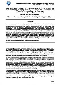
We are currently working on the implementation of our extended model. Our implementation will make use of the Routing Arbiter [16,17,18]. The Routing Arbiter is deployed at the Network Access Point (NAP) where multiple ISPs peer with each other. The Routing Arbiter is developed to simplify the routing process in multiple domains by taking all the policies of the ISP’s into consideration. Our model will be implemented in a hierarchy where the Routing Arbiter is the main controller and the backbone routers at the network access points are the agents for the Routing Arbiter. These agents are the controllers for each ISP, which have their agents within their domains. Figure 8 shows the proposed implementation of our model. The controller for each ISP will be implemented at the Network Access Point (NAP) where different ISP’s routers peer and exchange their routing information. Important components in the Routing Arbiter architecture are described in brief here: •
RADB: This is a logically centralized database of routing information. This is used to generate the Route Server (RS) configuration files. The RADB is part of a distributed set of databases known as the Internet Routing Registry (IRR). IRR is a public repository of announced routes and routing policy in a common
Further there are many tools (which are not shown) that can be used to enhance the functions of Routing Arbiter. For example there are tools that can be used to visualize the effects before committing changes, diagnose routing problems, verification of registered policies, aggregation analysis etc. There are several advantages of implementing the extended model with the Routing Arbiter. For instance, since the Routing Arbiter/ Route server does not forward any IP packets, it is itself protected from DDoS attack. Also it is possible to prevent multiple attacks on multiple victims in multiple domains, as all the policies of each ISP are stored in the RADB. Furthermore, the option of visualization of effects before committing the changes does not affect the global routing table. V.
CONCLUSION
In this paper, we have extended our previous model to prevent DDoS attacks in multiple ISP domains. We have also proposed implementation of model using the Routing Arbiter. Currently we are developing a security architecture for the proposed model and designing secure authentication and access control aspects between the victim, controller and agents.
Routing Arbiter
RADB
RS
RtConfig
A43
A44
A34
ISP4
ISP3
A41
A42
A14
A13
ISP1
A11
A33
C4
C3
C2
C1
A31
A23
A23
ISP2
Network Access Point A12
A32
A21
A22
Fig 8: Implementation of our model with Routing Arbiter
REFERENCES [1] Computer emergency response team. CERT advisory CA-2000-01 denial-of-service developments. http://www.cert.org/advisories/CA-2000-01.html, Jan.2000. [2] Computer emergency response team. CERT advisory CA-1999-17 denial-of-service tools. http://www.cert.org/advisories/CA-1999-17.html. [3] David Moore, Geoffrey M. Voelker and Stefan Savage, “Inferring internet denial -of-service activity,” In proceedings of the 10th USENIX Security Symposium, August 2001. [4] P.Ferguson and D.Senie, “Network ingress filtering: defeating denial of service attacks which employ IP source address spoofing,” RFC 2267, January 1998. [5] SANS institute resources. Egress filtering. February 2000. http://www.sans.org/y2k/egress.htm. [6] Hal Burch and Bill Cheswick, “Tracing anonymous packets to their approximate source,” In proceedings of Usenix LISA, December 2000. [7] Steve Bellovin, “ The ICMP traceback message,” http://www.research.att.com/~smb, 2000. [8] Drew Dean, Matt Franklin and Adam Stubblefield, “ An algebraic approach to IP traceback,” In proceedings of NDSS’01, February 2001. [9] Stefan Savage, David Wetherall, Anna Karlin and Tom Anderson, “Practical network support for IP traceback’” In proceedings of the 2000 ACM SIGCOMM Conference, pages 295-306, August 2000.
[10] D. Song and A.Perrig, “Advanced and authenticated marking schemes for IP traceback,” Technical Report UCB/CSD-00-1107, University of California, Berkeley, June 2000. [11] Robert Stone: “CenterTrack: an IP overlay network for tracking DoS floods,” In proceedings of 9th Usenix Security Symposium, August 2000. [12] Ratul Mahajan, Steven M.Bellovin, Sally Floyd, John Ioannidis, Vern Paxson, and Scott Shenker, “Controlling high bandwidth aggregates in the network,” Draft, February 2001. [13] Udaya Kiran Tupakula, Vijay Varadharajan, “ A practical method to counteract denial of service attacks,” In proceedings of the twenty -fifth Australasian computer science conference (ACSC2003). [14] U.K.Tupakula, V.Varadharajan, “Model and mechanisms for counteracting distributed denial of service attacks,” Technical Report, Macquarie University, 2002. [15] J.Postel : Internet protocol. RFC 791,Sept.1981. [16] D.Estrin, J.Postel, Y.Rekhter, “Routing arbiter architecture,” http://www.isi.edu/div7/ra/Publications. [17] Merit Network Inc, “Route server next generation project,” http://www.rsng.net. [18] USC/ISI, “Brief summary of ISI’s contributions to the routing arbiter effort,” http://www.isi.edu/div7/ra/Publications.