Coupling efficiency of light to surface plasmon polariton for single subwavelength holes in a gold film Anne-Laure Baudrion1,∗ , Fernando de Le´on-P´erez2 , Oussama Mahboub3 , Andreas Hohenau1 , Harald Ditlbacher1 , Francisco J. Garc´ıa-Vidal4 , Jos´e Dintinger3 , Thomas W. Ebbesen3 , Luis Mart´ın-Moreno2 and Joachim R. Krenn1 1 Karl-Franzens
University and Erwin Schr¨odinger Institute for Nanoscale Research, A-8010 Graz, Austria.
2 Departamento
de F´ısica de la Materia Condensada, Facultad de Ciencias-ICMA, Universidad de Zaragoza-CSIC, E-50009 Zaragoza, Spain
3 Laboratoire
de Nanostructures, ISIS, Universit´e Louis Pasteur, F-67000 Strasbourg, France
4 Departamento
de F´ısica Te´orica de la Materia Condensada, Universidad Aut´onoma de Madrid, E-28049 Madrid, Spain
[email protected]
Abstract: The excitation of surface plasmon polaritons (SPP) by focusing a laser beam on single subwavelength holes opened in a thin gold film is studied both experimentally and theoretically. By means of leakage radiation microscopy, quantitative measurements of the light-SPP coupling efficiency are performed for holes with different sizes and shapes. The system is studied theoretically by using a modal expansion method to calculate the fraction of the incident energy which is scattered by the hole into a surface plasmon. We demonstrate that a single subwavelength hole can be used to generate SPP with an efficiency up to 28%. © 2008 Optical Society of America OCIS codes: (240.6680) Optics at surfaces: Surface plasmons; (050.1220) Diffraction and gratings: Apertures
References and links 1. J.-C. Weeber, Y. Lacroute and A. Dereux, ”Optical near-field distributions of surface plasmon waveguide modes,” Phys. Rev. B 68, 115401 (2003). 2. M. U. Gonz´alez, J.-C. Weeber, A.-L. Baudrion, A. Dereux, A. L. Stepanov, J. R. Krenn, E. Devaux and T. W. Ebbesen, ”Design, near-field characterization, and modeling of 45 surface-plasmon Bragg mirrors,” Phys. Rev. B 73, 155416 (2006). 3. A. Hohenau, J. R. Krenn, A. L. Stepanov, A. Drezet, H. Ditlbacher, B. Steinberger, A. Leitner and F. R. Aussenegg, ”Dielectric optical elements for surface plasmons,” Opt. Lett. 30, 893–895 (2005). 4. E. Devaux, T. W. Ebbesen, J.-C. Weeber and A. Dereux, ”Launching and decoupling surface plasmons via microgratings,” Appl. Phys. Lett. 83, 4936–4938 (2003). 5. R. H. Ritchie, E. T. Arakawa, J. J. Cowan and R. N. Hamm, ”Surface-Plasmon Resonance Effect in Grating Diffraction,” Phys. Rev. Lett. 21, 1530–1533 (1968). 6. F. L´opez-Tejeira, S. G. Rodrigo, L. Martin-Moreno, F. J. Garc´ıa-Vidal, E. Devaux, T. W. Ebbesen, J. R. Krenn, I. P. Radko, S. I. Bozhevolnyi, M. U. Gonzalez, J.-C. Weeber and A. Dereux, ”Efficient unidirectional nanoslit couplers for surface plasmons,” Nat. Phys. 3, 324–328 (2007).
#90854 - $15.00 USD
(C) 2008 OSA
Received 18 Dec 2007; revised 4 Feb 2008; accepted 6 Feb 2008; published 28 Feb 2008
3 March 2008 / Vol. 16, No. 5 / OPTICS EXPRESS 3420
7. P. Lalanne and J. P. Hugonin, ”Interaction between optical nano-objects at metallo-dielectric interfaces,” Nat. Phys. 2, 551–556 (2006). 8. H. Ditlbacher, J. R. Krenn, A. Hohenau, A. Leitner and F. R. Aussenegg, ”Efficiency of local light-plasmon coupling,” Appl. Phys. Lett. 83, 3665–3667 (2003). 9. H. Ditlbacher, J. R. Krenn, G. Schider, A. Leitner, F. R. Aussenegg, ”Two-dimensional optics with surface plasmon polaritons,” Appl. Phys. Lett. 81, 1762–1764 (2002). 10. E. Popov, N. Bonod, M. Nevi`ere, H. Rigneault, P.-F. Lenne and P. Chaumet, ”Surface plasmon excitation on a single subwavelength hole in a metallic sheet,” Appl. Opt. 44, 2332–2337 (2005). 11. T. W. Ebbesen, H. J. Lezec, H. F. Ghaemi, T. Thio, and P. A. Wolff, ”Extraordinary optical transmission through sub-wavelength hole arrays,” Nature 391, 667 (1998). 12. A. Drezet, A. Hohenau, A. L. Stepanov, H. Ditlbacher, B. Steinberger, N. Galler, F. R. Aussenegg, A. Leitner and J. R. Krenn, ”How to erase surface plasmon fringes,” Appl. Phys. Lett. 89, 091117 (2006). 13. E. Kretschmann and H. Raether, ”Radiative decay of non-radiative surface plasmons excited by light,” Z. Naturforsch. Teil A 23, 2135–2136 (1963). 14. H. Raether, Surface Plasmons, Springer Tracts in Modern Physics, Vol 111 (Springer, Berlin, 1988). 15. J. Magnes, D. Odera, J. Hartke, M. Fountain, L. Florence and V. Davis, ”Quantitative and Qualitative Study of Gaussian Beam Visualization Techniques,” http://arxiv.org/abs/physics/0605102. 16. B. Hecht, H. Bielefeldt, L. Novotny, Y. Inouye and D. W. Pohl, ”Local Excitation, Scattering, and Interference of Surface Plasmons,” Phys. Rev. Lett. 77, 1889–1892 (1996). 17. A. Vial, A-S. Grimault, D. Mac´ıas, D. Barchiesi, and M.L. de la Chapelle, ” Improved analytical fit of gold dispersion: Application to the modeling of extinction spectra with a finite-difference time-domain method,” Phys. Rev. B 71, 085416 (2005). 18. R. Gordon and A. G. Brolo, ”Increased cut-off wavelength for a subwavelength hole in a real metal,” Opt. Express 13, 1933–1938 (2005). 19. F. J. Garc´ıa-Vidal, L Mart´ın-Moreno, E. Moreno, L. K. S. Kumar, and R. Gordon, ”Transmission of light through a single rectangular hole in a real metal,” Phys. Rev. B 74, 153411 (2006). 20. F. L´opez-Tejeira, F.J. Garc´ıa-Vidal, and L. Mart´ın-Moreno, ”Scattering of surface plasmons by one-dimensional periodic nanoindented surfaces,” Phys. Rev. B 72, 161405 (2005). 21. J. Bravo-Abad, F. J. Garc´ıa-Vidal, and L. Mart´ın-Moreno, ”Resonant Transmission of Light Through Finite Chains of Subwavelength Holes in a Metallic Film,” Phys. Rev. Lett. 93, 227401 (2004). 22. F. de Le´on-P´erez, F. J. Garc´ıa-Vidal, and L. Mart´ın-Moreno, to be published. 23. P. Lalanne, J. P. Hugonin and J. C. Rodier ”Theory of Surface Plasmon Generation at Nanoslit Apertures,” Phys. Rev. Lett. 95, 263902 (2005). 24. C. Genet and T. W. Ebbesen, ”Light in tiny holes,” Nature 445, 39 (2007). 25. C. Sonnichsen, A. C. Duch, G. Steininger, M. Koch, G. von Plessen and J. Feldmann, ”Launching surface plasmons into nanoholes in metal films,” Appl. Phys. Lett. 76, 140–142 (2000). 26. R. Wannemacher, ”Plasmon-supported transmission of light through nanometric holes in metallic thin films,” Opt. Commun. 195, 107–118 (2001).
1.
Introduction
Surface plasmon polaritons (SPP) have attracted increasing attention in the last decades, mainly as these electromagnetic waves propagating at the interface between a metal and a dielectric are spatially confined beyond the diffraction limit. This characteristic is the basis for the development of new plasmonic devices. Many studies have been performed on passive devices like plasmon-guides [1], -mirrors [2] or -lenses [3], but a remaining key point is to develop a highly integrated plasmon source. Various structures such as gratings [4, 5], slits [6, 23, 7], ridges [8] or single defects [9, 10] on a metallic film have been recently investigating for SPP excitation. Most of these previous studies have been restricted to qualitative investigations. However, the quantification of the light-SPP coupling efficiency is of prime interest in the development of SPP-based devices. A quantitative study has been performed for ridges [8] which have displayed a good SPP directionality but a relatively small efficiency. This article reports on the light-SPP coupling efficiency of nanoscale single apertures in a thin metallic film. The first part of this work is devoted to quantitative measurements of this efficiency for single circular or square holes with varying sizes. In the second part, we use a modal expansion method to compute the quantity of the incoming energy which participates to the plasmon excitation. These calculations are compared to the experimental results and the agreement is finally discussed. #90854 - $15.00 USD
(C) 2008 OSA
Received 18 Dec 2007; revised 4 Feb 2008; accepted 6 Feb 2008; published 28 Feb 2008
3 March 2008 / Vol. 16, No. 5 / OPTICS EXPRESS 3421
2.
Measurements
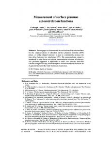
The excitation of SPPs is performed by focusing a cw Titanium-Sapphire laser beam (wavelength tunable between 700 and 950 nm and beam waist of 1.3 µ m) on nanoscale surface features of a 43 nm-thick gold film. The focus of our interest were surface features such as circular and square holes opened by focused ion beam (FIB) etching in the whole depth of the gold film [11]. The size of those defects (circle diameter or square side length) varies between 100 nm and 450 nm. The light-SPP coupling efficiency is measured by means of leakage radiation microscopy (Fig. 1). During the propagation of the SPP at the air-metal interface, it is damped
Beam-Blocker
L3
L4
Camera CCD
BS
O2
O1
L1
F1
L2 S1 F2
L5
L6
F3
Leakage radiation
Powermeter Fig. 1. (color online) Scheme of the leakage radiation microscope. SPPs are excited by laser light focused by the microscope objective O1 (50×, numerical aperture = 0.7) onto the sample’s features (inset). The leakage radiation emitted through the glass substrate is collected by the immersion microscope objective O2 (63×, numerical aperture = 1.25). The Fourier plane of this objective (F1 ) is imaged, through a beam splitter, both on a chargecoupled-device (CCD) camera and on the detector of a powermeter. A beam-blocker is placed in the Fourier plane F2 to stop the directly transmitted laser beam. The lens L4 can be removed to image the sample plane on the CCD camera.
by radiative loss through the substrate. This so-called leakage radiation (LR) is emitted at an angle θLR defined by kSPP = nk0 sin θLR , where kSPP and k0 correspond respectively to the wave vectors of the SPP and the LR light in free space, and n is the refractive index of the glass substrate. The LR is collected by an immersion oil objective (63×, numerical aperture = 1.25) and is projected by the lens L1 into the image plane S1 (see Fig. 1). In addition, the Fourier plane (or back focal plane) F1 contained within the immersion objective is also projected by the lens L1 onto the plane F2 where the light intensity distribution can be selectively blocked [12]. In combination with a beam-splitter, the lenses L2 , L3 and L4 allow us to image either the sample plane or the Fourier plane (depending on the presence of the last lens L4 ) onto a charge-coupled-device (CCD) camera, while the lenses L2 , L5 and L6 project the Fourier plane onto the detector of a powermeter. The intensity distribution of the Fourier plane of an imaging optic represents the different wave vector components of the image. For a SPP propagating in all directions at the gold-air interface, the corresponding leakage radiation is distributed over a cone with its axis perpendicular to the substrate plane and an opening angle of θLR . In this case, the Fourier plane image is a bright circle. In case the SPP presents an angular intensity distribu#90854 - $15.00 USD
(C) 2008 OSA
Received 18 Dec 2007; revised 4 Feb 2008; accepted 6 Feb 2008; published 28 Feb 2008
3 March 2008 / Vol. 16, No. 5 / OPTICS EXPRESS 3422
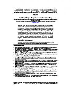
tion at the air-metal interface, the Fourier plane reflects then this particular angular distribution. The thickness of the gold film has been specifically chosen to perform the coupling efficiency measurements at an incident laser wavelength of 800 nm. Indeed, for this specific wavelength, the reflectivity of the exciting laser beam in Kretschmann configuration [13] is virtually equal to zero for a thickness of the gold layer of 43 nm. As pointed out in Ref. [14], for this case, the damping due to LR emission and the internal ohmic damping of a SPP propagating at the air-metal interface are identical, assuming there is no other damping channel. Thus half the SPP intensity is emitted into LR. For a laser power Pin , the light-SPP coupling efficiency E can then be straightforwardly calculated: 2PLR PSPP = , (1) E= Pin Pin where PSPP is the power of the SPP propagating at the air-gold interface and PLR is the power of the corresponding leakage radiation. With our set-up, we measure only half the LR emitted through the substrate, due to the presence of the beam-splitter BS in the optical set-up (Fig. 1). As, in addition, the LR coming from the sample is attenuated by the optical elements, the laser beam power Pin , focused on a bare glass substrate, has been measured at the same location as the LR, i.e., after these optical elements. In this way, the attenuation coming from the set-up is taken into account for both leakage and incident power to calculate the coupling efficiency. Moreover, this coupling efficiency has been normalized with respect to the power incident onto the hole area. We have measured the two-dimensional focus profile of our laser beam by the knife-edge method [15] and then computed the three-dimensional intensity profile of the laser focus. The numerical integration of this profile over the hole area gave us the fraction of incident power which indeed contributes to the light-SPP coupling. This normalized value of Pin allows us to calculate the normalized coupling efficiency. As an example we discuss now the measurements for a circular hole with a diameter of 400 nm (Fig. 2(a)). Figure 2(b) shows the CCD camera image recorded in the Fourier plane as the laser is focused onto the hole. It is worth to note that the value given by the powermeter corresponds to the integration value of the total image. The image displays a ring delimited by the numerical aperture of the immersion objective (outside boundary) and by the diameter of the beam-blocker (inside boundary). The bright crescents which appear in the middle of the ring reflect the intensity distribution of the SPP propagating along the air-gold interface. As we use a polarized laser beam in the direction indicated by the white arrows in Fig. 2(a), the angular distribution of the SPP launched by a circular hole obviously does not form a uniform circle but a circle modulated by the characteristic cos2 (Θ) angular distribution [16], where Θ is the polar angle between the polarization axis of the laser and the direction of the observation point. The LR is however superimposed on a scattered light background. To retrieve the LR contribution we analyze an intensity cross-cut along the polarization axis, indicated by the white dashed line in Fig. 2(b). The intensity value separating the SPP signal from the background signal can be clearly identified (Fig. 2(c)). We now chose the intensity data above, respectively below, the limit value to separate the plasmon signal (Fig. 2(d)) from the background signal (Fig. 2(e)). By integrating the intensity over both images, we can compare both signals and conclude that the LR corresponds approximately to 30% of the total power measured. This comparison has been performed for various circular holes with different diameters from 200 to 450 nm and the same ratio of 30 ± 3% has been obtained. For a circular hole with a diameter of 100nm, the camera images are not contrasted enough to determine precisely the limit between plasmon and background signals and an incoherent value of 22 ± 10% is obtained. Consequently, an attenuation of 30% has been applied to each measured LR power to calculate the coupling efficiency. Figure 3 shows the normalized coupling efficiency obtained as a function of the hole size for circular and square holes. We observe that the normalized coupling efficiency
#90854 - $15.00 USD
(C) 2008 OSA
Received 18 Dec 2007; revised 4 Feb 2008; accepted 6 Feb 2008; published 28 Feb 2008
3 March 2008 / Vol. 16, No. 5 / OPTICS EXPRESS 3423
p
200nm
(b)
(a)
(c)
(e)
(d)
30
30
25 20 15 10 5 0
(a) 0
100
200
300
400
Circle diameter (nm)
500
25 efficiency (%)
Normalized coupling
efficiency (%)
Normalized coupling
Fig. 2. (a) Scanning electron microscope image of a circular hole with a diameter of 400 nm opened in a 43 nm-thick-gold film. The white double arrow shows the direction of the polarization of the exciting laser beam. (b) Image of the Fourier plane recorded by the CCD camera for the hole shown in (a). The beam-blocker is used to suppress the transmitted laser beam. (c) Cross-cut recorded along the white dashed line in (b) showing the value separating the plasmon signal from the background (represented by a dashed line in (c)). (d) and (e) Same images as (b) obtained by numerically separating the intensity data above and below the value obtained in (c). The image (d) shows the plasmon signal and the image (e) shows the background signal.
20 15 10 5 0
(b) 0
100
200
300
400
500
Square side (nm)
Fig. 3. Normalized coupling efficiency measured as a function of the circle diameter (a) and the square side length (b) of the hole. Both curves have been normalized by taking into account the fraction of power incident on the hole area. The error bars correspond to the spreading of the values during different measurement runs. The lines are mere guides to the eye.
#90854 - $15.00 USD
(C) 2008 OSA
Received 18 Dec 2007; revised 4 Feb 2008; accepted 6 Feb 2008; published 28 Feb 2008
3 March 2008 / Vol. 16, No. 5 / OPTICS EXPRESS 3424
displays similar dependencies on the hole size for circular and square holes. For sizes below about 200 nm, the coupling efficiency increases rapidly to reach a maximum of about 23 ± 4% for circular holes and about 28 ± 1% for square holes. For increasing hole size, the coupling efficiency decreases slowly to reach a constant value of about 18 ± 4% and 16.0 ± 0.5%, for circular and square holes, respectively. The error bars included in the graphs denote the spread in the measured values. The difference in the size of the error bars, observed between square and circular holes, is probably due to variations in the structure of the hole’s edges, which are more pronounced for circular holes than for square holes as analyzed by scanning electron microscopy. As a reference, a 250 nm wide slit has also been investigated and a normalized coupling efficiency of about 9% has been found. It should be noted that the absolute coupling efficiency (i.e., without normalization to the hole-area) for the slit is about 5%, which is in good agreement with the value obtained for a single ridge in reference [8]. It is worth to note that our measurements require a thin metal film. In this case, the SPP of interest, sustained by the gold-air interface, can couple to the SPP sustained by the gold-glass interface. As the leakage radiation intensity is reduced by the use of a thicker film, the light-SPP coupling efficiency can be increased as a consequence. For a given hole size we have then investigated the behavior of the light-SPP coupling efficiency as a function of the incident wavelength. Therefore, the leakage power has been recorded with wavelengths ranging from 730 to 930 nm. In this case, however, the expression of the coupling efficiency given by the Eq. 1 has to be modified. Indeed, the ohmic losses and the radiative losses of an SPP propagating in the air-metal interface of a 43 nm thick gold film deposited on a glass substrate are wavelength-dependant (Fig. 4(a)). From these curves, we can deduce, for each wavelength, the ratio between radiative and ohmic damping, which corresponds to the ratio between the powers dissipated due to leakage radiation PLR and due to ohmic losses PΩ during the propagation of the SPP. The coupling efficiency can then be calculated from the following expression: Ω ) PLR (1 + PPLR PLR + PΩ PSPP = = (2) E= Pin Pin Pin The normalized coupling efficiency measured for a circular hole with a diameter of 350 nm as a function of the incident wavelength is displayed in Fig. 4(b). We can observe that for a wavelength increasing from 730 to 930 nm the normalized coupling efficiency slowly decreases from about 25% to 12%. Moreover, for an incident wavelength of 800 nm the coupling efficiency is about 17%, which corresponds to the value measured previously for a circular hole with the same size. 3.
Theory
In order to theoretically understand the experimentally observed behavior of the coupling efficiency, we have solved Maxwell’s equations with help of a modal expansion formalism. The system used is composed of a glass substrate covered with a 43 nm-thick gold film in which a circular or a square hole has been opened. We assume a p-polarized Hermite-Gaussian beam, with a waist of 1.3 µ m, impinging perpendicularly to the metal surface, from the air-side. The electromagnetic fields in both the air and the glass regions are conveniently expanded in terms of s- and p-polarized plane waves, whereas inside the hole the fields are written as linear combinations of TE and TM waveguide modes, with either cylindrical or rectangular symmetry. We used the Drude-Lorentz model reported in Ref. [17] for the gold wavelength-dependent dielectric function. Inside the hole, a system of linear equations for the expansion coefficients of the electromagnetic field is set up by matching the parallel components of these fields at the two interfaces assuming surface impedance boundary conditions (SIBC). Moreover, we assume perfect conductor boundary conditions at the lateral walls of the hole, and the effective size of #90854 - $15.00 USD
(C) 2008 OSA
Received 18 Dec 2007; revised 4 Feb 2008; accepted 6 Feb 2008; published 28 Feb 2008
3 March 2008 / Vol. 16, No. 5 / OPTICS EXPRESS 3425
35
D
amping (a.u.)
Ohmic losses
30
Radiative losses
20 10
(a)
0 700
750
800
850
Wavelength (nm)
900
30 efficiency (%)
Normalized coupling
40
25 20 15 10 5
(b)
0 700
750
800
850
900
950
Wavelength (nm)
Fig. 4. (a) Radiative and ohmic losses of a SPP propagating in the air-gold interface of a 44 nm thick gold film calculated as a function of the incident wavelength. This calculation is based on the equations 2.22 and 2.23 of the reference [14]. The thickness of 44 nm has been chosen in order to have an equality between radiative and ohmic losses at a wavelength of 800nm. (b) Normalized coupling efficiency measured as a function of the incident wavelength for a circular hole with a diameter of 350 nm.
the hole is enlarged by a skin depth, to consider the penetration of the fields in the metal. After solving the set of linear equations, the electromagnetic fields in the whole space are computed straightforwardly with help of the obtained expansion coefficients. It is worth to note that the propagation constant inside the hole is calculated by considering a waveguide with the considered cross section opened in a real metal. Moreover, for square holes, we base on the results of references [18, 19] to use a realistic value for the propagation constant of the fundamental mode inside the hole, which is obtained by employing an effective index theory. We note that the calculations were not done within the single mode approximation and a full multimode expansion was employed using as many modes as needed to achieve convergence. Additional details of the calculations can be found in Refs. [6, 20, 21, 22]. Indeed, the present approach is a generalization to the case of 3D defects in metal films of the model recently proposed to treat one-dimensional indentations [6, 20, 23]. Once knowing the electromagnetic fields in the different regions of the system, we calculate the light-SPP coupling efficiency by calculating the fraction of the incident energy which has been scattered into SPP. By integrating the Poynting vector of each field, we reach the different energy density fluxes, which correspond to the different coupling efficiencies. We assume that the incident energy can be either radiated into other propagating light waves or scattered into SPP at each interface of the metal layer. In what follows we show that these are the relevant scattering channels for the parameter space studied in this paper. In order to compute the part of the incident energy which is scattered into SPP at the air-metal interface, we integrate the Poynting vector along the lateral surface of the imaginary cylinder shown in the inset of Fig. 5. The fraction of the incoming energy scattered into radiative waves can be calculated by using the top and bottom faces of this virtual cylinder. Moreover, all these energies have been normalized to the incident energy per hole unit area. The SPP field is obtained through the plasmon-pole contribution of the propagator, which gives the total electromagnetic field in terms of the modal amplitudes of the field at the hole. → − → − Simple analytical expressions for both the electric, E spp , and the magnetic H spp fields are obtained and it is straightforward to compute the normalized coupling efficiency by integrating the projection of the Poynting vector. It is worth to recall that in our case, the mean free #90854 - $15.00 USD
(C) 2008 OSA
Received 18 Dec 2007; revised 4 Feb 2008; accepted 6 Feb 2008; published 28 Feb 2008
3 March 2008 / Vol. 16, No. 5 / OPTICS EXPRESS 3426
Normalized coupling efficiency [%]
Normalized coupling efficiency [%]
path of a SPP excited on the metal surface is at least two orders of magnitude larger than the size of the defects. Therefore taking into account ohmic losses is not essential. In this lossless case, the SPP energy flux is independent of the observation point R in the metal plane and the width of the virtual cylinder is not important. Moreover, given the plasmonic character of the fields, the SPP energy decays exponentially along the z direction, and consequently the height of the cylinder (or the upper bound of the integral) can be taken as infinite. For an absorbing metal, the SPP energy decays, as function of the observation point R in the metal plane, like σspp exp[−2Im(kp)R], where kp is the in-plane SPP wavevector. We characterize the plasmon coupling efficiency by the energy scattered into the plasmon channel, i.e. by σspp , the R-dependence following from the evolution of the surface plasmon in the plane. We recall that under SIBC is neglected the plasmon tunneling between the two metal surfaces. It is also assumed that the fraction of the energy flowing in the metal is small. However, in what follows, we check the validity our model after these approximations. In fact, energy conservation is fulfilled for the lossless case, and those results are consistent with these for the lossy case. Figure 5 shows the normalized-to-area light-SPP coupling efficiency obtained for circular and square holes as a function of their size for a given wavelength of 800 nm. The lossless case is represented by solid lines whereas the dashed lines have been obtained by taking into account the absorption of the metal. We can note that the difference between both cases is less than 1%. The calculations rendered in Fig. 5(a) show that the maximum computed value for the light-
(a)
15
illumination
10
SPP 5
radiative waves 0 100
200
300
400
Circle diameter [nm]
500
(b)
25 20 15 10 5 0 100
200
300
400
500
Square side [nm]
Fig. 5. (color online) Normalized-to-area coupling efficiency computed as a function of the circle diameter (a) and the square side length (b) at an incident wavelength of 800nm. The solid red curves represent calculations neglecting the absorption of the metal while for the black dashed lines losses are taken into account. The virtual cylinder used for this computation is schematically represented in the inset as well as the different energy density fluxes J.
SPP coupling efficiency (about 16%) is found for a diameter of about 300 nm. In the case of square holes (Fig. 5(b)), a peak in the coupling efficiency is more clearly developed than in the circular hole case, with a maximum value of 26% computed for holes of 200 nm side, showing an excellent agreement with the experimental value of 28 ± 1% (Fig. 3(b)). For the circular holes, both the position and the value of the maximum coupling efficiency are slightly different when comparing the experimental and the theoretical results. The position of the maximum is found to be for a diameter of 200 nm in the first case where it is found to be at 300 nm for the second one. Moreover a difference of 7 ± 4% is found between the maximum values. From the computational point of view, we suggest that these differences come from the consideration #90854 - $15.00 USD
(C) 2008 OSA
Received 18 Dec 2007; revised 4 Feb 2008; accepted 6 Feb 2008; published 28 Feb 2008
3 March 2008 / Vol. 16, No. 5 / OPTICS EXPRESS 3427
150
(a) 100
50
air hole glass
0
Plasmonic coupling efficiency [%]
Radiative coupling efficiency [%]
of an isotropic penetration of the electromagnetic field in the lateral walls of the circular hole. Indeed, during our procedure, we enlarge isotropically the hole diameter by a skin depth. The analogy with the case of square holes [19] suggests that an effective elliptical shape would be more appropriate. In this work, no attempt to quantify this effect has been made, as it would greatly complicate the calculations. From the experimental point of view, these differences can be due to the geometrical deviations from the assumed shape of the holes in the experimental samples. This point is corroborated by scanning electron microscopy which identified small defects occurring mainly on small holes. Moreover, the experimental coupling efficiency can be over-evaluated since some possible radiative contribution, scattered by the hole with an angle sufficient to pass the beam-blocker, are added to the plasmon signal measured by the powermeter. As a reference, we calculate now the light-SPP coupling efficiency for a slit with a width of 250 nm. For a incident wavelength of 800 nm, this normalized coupling efficiency is about 13% whereas, with the experimental measurements, we have found 9%. Knowing that the spreading of the values during the measurements gives an error bar of about 4%, this unique experimental value is probably underestimated. As for the experimental case, we now study the behavior of the coupling efficiency as a function of the incident wavelength. For this purpose, we assume a circular hole with a diameter of 350 nm. Figure 6 shows the coupling efficiencies of the incident light with the different possible waves scattered by this hole, as a function of the incident wavelength. The coupling efficiency between the incoming light and the radiative waves is shown in Fig. 6(a) and the light-SPP coupling efficiency is shown in Fig. 6(b). For each case, we precise the part of the system (glass, air or the hole) in which the wave propagates. For example, the green curve on
40
(b) 30 20 10
air-gold glass-gold
0 800
1000
1200
Wavelength [nm]
1400
800
1000
1200
1400
Wavelength [nm]
Fig. 6. (color online) Normalized-to-area coupling efficiency of light to radiative waves (a) and to SPP (b) for a circular hole with a diameter of 350 nm, as a function of the incident wavelength. The solid curves represent calculations neglecting the absorption of the metal while for the dashed lines losses are taken into account.
Fig. 6(a) characterizes the extraordinary optical transmission of the incident light trough the hole. It has been extensively studied both from the theoretical and the experimental point of view [11, 19, 24, 25, 26] and shows a strongly enhanced transmission of light through the hole. Moreover we can observe that the coupling of the incident light with the SPP propagating at the glass side of the metal layer (pink curve in fig. 6 (b)) presents a broad resonant peak similar to what we observe for the coupling with radiated waves. The physical origin of the resonant peak is the same for radiative and plasmonic waves. It appears near the cutoff of the principal waveguide mode in the hole and it is red-shifted for increasing hole dimension [19]. We observe #90854 - $15.00 USD
(C) 2008 OSA
Received 18 Dec 2007; revised 4 Feb 2008; accepted 6 Feb 2008; published 28 Feb 2008
3 March 2008 / Vol. 16, No. 5 / OPTICS EXPRESS 3428
that the behavior of the light-SPP coupling efficiency, at the air side of the gold film (black curve on Fig. 6(b)), between 700 and 900 nm qualitatively recovers to the experimental wavelength dependency of the light-SPP coupling efficiency shown in Fig. 4(b). The theoretical coupling efficiency decreases from about 17% to 14% whereas the experimental efficiency decreases from 25 to 12%. We can even note that for a wavelength of 800 nm, the theoretical value of about 15% is almost similar to the experimental one (17%). In conclusion, we have compared experimental measurements of the light-SPP coupling efficiency for single holes opened in a gold thin film with the results of computations based on a modal expansion method. In both studies, the light-SPP coupling efficiency is maximum for square holes with a side of 200 nm. Moreover, we have shown that a single hole is efficient to launch a surface plasmon polariton and we have quantified this coupling efficiency for different hole sizes and shapes. In the context of the conception of highly integrated plasmonic devices, this work can suggest to use single holes to perform an efficient subwavelength SPP source.
Acknowledgments This work was supported by the European Network of Excellence (NoE) Plasmo-Nano-Devices (FP6-2002-IST-1-507879). The authors acknowledge Frank D. Reil, Daniel Koller, Fernando L´opez-Tejeira and Sergio G. Rodrigo for fruitful discussions.
#90854 - $15.00 USD
(C) 2008 OSA
Received 18 Dec 2007; revised 4 Feb 2008; accepted 6 Feb 2008; published 28 Feb 2008
3 March 2008 / Vol. 16, No. 5 / OPTICS EXPRESS 3429