arXiv:cond-mat/9804279v1 [cond-mat.mtrl-sci] 24 Apr 1998. Crack propagation in quasicrystals. R. Mikulla1, J. Stadler1, F. Krul1, H.-R. Trebin1 and P.
Crack propagation in quasicrystals R. Mikulla1 , J. Stadler1 , F. Krul1 , H.-R. Trebin1 and P. Gumbsch2 1
arXiv:cond-mat/9804279v1 [cond-mat.mtrl-sci] 24 Apr 1998
2
Institut f¨ ur Theoretische und Angewandte Physik der Universit¨ at Stuttgart, Pfaffenwaldring 57, D-70550 Stuttgart, Germany Max-Planck-Institut f¨ ur Metallforschung, Seestr. 92, 70174 Stuttgart, Germany
Crack propagation is studied in a two dimensional decagonal model quasicrystal. The simulations reveal the dominating role of highly coordinated atomic environments as structure intrinsic obstacles for both dislocation motion and crack propagation. For certain overloads, these obstacles and the quasiperiodic nature of the crystal result in a specific crack propagation mechanism: The crack tip emits a dislocation followed by a phason wall, along which the material opens up.
crucial element in the brittle fracture mechanism at low temperature. Furthermore, we identify atomic clusters, inherent to the quasicrystalline structure, as obstacles and scattering centers for the brittle crack. The study of a strongly nonlinear process like dynamical fracture in a complex material requires simplifications. First we consider a two dimensional system (2D) to evade the analysis of a three dimensional crack front. Secondly we simulate a perfectly ordered quasicystalline representative of the binary tiling system [9], derived from the T¨ ubingen triangle tiling (TTT) [11]. A large atom (L) is placed at each vertex and a small atom (S) into the center of each large triangle of the original tiling. When the centers of neighboring atoms of different type are connected, one obtains a rhombic tiling, which we denote as “bond representation” of the direct “atom representation”. Qualitatively our model shares central properties with structure models for real quasicrystals, which are (1) a decagonal diffraction pattern inherited from the TTT [11] and (2) a hierarchical structure of clusters. These are built by a first shell of small atoms and a second shell of large atoms surrounding a central large atom (Fig. 1), and can be considered as 2D versions of Mackay clusters that are significant for many real quasicrystals. Furthermore, assemblies of such clusters form super clusters and so on. The smallest clusters are situated on five families of parallel lines, mutually rotated by 36◦ , with a small and a large separation within each family, arranged in a Fibonacci sequence (Fig. 2). The atoms interact with Lennard-Jones potentials truncated at 2.5 r0 . The bond lengths are chosen to be the geometrical ones [9]. The unit of length in our simulation r0 = rLS is given by the length of the LS bond. The bond energies are ε0 = εLS and εLL = εSS = 0.5ε0 to avoid phase separation. Allp masses are set to 1. The unit of time is therefore t0 = r0 m/ε0 . Due to their high coordination the decagonal clusters become the tightest bound structural units of the quasicrystal model for all choices of εLL and εSS smaller than one. Preferred cleavage planes of the 2D model quasicrystal, i.e. the “easy lines” for fracture, are those in between the large separation of the parallel lines connecting the clusters, because a crack can follow these lines without cutting the tightly bound ten-rings. The surface ener-
Quasicrystals are characterized by an unusual structure: They are orientationally ordered, but with noncrystallographic, e.g., five- or eightfold symmetry axes [1]. Their translational order is not periodic, as in conventional crystals, but quasiperiodic. In the last few years it has become possible to measure physical properties of quasicrystals, such as mass and heat transport, plasticity, and fracture, since high–quality, thermodynamically stable quasicrystals could be grown in millimeter sizes [2]. Because of the peculiar structure, quasicrystals open new possibilities for studying structure–property relations. The mechanical behavior of a solid, in particular, is strongly influenced by structure, because it is mainly governed by defects, which are related to the order. Several studies of the standard icosahedral quasicrystalline alloys AlMnPd and AlCuFe have disclosed that the samples are brittle and hard at room temperature [3], but become ductile at about 80% of the melting temperature, and then can be deformed up to 30% without hardening [4]. Concerning ductility it has been confirmed both by transmission electron microscopy [5] and by computer simulations [6], that motion of dislocations is the mechanism of plastic deformation in quasicrystals. The existence of dislocations in quasicrystals is due to the fact that quasiperiodic structures can be considered as irrational cuts through a higher dimensional periodic crystal [7]. Hence the Burgers vector of a dislocation also is of higher dimension, with a component in physical space and a component in the complementary orthogonal space. The dislocation is described by a “phonon”-like displacement field u(x) and a “phason”-like displacement field w(x), whose contour integrals yield b|| and b⊥ , respectively. Molecular dynamics simulations of a sheared quasicrystal have revealed that close to the melting temperature the phason field is spread out around the dislocation core, whereas at low temperatures it is confined to a plane extending from and being bound by the dislocation line [6,8]. The phase of the quasicrystal is differing by b⊥ at the two sides of this wall, which therefore is denoted as “phason-wall”. In this article we demonstrate – by employing atomistic simulations of fracture processes – that phason walls, being a consequence of the quasiperiodic structure, are a 1
left a phason wall in its wake. This phason wall carries some interface energy, and hence the cohesive strength of the material is reduced at this wall. After some time of strain build-up the crack begins to open along the phason wall (Fig. 4, bottom). It immediately regains its initial propagation velocity until the next obstacle is met. Due to the tightly bound complete ten-rings, the cleavage surface roughness is about 10 r0 . At intermediate loads, between 1.3% and 1.5% strain, a regime of steady crack propagation is observed. The crack tip proceeds with almost uniform velocity, but the appearance of the cleavage plane is unchanged. The dislocation-emission–phason-wall cleavage mechanism is still operates but without stopping the propagating crack. At even higher overloads (≥ 1.5% strain) we observe an onset of crack tip instabilities, which create defects that are not bound to the crack tip. At a strain of 1.5% (Fig. 5) we observe dislocation emission at an angle of 72◦ , which reduces (due to shielding) the load on the crack tip. Arrested by an obstacle, the dislocation moves back and annihilates at the fracture surface after the crack tip has propagated further. Such a process, so–called “virtual dislocation emission”, was first proposed by Brede and Haasen to explain their fracture experiments in silicon [16]. At a load of 1.7% the crack bifurcates and stops. In quasicrystals as in periodic crystals, we find a minimal velocity for brittle crack propagation of 14% of the shear wave velocity vT at low loads. This suggests that there exists a lower band of forbidden crack velocities [17,18]. With rising load, the crack tip speed increases to about 35% of vT . This value is again similar to the maximum crack tip speed in periodic crystals [19]. The lower than expected upper crack velocity, which linear elasticity theory would place at the Rayleigh wave velocity [21] (vRayleigh ≈ 0.9 vT ), may be explained with the non-linearity of the atomic interaction, which has been shown to drastically reduce crack tip velocities in periodic crystals [19,20]. At high loads the upper limit on the crack velocity is determined by the onset of crack tip instabilities: (virtual) dislocation emission and crack branching. It seems likely that the instability is driven by a critical overload or a critical accumulation of specific shear waves. While the crack tip velocity is of similar magnitude in quasicrystals and periodic crystals, the crack propagation mode differs significantly. At small overloads an intermittent crack propagation mode occurs, during which the average crack velocity can be low but microscopically separated into distinct propagation and arrest periods. The fracture surfaces are rough, governed by cluster inhomogeneities. Intermittency and roughness can both be attributed to the novel dislocation-emission–phason-wall fracture mechanism. At comparable external loads the brittle fracture of perfect periodic crystals is characterized by steady crack propagation along well defined flat and smooth cleav-
gies [12] of different crystallographically equivalent, but structurally distinct lines (1-4 in Fig. 2) are lowest for those between the widely spaced ten-rings (3,4 in Fig. 2), namely 1.9 ε0 /r0 as compared to 2.3 ε0 /r0 for the other surfaces studied here (1,2,5 in Fig. 2). Furthermore, they also have the lowest “unstable stacking fault energy”, i.e. increase in energy when the two halfs are shifted relative to each other. Hence these lines are also preferred for dislocation motion [13]. When a dislocation is gliding through a quasicrystal, leaving a phason wall behind, it creates an even more preferred cleavage line, since the phason wall is characterized by a positive defect energy. For the shortest Burgers vector the cleavage energy along the phason wall can be reduced by an additional 0.3 ε0 /r0 [13]. The fracture simulations are performed on a rectangular slab of approximately 250 000 atoms, 250 r0 high and 1.000 r0 wide. The slab is uniformly strained by an amount ∆ normal to the long axis, and in the outermost layer of width 3r0 all atoms are held fixed at these positions. A precrack of length 200r0 is inserted from one side along an easy line by cutting the bonds and relaxing the sample. For the relaxation the externally applied homogeneous strain is fixed at the Griffith value, at which the strain energy per unit length just equals twice the surface energy. The resulting displacement field then is scaled linearly above the critical dilation where the crack tip starts moving. The evolution of the system is followed by standard molecular dynamics (MD) technique where the atoms obey Newtonian equations of motion. The system was started at an initial temperature of T=10−6 Tmelt . The IMD molecular dynamics package was used [14]. During crack propagation, the crack tip bonds are broken and the strain energy above the surface energy (the overload) is released in the form of acoustic emission or dislocation generation. To avoid heating of the slab and phonon reflections from the boundaries an elliptical stadium is created outside which the waves are damped gradually by a ramped friction term in the equations of motion [15]. For the phason-free precracked sample the critical strain is ǫc =1.12%. Straight brittle cleavage along the easy line occurred only very close to this value and for short segments. In all other cases a rough surface is created. The propagating crack is monitored and its current position is plotted versus time for three different loads in Fig. 3. Depending on the load level one can distinguish three different fracture regimes. An intermittent propagation regime is found at low load levels. For example, at a strain of 1.131% the crack proceeds with constant velocity along an easy fracture line until it hits an obstacle (Fig. 4, top), which can be a complete or an incomplete ten-ring. It then stops and emits a dislocation along one of the easy planes inclined by 36◦ , along which the shear stress is high. The dislocation moves away from the crack tip until it is stopped itself by an obstacle(Fig. 4, middle), whereupon the entire configuration rests for some time. The dislocation has 2
age planes [18]. In comparison to periodic crystals, two specific structural components of the quasicrystal are important to explain the observed behaviour. Firstly, the role of the ten-rings as tightly bound clusters which act as structure intrinsic obstacles to both dislocations and cracks is obvious. At low overloads the clusters may temporarily arrest the crack, and even at high overloads and high crack tip speeds, the clusters act as scattering centers for the cracks.
[1] Ch. Janot, “Quasicrystals: A Primer”, Clarendon Press 1994, Oxford. [2] A.P. Tsai in New Horizons in Quasicrystals: Research and Applications, edited by A.I. Goldman, D.J. Sordelet, P.A. Thiel and J.M. Dubois (World Scientific 1996) p. 1. [3] S. Takeuchi, H. Iwanaga and T. Shibuya, Jpn. J. Appl. Phys. 30 (1991) 561. [4] S. Takeuchi and T. Hashimoto, Jpn. J. Appl. Phys. 32 (1993) 2063. [5] M. Wollgarten, M. Beyes, K. Urban, H. Liebertz and U. K¨ oster, Phys. Rev. Lett. 71 (1993) 549. [6] R. Mikulla, J. Roth and H.-R. Trebin, Phil. Mag. B 71 (1995) 981. [7] J. Bohsung and H.-R. Trebin, in: “Aperiodicity and Order” Vol. 2, ed. M.J. Jari´c, Academic Press Inc., (1989) 183 [8] R. Mikulla, J. Roth and H.-R. Trebin, in: Proc. of the 5th Int. Conference on Quasicrystals, eds. C. Janot and R. Mosseri, World Scientific 1995, p. 297. [9] Deconal binary tilings(BT) [10] are mixtures of two species of particles where the bond lengths fulfill the requirement that five particles of type A surround one B– particle and ten B–particles sourround one A–particle. Provided with Lennard–Jones type potentials glassy, crystalline, perfect quasicrystalline and random tiling quasicrystalline phases are possible. The perfectly orderd quasicystalline phases like the BT derived from the TTT is strictly meta stable but at modest temperatures mechanicly stable over time scales accessible with MD simulations. [10] F. Lan¸con and L. Billard in Lectures on Quasicrystals ed. by F. Hippert and D. Gratias, les editions de physique, Les Ulis (1994) 265. [11] M. Baake, P. Kramer, M. Schlottmann and D. Zeitler, Int. J. Mod. Phys. B 4(15/16) (1990) 2217. [12] Because of the lack of periodicity, the surface energy of the quasicrystal must be calculated on finite samples. To minimize sampling errors, the surface energy is determined as the average energy difference per unit length between an intact and an (artificially) cleaved quasicrystal for several parts of the structure with different length. [13] R. Mikulla, P. Gumbsch and H.-R. Trebin, condmat/9708102. [14] J. Stadler, R. Mikulla and H.-R. Trebin, Int. J. Mod. Phys. C 8 (1997) 1131. [15] B.L. Holian and R. Ravelo, Phys. Rev. B 51 (1995) 11275. [16] M. Brede and P. Haasen, Acta metall. 36 (1988) 2003. [17] M. Marder and S. Gross, J. Mech. Phys. Solids 43 (1995) 1. [18] P. Gumbsch, S.J. Zhou and B.L. Holian, Phys. Rev. B 55 (1997) 3445. [19] P. Gumbsch, Z. Metallkd. 87 (1996) 341. [20] B.L. Holian, R. Blumenfeld and P. Gumbsch, Phys. Rev. Lett. 78 (1997) 78. [21] L.B. Freund, “Dynamical Fracture Mechanics”, Cambridge University Press 1990, New York. [22] R. Thomson, in Solid State Physics Vol. 39, edited by H. Ehrenreich and D. Turnbull, Academic Press 1986, New York, pp. 1–129.
In perfect agreement with a previous study of dislocation mobility in quasicrystals [13], we find here that the clusters also act as obstacles to dislocation motion. As a consequence, dislocations that have been nucleated at the crack tip cannot get farther away than the next sufficiently strong obstacle. Since the interaction of the crack tip and the dislocation produces a driving force on the dislocation which decreases with distance from the crack tip [22], the strength of a cluster, measured as the capability to arrest the dislocation, increases with distance. Strong local structural variations, which are a characteristic of the quasicrystalline structure, are therefore very efficient in blocking dislocation motion and tend to keep dislocations very close to the crack tip. Usually this would be considered beneficial, since a dislocation emitted from the crack tip also shields the crack tip from the applied load, with the shielding decreasing with distance to the crack tip [22]. As a consequence, one would expect a high fracture toughness if dislocation emission occurs, while dislocations are kept close to the crack tip. However, this is not what happens, due to the second structural peculiarity of quasicrystals: the phason wall left behind a moving dislocation. Since the phason wall carries excess energy, it provides a new low–energy path for the crack and thereby effectively allows the crack to bypass the structure-intrinsic obstacles. The existence of the phason wall, trailing dislocations nucleated at the crack tip, is ultimately responsible for the observed brittleness of the quasicrystals. Although the binary model quasicrystal used in this study is very simplistic, it reflects the most important features of real quasicrystals, i.e. quasiperiodicity and clusters. It permits conclusions relevant to real quasicrystals. Our simulations reveal the dominating role of highly coordinated atomic environments as structure intrinsic obstacles for both crack and dislocation motion. Possible toughening effects, however, are over compensated by the embrittling nature of the phason wall. The phason wall modifies the Griffith criterion and leads to an immediate crack opening of the solid in the path of a single dislocation. The existence of the phason degree of freedom gives raise to this special mechanism of brittle fracture in quasicrystals.
3
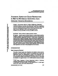
FIG. 1. Ten-rings in atom (middle) and bond representation (right) and their origin in the triangle tiling (left).
FIG. 4. Crack propagation mechanism in the intermittent regime. Top: The crack tip has stopped. Middle: It has emitted a dislocation which is followed by a phason wall. Bottom: The quasicrystal has opened along the wall.
3514 2 FIG. 2. Binary tiling in the bond representation and special planes, whose surface energy is explained in the text.
propagated distance [r0 ]
300.0 1.13% 1.131% 1.14 % 1.3 % 1.5 % 1.6 %
200.0
100.0
0.0 0.0
35.0
70.0 time [t 0 ]
105.0
140.0
FIG. 3. Propagated distance of crack tip versus time. Depending on the dilation three different regimes are found: An intermittent (ε=1.13%, 1.131% and 1.14%), smooth (ε=1.3%) and unstable regime (ε=1.5 and 1.6%).
FIG. 5. Virtual dislocation emission observed at a strain of 1.5% in the bond representation. Top: Snapshot of a simulation after 73.5t0 ; a dislocation has been emitted at an angle of 72◦ . Bottom: After 77t0 the dislocation has returned.
4