fracture, elastic-plastic material, crack-tip field, the J-integral, plane stress, plane strain, ... Characterization of the crack-tip stress and strain fields in a significant ...
International Journal of Fracture 85: 131–155, 1997. c 1997 Kluwer Academic Publishers. Printed in the Netherlands.
Crack-tip fields in elastic-plastic material under plane stress mode I loading F.G. YUAN and S. YANG Department of Mechanical and Aerospace Engineering, North Carolina State University, Raleigh, NC 27695 Received: 8 October 1996; accepted in revised form 20 March 1997
Abstract. Results on the crack-tip fields in an elastic power-law hardening material under plane stress mode I loading are presented. Using a generalized asymptotic expansion of the stress function, higher-order terms are found which have newly-discovered characteristics. A series solution is obtained for the elastic-plastic crack-tip (i) (k) fields. The expansion of stress fields contains both the rti �pq (�; ti ) and Re[rtk �rs (�; tk )] terms where ti is real (i) (k) and tk is complex; the terms �pq (�; ti ) and �rs (�; tk ) are real and complex functions of � respectively. Comparing the results with that for the plane strain mode I loading shows that: (1) the effect of higher-order solutions on the crack-tip fields is much smaller; and (2) the path-independent integral J also controls the secondorder or third-order term in the asymptotic solutions of the crack-tip fields for most of the engineering materials (1 < n < 11) in plane stress, while the J -integral does not control the second and the third-order terms for the plane strain mode I case for n > 3. These theoretical results imply that the crack-tip fields can be well characterized by the J -integral, and can be used as a criterion for fracture initiation under plane stress mode I loading. This is in agreement with existing full-field solutions and experimental data that J at crack growth initiation is essentially independent of in-plane specimen geometry. The comparison confirms the theoretical asymptotic solutions developed in this study. Key words: asymptotic expansion, higher-order terms, Runge–Kutta method, finite elements, crack mechanics, fracture, elastic-plastic material, crack-tip field, the J -integral, plane stress, plane strain, mode I.
1. Introduction Characterization of the crack-tip stress and strain fields in a significant microstructural region is important for justification of fracture criterion. In an elastic power-law hardening material, The HRR solution (Hutchinson, 1968; Rice and Rosengren, 1968) is the leading order term in the asymptotic expansion of the crack-tip fields and is uniquely characterized by a parameter J -integral. Using the J -integral as a single characterizing parameter requires J -dominance, that is, the HRR field must dominate over the region where microscopic fracture process occurs. When J -dominance is lost, the single parameter characterization may be inadequate. In this case, it is necessary to introduce an additional parameter. For the plane strain mode I loading, the loss of J -dominance has been observed in many cases. Numerical results demonstrated that the crack-tip fields may deviate away from the HRR field in the region of interest. Experiments further confirmed J at the crack growth initiation depends heavily on in-plane specimen geometry (or constraint effect). Therefore a single critical value of the J -integral is not sufficient to predict the crack growth initiation. Because of the limitation of the J -dominance, some approaches of two-parameter characterization of the crack-tip fields have been proposed. Li and Wang (1986), Sharma and Aravas (1991) determined the second-order term in the expansion. A more complete analysis for the higherorder terms is given by Yang et al. (1993). Li and Wang (1986) used the amplitude of the second-order term of the stress field as the second parameter. Since the stresses in the
(Kb. 6) INTERPRINT: Shirley. PIPS Nr.: 137584 ENGI frac4166.tex; 5/12/1997; 9:09; v.7; p.1
132
F.G. Yuan and S. Yang
region of interest often cannot be accurately described by a two-term expansion, a multi-term asymptotic solution has been reported by Yang et al. (1991) and Xia et al. (1993). Yang et al. (1991) proposed a three-term asymptotic solution which is characterized by two parameters. Betegon and Hancock (1991), Al-Ani and Hancock (1991), and Du and Hancock (1991) employed the T -stress, which is the second-order term in a linearly elastic crack-tip field, as a valuable additional parameter; O’Dowd and Shih (1991, 1992) suggested the J -Q approach. In marked contrast to the results for plane strain mode I, the crack-tip fields in the case of plane stress mode I can be well characterized by the J -integral. Finite element results reported by Liu and Zhang (1985), Deng and Wang (1989), and Sun (1992) demonstrated that, regardless of the loading level (i.e. from small scale yielding to large scale yielding), the in-plane geometry effect on the crack tip fields is negligible. Experiments performed by Deng and Wang (1989), Kang, Dadkhah and Kobayashi (1989), Kang and Liu (1992), and May and Kobayashi (1995) clearly indicated that J at initiation and the J -resistance curve for small amount of crack growth are also insensitive to in-plane geometry size and configuration for a fixed thickness. The measured displacements uy are well represented by the J -integral. This provides the evidence of a fracture criterion using a single parameter under plane stress mode I condition. Accurate theoretical solutions should be able to support the results by numerical solutions and experimental data and to provide the theoretical basis for a single parameter characterization of the crack-tip fields for the plane stress mode I. Higher-order analysis has been conducted by Yang et al. (1991). The analysis indicates the higher-order solutions can be obtained for n < 3:23. The three-term expansion characterized by two parameters can excellently predict the crack-tip fields. However, when n > 3:23, the higher-order terms with independent parameter cannot be found. Therefore it was implied (Chao, 1993) that a single parameter J can be used as a fracture criterion under plane stress mode I with n > 3:23. Mathematically, since a single parameter in the asymptotic analysis fails to encompass the full-field stress solutions from the crack tip, similar to the eigenfunction analysis in the linearly elastic solids, hence further theoretical studies are needed to elucidate the paradox. In this paper, allowing the stress exponent of the higher-order terms to be complex valued, and seeking the higher-order terms with separable form within the complex domain, the paradox mentioned above can be clarified. Using a generalized asymptotic expansion of the stress function, the higher-order terms with new characteristics are found, and a series solution is obtained for the elastic-plastic crack-tip fields. Comparing the results with that for the plane strain mode I loading shows that: (1) the effect of higher-order terms on the crack-tip fields is less important in plane stress than in plane strain for most engineering materials with power-law hardening; (2) the elastic effect enters the second or third order term for 1 < n < 11, and these terms are controlled by the path-independent integral J , while J does not control the second and the third order terms for the plane strain mode I case for n > 3. These theoretical results imply that the crack-tip fields can be well characterized by J alone for plane stress. Hence the single parameter J can be used as a criterion for fracture initiation in the plane stress state. This is in agreement with existing experiments that J at crack growth initiation is essentially independent of specimen geometry. A comparison of the asymptotic solutions with finite element solutions have been made. This indicates that the asymptotic solutions which contain the higher-order terms can accu-
frac4166.tex; 5/12/1997; 9:09; v.7; p.2
Crack-tip fields in elastic-plastic material under plane stress mode I loading
133
rately describe the stress and deformation crack-tip fields within substantial distance from the crack-tip ranging from small to large scale yielding. 2. Basic equations Crack-tip fields of a crack in an elastic-plastic material under plane stress mode I loading are investigated. The constitutive equation for the material can be described by J2 deformation theory with isotropic power-law hardening, namely 1+�
2�
� � �n 1 s e ij
"ij = E sij + 3E �kk �ij + �"0 � (2.1) �0 ; 0 where "0 ; �0 are yield strain and yield stress in uniaxial tension respectively; �0 = E"0 ; E is Young’s modulus; �; n are material constants and n is referred to strain hardening exponent; "ij ; �ij are strain and stress tensor, and sij = �ij 13 �kk �ij ; �e = ( 32 sij sij )1=2 1
3 2
are the deviatoric stress tensor and effective stress respectively. In the analysis, it is convenient to introduce the normalized variables according to
�ij� = �ij =�0 ; "�ij = "ij ="0 ; u�i = ui ="0 L; x�i = xi=L; where L is a characteristic crack dimension and xi is the Cartesian coordinates. In terms of
these normalized variables, the constitutive equation can be written by dropping the asterisk as
"ij = (1 + ")sij + 1
2" 3
�kk �ij + 32 ��en 1 sij :
(2.2)
Referring to a polar coordinate system, the basic equations under small strain deformation are Strain–displacement relations 1 @u� ur r "rr = @u ; " �� = @r� r @� + �r @u� u� r "r� = 12 1r @u @� + @r r : Compatibility equation
!
(2.3)
!
@2 1 @ " + 2 @ + @2 " r2 @�2 r @r rr r @r @r2 �� 1
2
!
@ + 1 @ 2 " = 0: r2 @� r @r@� r� 1
(2.4)
Equilibrium equations
@�rr + 1 @�r� + �rr ��� = 0 @r r @� r @�r� + 1 @��� + 2�r� = 0: @r r @� r
(2.5)
frac4166.tex; 5/12/1997; 9:09; v.7; p.3
134
F.G. Yuan and S. Yang
Introducing a stress function �, and expressing stresses as
!
� 1 @� � 2� 1 @2� @ � @ @ �rr = r @r + r @�2 ; ��� = @r2 ; �r� = @r r @� 1
(2.6)
the equilibrium equations are automatically satisfied. 3. Asymptotic analysis of crack-tip fields Referring to the polar cylindrical coordinate system with origin located at the crack tip and � = 0 coinciding with crack front, as r ! 0, we seek an asymptotic expansion of the stress function in a separable form
�
� = rt 2f0(�; t0) + 0+
X
Re[r tk +2 fk (� ; tk )];
k =1
k = 1; 2; 3; : : : ;
(3.1)
where
t0 < Re(t1) < Re(t2 ) < � � � To ensure the existence of the solution in the separable form of Equation (3.1), t0 must be real and tk (k > 1) may be complex. Thus f0 is real, fk may be complex. It can be proved that if Im(t0 ) 6= 0, the first term with form r t0 +2 f0 (� ; t0 ) does not exist. If t0 be real and t1 ; t2 ; : : :, be complex, then we can determine solutions for t1 ; t2 ; : : : and f1 ; f2 ; : : : which are governed by linear equations given in the following asymptotic analysis. It follows from Equations (2.6) and (3.1) that the expansion of stress vectors � and s can be expressed as
X � = Re[rtk � (k) (�; tk )] k =0 X tk (k )
s=
k =0
Re[r s
(�; tk )]
as r as r
!0 (3.2)
! 0;
where
= fk00 + (tk + 2)fk ( ) = (tk + 1)(tk + 2)fk ( ) = (tk + 1)fk0 ( ) (k ) = �ij(k) 13 �pp �ij
�rrk ���k �r�k sijk
( )
(3.3)
and the prime denotes derivative with respect to � . Using Equation (3.2) and a binomial theorem to expand the effective stress �e = ( 32 sij sij )1=2 and keeping the terms up to at least the third order, we have
�e = t �e0 + �e0 fRe(rt � 01 ) + Re(rt � 02 ) + 14 Re[r2t + 14 r2 Re t t (� 11 R � 01 �� 01 )g + � � � ; 0
( )
( )
( 1)
0
1
(
)
(
)
(
2
)
(
)
(
)
1
t0
(�(11) (�(01) )2 ] (3.4)
frac4166.tex; 5/12/1997; 9:09; v.7; p.4
Crack-tip fields in elastic-plastic material under plane stress mode I loading
135
where
sij ; (k = 1; 2; : : :) 2(�e )2 1 1 1 1 3sij sij 3sij s�ij 11 11 R = (� ) = ; � : 0 0 2(�e )2 2(�e )2 (�e ) = s s ; � (0)
3 (0) (0) 2 ij ij
2
(0k )
=
3sij
(0) (k ) (0)
( ) ( )
(3.5)
( ) ( )
(
)
( )
( )
The bar over the functions denotes their complex conjugates. Substituting Equations (3.2) and (3.4) into the constitutive Equation (2.2) and using a binomial expansion, the strain vector " can be expanded as
" = �rnt0 "(0) + � Re(r(n
" ) + � Re(r(n
1)t0 +t1 (1)
+� Re(r(n 2)t +2t "(C ) ) + �r(n +rt "e(0) + Re(rt "e(1) ) + � � � ; 0
1
0
" ) + ���
1)t0 +t2 (2)
"
2)t0 +2 Re(t1 ) (R)
as
r!0 (3.6)
1
where
"(0) = 32 (�e(0) )n 1 s(0) "(k) = 32 (�e(0) )n 1 [s(k) + (n 1)�(0k) s(0) ]; k = 1; 2 " # (11) + ( n 3)(� (01) )2 (0) � (01) (1) 3 (0) n 1 (C ) " = 4 (�e ) (n 1) � s + s 2 " # (11)R (01) � + ( n � 3)� (01) � (0) n 1 (0) 3 (01) (1) (R) " = 4 (�e ) (n 1) Re(� �s ) + s 2 "e(k) = (1 + ")s(k) + 1
2" 3
(3.7)
�ppk I: ( )
Note that in the expansion of ", the terms with factor � are plastic components of "; while the other terms are elastic components. Putting Equation (3.6) in Equation (2.4) and making some algebraic manipulation and simplification, the compatibility Equation (2.4) can be expanded as
�rt D(" 0 ; t0 ) + � Re[rt D(" 1 ; t1 )] + � Re[rt D(" 2 ; t2)] + � � � (3.8) +� Re[r2t t D(" C ; 2t1 t0 )] + �r2 Re t t D(" R ; 2 Re(t1) t0) + � � � +r 2 n t D("e 0 ; (2 n)t0) + Re[r 1 n t t D("e 1 ; (1 n)t0 + t1)] + � � � = 0; 0
( ) 1
(
) 0
1
(
0
( )
( )
( )
2
)
( 1)
(
0
) 0+ 1
( )
( )
where D ("; q ) is a linear differential operator defined as
D("; q) = "00rr [(n 1)t0 + q]f"rr [(n 2[(n 1)t0 + q + 1]"0r� :
1)t0 + q + 1]"�� g (3.9)
In order to meet the compatibility equation with different powers of r , we seek to satisfy the equation term-by-term in an asymptotic sense as r ! 0 by collecting the terms with the same
frac4166.tex; 5/12/1997; 9:09; v.7; p.5
136
F.G. Yuan and S. Yang
power of r in Equation (3.8). It can be readily shown that the first term in the compatibility equation is the dominant term as r ! 0. Therefore, to the leading order, the compatibility equation becomes
D(" 0 ; t0 ) = 0: ( )
Once the leading term solution is determined, the elastic term D ("e(0) ; t0 ) relying on the leading term is completely decided and is a non-zero term, that is
D("e 0 ; (2 n)t0) 6= 0 ( )
0 1 in Equation (3.8) leads to the following two cases: (1)
rtk D(" k ; tk ) is balanced by itself. This leads to linear homogeneous governing equa-
(2)
rtk D(" k ; tk ) is balanced by the non-zero terms which can have the order rtk . This yields
( )
tions;
( )
linear nonhomogeneous governing equations. In this case, we will face several choices, in general.
frac4166.tex; 5/12/1997; 9:09; v.7; p.7
138
F.G. Yuan and S. Yang
Hence, to solve this problem, first, we must list all possible options for balancing the terms rtk D("(k) ; tk ), then choose one from the options by trial with each value n. Based on the previous analysis, we have the following governing equations Leading order term With the coefficient of the dominant term in Equation (3.8) set to zero, the leading order term is governed by
D(" 0 ; t0 ) = 0; ( )
(4.1)
with homogeneous boundary conditions
f00 (0) = f0000(0) = f0(�) = f00 (�) = 0: This is a nonlinear eigenvalue problem. The nonlinear fourth-order differential Equation (4.1) about f0 has been solved and the numerical solution is called the HRR solution (Hutchinson, 1968; Rice and Rosengren, 1968) with t0 = 1=(n + 1). Once the leading order solution is found, we can determine the next order term. For the higher-order terms, in order to derive general governing equations for any value of n, many cases need to be considered. For convenience, first we define the following linear eigenvalue problems
D(" k ; tk ) = 0; k > 1 fk0 (0) = fk000(0) = fk (�) = fk0 (�) = 0: ( )
(4.2)
The expression of "(k) from equation (3.7) indicates that "(k) depends on t0 ; tk ; f0 ; fk and their derivatives only. i.e., "(k) = "(k) (fk ; fk0 ; fk00 ; f0 ; f00 ; f000 ; tk ; t0 ). Therefore "(k) is a linear function of fk and its derivatives. In addition, D ("(k) ; tk ) is a linear operator of "(k) . Thus, Equation (4.2) is a linear fourth-order ordinary differential equation of fk . Equations (4.2) yield eigenvalues
t�1 ; t�2 ; t�3 ; : : : ; where
t0 < Re(t�1 ) < Re(t�2 ) < � � � : (4.3) Note that we can easily get t�1 ; t�2 ; : : : and corresponding f1� ; f2� ; : : : : However, the values of t1; t2; : : : in Equation (3.1) are yet to be determined. Since, at present, the governing equations for (tk ; fk ) have not developed yet, the (t�k ; fk� ) given by Equation (4.2) may not be the actual tk and fk in the asymptotic expansion solution. Second-order term From the expansion of the compatibility equation, it can be seen that there are three choices for the second order balancing. (1)
rt D(" 1 ; t1 ) = 0 1
( )
if
t1 = t�1 ;
frac4166.tex; 5/12/1997; 9:09; v.7; p.8
Crack-tip fields in elastic-plastic material under plane stress mode I loading
139
�rt D(" 1 ; t1 ) + r 2 n t D("e 0 ; (2 n)t0) = 0 if t1 = (2 n)t0; r 2 n t D("e 0 ; (2 n)t0) = 0 if t1 > (2 n)t0; Clearly, the last choice is excluded because D ("e 0 ; (2 n)t0 ) 6= 0. Thus for a given n, the (2) (3)
( )
1
(
) 0
(
( )
) 0
( )
( )
governing equation is determined from one of the first two cases by choosing the smaller value for Re(t1 ). Hence it can be concluded that for any given value of n, the stress exponent t1 can be expressed as
t1 2 ft�1 ; (2 n)t0 g Re(t1 ) = Min Reft�1 ; (2 n)t0 g Re t >t ( 1)
(4.4)
0
and the governing equations can be obtained from the corresponding cases (1) or (2). It is apparent from the above discussion that the form of the governing equation depends solely on the values of n. Applying this approach to the value of n in the range of n > 1, we have the following governing equations: (i) When 1 < n < 4:45; t1
= (2 n)t0 , �D("(1) ; t1) + D("e(0) ; (2 n)t0) = 0; (4.5) f10 (0) = f1000(0) = f1(�) = f10 (�) = 0 (ii) When n > 4:45; t1 = t�1 , D("(1) ; t1 ) = 0; (4.6) f10 (0) = f1000(0) = f1(�) = f10 (�) = 0: Note that when t1 = t�1 , we may have complex-valued t1 and f1 . In this case, the complex conjugate of the governing Equation (4.6) is
D(�" 1 ; t�1 ) = 0; f�10 (0) = f�1000(0) = f�1(�) = f�10 (�) = 0 ( )
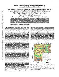
and it implies that if t1 and f1 satisfy the Equation (4.5), so do t�1 and f�1 . In other words, the complex solution for Equation (4.5) occurs in conjugate pairs t1 and f1 ; t�1 and f�1 . The values of t1 are listed in Table 1a for integer values of n in the region 1 < n 6 20. The variation of Re(t1 ) with n is shown in Fig. 1a. For comparison, the corresponding values for the plane strain case are calculated and shown in Table 1b and Figure 1b. Note that for plane strain mode I case the complex-valued stress exponents can also be found, but they cannot enter the first four terms. Third-order term Removing the balancing second-order terms from Equation (3.8), we have the following possibilities or cases for the third-order term balancing.
= t�1 1. r t D ("(2) ; t2 ) = 0
when t1 2
if t2
= t�2
frac4166.tex; 5/12/1997; 9:09; v.7; p.9
140
F.G. Yuan and S. Yang
Table 1a. Higher-order stress exponents under plane stress mode I loading n
t1
9 0 = 0:25 (n ; 0:4
2 3 4 5 6 7 8 9 10 11 12 13 14 15 16 17 18 19 20
t2
t3
0:1371 0:3496 0:4621 + 0:2194 i 0:5 0:5714 0:625 (n 2)=(n + 1) 0:6667 0:7 0:7273 0:7491 + 0:3068 i 0:7233 + 0:2976 i 0:7002 + 0:2883 i 0:6797 + 0:2791 i 0:6609 + 0:2700 i 2t1 t0 0:6438 + 0:2612 i 0:6280 + 0:2526 i 0:6132 + 0:2445 i 0:5996 + 0:2367 i 0:5866 + 0:2292 i
0:3333 = (2n 3)=(n + 1) 0:6097 1 = (2n 3)=(n + 1) 1:0360 + 0:2910 i 0:9621 + 0:3187 i 0:9022 + 0:3277 i 2t1 t0 0:8533 + 0:3275 i 0:8128 + 0:3227 i 0:7785 + 0:3154 i 0:75 0:7692 0:7857 0:8 0:8125 (n 2)=(n + 1) 0:8235 0:8333 0:8421 0:85 0:8571
2)=(n + 1)
9 > > > > > > =
0:4347 + 0:2910 i 0:4096 + 0:3187 i 0:3886 + 0:3277 i 0:3711 + 0:3275 i 0:3564 + 0:3227 i 0:3438 + 0:3154 i 0:3329 + 0:3068 i 0:3232 + 0:2976 i 0:3144 + 0:2883 i 0:3065 + 0:2791 i 0:2992 + 0:2700 i 0:2925 + 0:2612 i 0:2862 + 0:2526 i 0:2803 + 0:2445 i 0:2748 + 0:2367 i 0:2695 + 0:2292 i
> > > > > ;
9 > > > > > > > > > > > > > = > > > > > > > > > > > > > ;
9 > > > > > > =
9 > > > > > > > > > > > > > = > > > > > > > > > > > > > ;
> > > > > ;
Note: There are two stress exponents for t2 and t3 in the following ranges t2 = 2t1 t3 = 2t1
t0 ; 2 Re(t2 ) t0 ; 2 Re(t2 )
6
t0 ; for 11 n; t0 ; for 4:45 < n < 11:
The table only shows the complex-valued exponents.
Figure 1. Variation of stress exponents tk with n for plane stress and plane strain mode I.
�rt D(" 2 ; t2 ) + r 2 n t D(" e 0 ; (2 n)t0 ) = 0 if t2 = (2 n)t0 3. r t D (" 2 ; t2 ) + r 2t t D (" C ; 2t1 t0 ) = 0 if t2 = 2t1 t0 4. r t D (" 2 ; t2 ) + r 2 Re t t D (" R ; 2 Re(t1 ) t0 ) = 0 if t2 = 2 Re(t1 ) t0 2.
2
( )
2
( )
2
( )
( 1
) 0
( ( )
(
0
( 1)
0
)
( )
frac4166.tex; 5/12/1997; 9:09; v.7; p.10
Crack-tip fields in elastic-plastic material under plane stress mode I loading
141
Table 1b. Higher-order stress exponents under plane strain mode I loading n
2 3 4 5 6 7 8 9 10 11 12 13 14 15 16 17 18 19 20
t1
0:1019 0:01284 0.03282 0.05456 0.06484 0.06937 0.07089 0.07078 0.06977 0.06827 0.06653 0.06468 0.06279 0.06093 0.05911 0.05735 0.05565 0.05403 0.05250
t2
t3
0 0.2243 0.2656 0.2758 0.2725 0.2637 0.2529 0.2416 0.2305 0.2199 0.2100 0.2008 0.1923 0.1844 0.1770 0.1703 0.1639 0.1581 0.1526
0.1295 0.25 0.3598 0.3407 0.3238 0.3085 0.2944 0.2815 0.2695 0.2586 0.2484 0.2390 0.2302 0.2220 0.2144 0.2073 0.2006 0.1944 0.1885
when t1
= (2 n)t0, we have the following possibilities: 5. r D ("(2) ; t2 ) = 0 if t2 = t�1 �rt D("(2) ; t2 ) + r2t t [�D("(C ) ; 2t1 t0) 6. if t2 = (1 n)t0 + t1 +�D("(R) ; 2t1 t0) + D("e(1) ; (1 n)t0 + t1)] = 0: Clearly, in the case of (6), t2 = (1 n)t0 + t1 = 2t1 t0 = 2 Re(t1 ) t0 = (3 2n)t0 and D("(C ) ; 2t1 t0 ) = D("(R) ; 2t1 t0 ). Thus, the governing equation can be rewritten as t2
2
1
0
�D(" 2 ; t2 ) + 2�D(" C ; 2t1 t0) + D("e 1 ; (1 n)t0 + t1) = 0: For a given n, one of the six cases gives the governing equation for the third term and this case also provides the minimum value for Re(t2 ). Therefore, we can conclude, for any given value of n; t2 is determined by t2 2 ft�1 ; t2� ; 2t1 t0; 2 Re(t1) t0; (2 n)t0; (1 n)t0 + t1 g Re(t2 ) = Min Reft�1 ; t�2 ; 2t1 t0 ; (2 n)t0 ; (1 n)t0 + t1 g: (4.7) Re t >Re t ( )
(
( 2)
)
( )
( 1)
The governing equations can be obtained from the corresponding cases (1) to (6) which can be solved with homogeneous boundary conditions. Note that the cases (3) and (4) lead to the governing equations
D(" 2 ; t2 ) + D(" C ; 2t1 t0) = 0; t2 = 2t1 t0 ( )
(
)
(4.8)
frac4166.tex; 5/12/1997; 9:09; v.7; p.11
142
F.G. Yuan and S. Yang
D(" 2 ; t2 ) + D(" R ; 2 Re(t1 ) t0) = 0; t2 = 2 Re(t1 ) t0: (4.9) Both cases provide the same value of Re(t2 ). Because r 2t t and r 2 Re t t have the same order as r ! 0, it means that if Re(t2 ) = 2 Re(t1 ) t0 , then the third-order term in the expansion of � has the form rt 2f2(�; t2) + rRe t 2 f^2(�; Re(t2 )); t2 = 2t1 t0; where f2(�; t2 ) and f^2(�; Re(t2 )) are determined by Equations (4.8) and (4.9) respectively. ( )
( )
1
2+
0
( 1)
0
( 2 )+
Conversely, if, at the beginning, we assume that the third-order term in Equation (3.1) has the form
rt 2f2(�; t2) + rRe t 2+
( 2 )+2
f^2(�; Re(t2 ))
then the same results for the third-order term can be obtained. Further, when Im(t1 ) = 0, we have t2 = 2t1 t0 = 2 Re(t1 ) t0 and the governing Equations (4.8) and (4.9) can be reduced to a single equation. i.e.,
D(" 2 ; t2 ) + 2D(" R ; 2t1 t0) = 0; t2 = 2t1 t0: Lastly, for the third term, we may have complex-valued t2 and f2 resulting from the cases (1) ( )
( )
and (3)
D(" 2 ; t2 ) = 0 D(" 2 ; t2 ) + D(" C ; t2 ) = 0; t2 = 2t1 t0: ( ) ( )
(
)
(4.10) (4.11)
The complex conjugates of Equations (4.10) and (4.11) are
D(�" 2 ; t�2 ) = 0 D(�" 2 ; t�2 ) + D(�" C ; t�2 ) = 0; t�2 = 2t�1 t0: ( ) ( )
(
)
(4.12) (4.13)
This indicates that the complex solutions for equation (4.10) appear in conjugate pairs, t2 and f2, t�2 and f�2, and that the complex solutions for Equation (4.11) occur in conjugates pairs (f2; f1; and t1); (f�2 ; f�1 ; and t�1). Choosing t2 from Equation (4.7) and taking the governing equations from the corresponding cases for n > 1, we have the following final results (i) 1 < n < 1:58; t1 = (2 n)t0 ; t2 = (3 2n)t0 = (1 n)t0 + t1 = 2t1 t0 �D(" 2 ; t2 ) + 2�D(" C ; t2 ) + D("e 1 ; t2 ) = 0 (ii) 1:58 < n < 4:45; t1 = (2 n)t0 ; t2 = t�1 D(" 2 ; t2 ) = 0; ( )
(
)
( )
( )
where
t2 = t�1 (real) t2 = t�1 (complex)
1:58 < n < 3:23 3:23 < n < 4:45
frac4166.tex; 5/12/1997; 9:09; v.7; p.12
Crack-tip fields in elastic-plastic material under plane stress mode I loading
143
That is, when n increases near 3.23, the values of t2 change from real to complex (see the following Section 6). (iii) 4:45 < n < 11;
t1 = t�1 (complex); t2 = (2 n)t0
�D(" 2 ; t2 ) + D("e 0 ; (2 n)t0) = 0 (iv) 11 < n; t1 = t�1 (complex); Re(t2 ) = 2 Re(t1 ) t0 ( )
( )
D(" 2 ; t2 ) + D(" C ; 2t1 t0) = 0; t2 = 2t1 t0 D(" 2 ; t2 ) + D(" R ; 2 Re(t1 ) t0) = 0; t2 = 2 Re(t1) t0 ( )
(
)
( )
( )
In the above case, the third-order term can be divided into two parts, one is related to the complex stress exponent; the other is associated with the real stress exponent. Note that from the numerical results, the case (1), t2 = t�2 , is impossible to occur. Fourth-order term The fourth-order term and even higher-order terms can be pursued in a similar manner. However, there are more choices involved for the higher-order balancing. For example, for a given value of n; Re(t3 ) can be given by Re(t3 ) =
Min
Re(t3 )>Re(t2 )
Re
ft�1 ; t�2 ; t�3 ; 2t1 t0; 3t1
2t0 ; t1 + t2
t0;
(2 n)t0; (1 n)t0 + t1; (1 n)t0 + t2 g:
(4.14)
The other detailed results will not be presented here. The method in determining governing equations for higher-order terms is valid for all values of n. (n > 1). Several examples are presented below: when n = 3
t0 =
1 ; 4
t1� = 0:3496; t�2 = 0:6097; t�3 = 1:5102
when n = 5
t0 =
1 ; 6
t1� = 0:4347 + 0:2910 i; t�2 = 1:4521 + 0:3960 i
when n = 8
t0 =
1 ; 9
t1� = 0:3711 + 0:3275 i; t�2 = 1:2912 + 0:5262 i
when n = 10
t0 =
1 ; 11
t�1 = 0:3438 + 0:3153 i; t�2 = 1:1886 + 0:5454 i
frac4166.tex; 5/12/1997; 9:09; v.7; p.13
144
F.G. Yuan and S. Yang
Therefore we have the following results
n)t0; t2 = t�1 ; t3 = t�2 t2 = (2 n)t0; Re(t3 ) = 2 Re(t1 ) t0 t2 = (2 n)t0; Re(t3 ) = 2 Re(t1 ) t0 t2 = (2 n)t0 ; Re(t3) = 2 Re(t1 ) t0: Repeating the procedure for other values of n, we can get Table 1a and Figure 1a which show the variation of tk with value of n. The governing equations with homogeneous boundary n = 3 : t1 = (2 n = 5 : t1 = t�1 ; n = 8 : t1 = t�1 ; n = 10 : t1 = t�1 ;
conditions can be solved numerically. Hence, the angular distribution of the crack-tip fields are obtained. Sometimes it is convenient to express the expansion of � in the form
� = A0rt +2 f0(�; t0 ) + 0
X
k =1
Re[Ak r tk +2 fk (� ; tk )];
k = 1; 2; 3; : : : ;
(4.15)
where Ak are amplitudes, A0 is real; A1 ; A2 ; : : : may be complex. It follows from Equation (4.15) that the stress, strain, and displacement expansions are
�=
X
k =0
Re[Ak r tk � (k) (� ; tk )]
as r
! 0;
" = �An0 rnt0 "(0) + � Re(An0 1 A1r(n
(4.16)
" )
1)t0 +t1 (1)
+� Re(An0 1A2 r(n 1)t +t "(2) ) + � � � +� Re(An0 2A21 r(n 2)t +2t "(C ) ) + �An0 2 jA1j2 r(n +A0rt "e(0) + Re(A1 rt "e(1) ) + � � � ; 0
2
0
0
1
1
"
2)t0 +2 Re(t1 ) (R)
(4.17)
= �A0n rnt +1u(0) + � Re(An0 1 A1 r(n 1)t +t +1u(1) ) +� Re(An0 1 A2r(n 1)t +t +1u(2) ) + � � � +� An0 2r(n 2)t +2 Re(t )+1 Re(A21 r2i Im(t ) u(C ) ) + jA1 j2u(R) ) + � � � (4.18) +A0 rt +1ue(0) + Re(A1 rt +1 ue(1) ) + � � � ; where Ak is an arbitrarily independent parameter, if the governing equation for fk is homogeneous; Ak is not an independent parameter, if the equation is nonhomogeneous. Without loss of generality, in the case of nonhomogeneous equation, Ak can be chosen as Ak = � 1A20 n if tk = (2 n)t0 A2 = A21 =A0 if t2 = 2t1 t0 A2 = jA1 j2 =A0 if t2 = 2 Re(t1) t0 A2 = � 2 A30 2n if t2 = (1 n)t0 + t1 u
0
0
0
0
0
1
2
1
1
1
frac4166.tex; 5/12/1997; 9:09; v.7; p.14
Crack-tip fields in elastic-plastic material under plane stress mode I loading
145
Selecting such Ak leads to simplified forms of the governing equations. That is, the form of the new governing equations is independent of � in the corresponding equations given previously. When fk is governed by a homogeneous equation, if fk is a solution, so is any multiple of fk. (0) Therefore some proper normalization must be imposed. For the leading term, (�e )max = 1 is used; for the higher-order terms, fk00 (0) = 1 is adopted in this paper. The governing equations can be solved by a shooting method. In the integration procedure, a Runge–Kutta method with adaptive step size and multi-dimensional Newton–Raphson method is used. The unknown amplitude Ak cannot be determined from an asymptotic analysis. In general, it depends on the geometry of the cracked body, far field loading, and material parameters. However, from the path independent J -integral, it can be found (Hutchinson, 1968; Rice and Rosengren, 1968) that
�1= n 1 J A0 = �" � In L ; 0 0 �
( + )
where In is an integration constant which is a function of n only. Collecting the terms with like powers of r in Equations (4.16)–(4.18) and taking the first three terms for 1 < n < 20, we have the following three-term expansion of the crack-tip fields 1 < n < 1:58
� = A0rt0 � (0) + � 1 A20 n r(2 n)t0 � (1) + � 2A30 2n r(3 2n)t0 � (2) " = �An0 rnt0 "(0) + A0 rt0 ("(1) + "e(0) ) + � 1 A20 n r(2 n)t0 ("(2) +2"(R) + "e(1) )
(4.19)
u = �An0 r nt0 +1 u(0) + A0 r t0 +1 (u(1) + ue(0) )
+� 1 A20 n r(2
n)t0 +1
(u(2) + 2u(R) + ue(1) )
1:58 < n < 3:23
� = A0rt0 � (0) + � 1 A20 n r(2 n)t0 � (1) + A2rt2 � (2) " = �An0 rnt0 "(0) + A0 rt0 ("(1) + "e(0) ) + �An0 1 A2r(n u = �An0 r nt0 +1 u(0) + A0 r t0 +1 (u(1) + ue(0) ) + �An0
1
"
1)t0 +t2 (2)
A2r n (
(4.20)
1)t0 +t2 +1 (2)
u
where A2 is an independent real parameter. 3:23 < n < 4:45
� = A0rt0 � (0) + � 1 A20 n r(2 n)t0 � (1) + Re(A2 rt2 � (2) ) " = �An0 rnt0 "(0) + A0 rt0 ("(1) + "e(0) ) + �An0 1 Re[A2 r(n u = �An0 r nt0 +1 u(0) + A0 r t0 +1 (u(1) + ue(0) ) + �An0
1
" ]
1)t0 +t2 (2)
Re[A2 r (n
(4.21)
1)t0 +t2 +1 (2)
u
]
where A2 is an independent complex parameter;
frac4166.tex; 5/12/1997; 9:09; v.7; p.15
146
F.G. Yuan and S. Yang
4:45 < n < 11
� = A0rt0 � (0) + Re(A1 rt1 � (1) ) + � 1 A20 n r(2 n)t0 � (2) " = �An0 rnt0 "(0) + �An0 1 Re[A1 r(n 1)t0 +t1 "(1) ] + A0 rt0 ("(2) + "e(0) ) u = �An0 r nt0 +1 u(0) + �An0
1
Re[A1 r (n
1)t0 +t1 +1 (1)
u
(4.22)
] + A0rt +1 (u(2) + ue(0) ) 0
where A1 is an arbitrary complex parameter; n > 11 � = A0 rt � 0 + Re(A1 rt � 1 ) + A0 1 r2 Re t t [Re(A21 r2i Im t � 2 ) + jA1 j2�^ 2 ] " = �A0n rnt " 0 + �An0 1 Re[A1 r n 1 t t " 1 ] +�An0 2 Re[A21 r n 2 t 2t (" 2 + " C )] (4.23) +�An0 2 jA1 j2r n 2 t 2 Re t (^" 2 + " R ) 0
( )
0
( 1)
( )
(
) 0+
(
u
( )
1
) 0+
1
(
) 0+ 1
( )
(
( 1)
0
( 1)
( )
( )
( )
)
( )
( )
= �A0n rnt +1u(0) + �An0 1 Re[A1r(n 1)t +t +1u(1) ] +�An0 2 Re[A21 r(n 2)t +2t +1(u(2) + u(C ) )] 0
0
0
+�An0 2 jA1 j2r(n
1
1
2)t0 +2 Re(t1 )+1
(^u(2) + u(R) )
(4.24)
where A1 is an independent complex parameter;
� (2) ; "(2) , and u(2) are obtained from f2(�; 2t1 t0) which satisfies Equation (4.8); �^ (2) ; "^(2) , and u^(2) are obtained from f^2(�; 2 Re(t1 ) t0) which satisfies Equation (4.9). Clearly the elastic effects enter the second order for 1 < n < 4:45; the third term for 4:45 < n < 11. These higher-order terms are solely controlled by the J -integral. The three-term expansions (4.19)–(4.22) can be presented by the following compact form
� = A0rt0 � (0) + Re(A1 rt1 � (1) ) + Re(A2 rt2 � (2) ) " = �An0 rnt0 "(0) + �An0 1 Re(A1 r(n 1)t0 +t1 "~(1) ) +�An0 1 Re(A2 r(n 1)t0 +t2 "~(2) ) u = �An0 r nt0 +1 u(0) + �An0
+�An0
1
Re(A2 r (n
1
Re(A1 r (n
~ )
(4.25)
~ )
1)t0 +t1 +1 u(1)
1)t0 +t2 +1 u(2)
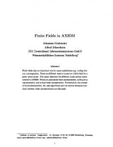
~(k) ; u~(k) ; : : : (k = 1; 2) can be simply obtained from for 1 < n < 11. The expressions for " Equations (4.19) to (4.22) depending on the value of n, and they will not be presented here. Figures 2–4 show the angular distributions of the second-order and third-order stress and strain fields for n = 3; 5, and 10. Because tk appears in conjugate pairs, these figures are (1) (1) (2) (2) presented according to tk = Re(tk ) + ijIm(tk )j. The values of �rr ; ��� ; �rr ; ��� at � = 0 for n = 3; 5; 8, and 10 are also listed in Table 2.
frac4166.tex; 5/12/1997; 9:09; v.7; p.16
Crack-tip fields in elastic-plastic material under plane stress mode I loading
147
(k)
Table 2. Values of higher-order stress angular distributions �ij at � = 0 (1)
(1)
n
�rr
���
3 5 8 10
1.574 1:276 + 0:2380 i 1:217 + 0:2531 i 1:195 + 0:2529 i
0.03175 0:3261 + 0:4217 i 0:2140 + 0:4179 i 0:1825 + 0:4014 i
(2)
�rr
1.281 0.1264 0:1567 0:1292
(2)
���
0.3796 0:08052 0:1499 0:1385
Figure 2. Angular distributions of the higher-order stress and strain fields for n = 3, plane stress mode I.
5. Comparison with finite element solutions In order to verify the asymptotic solutions developed in this paper, the three-term expansions are compared with the finite element solutions. Single-edge crack tension panels (SENT) with a=w = 0:3 have been analyzed, where a is the crack length; w is the width of the specimen. The values of the material properties used in the calculations are �0 = 414 MPa; "0 = 0:002; " = 0:3; � = 1. The analysis is carried out for two different values of the hardening exponents n = 3 and 8 to model high hardening and moderate (or low) hardening materials respectively.
frac4166.tex; 5/12/1997; 9:09; v.7; p.17
148
F.G. Yuan and S. Yang
Figure 3. Angular distributions of the higher-order stress fields for n = 5 and 10, plane stress mode I.
The numerical computation is implemented in the ABAQUS finite element code. Eight-node isoparametric elements with 3 � 3 Gauss integration are used. The smallest crack-tip element size is 5 � 10 6 a. Since the three-term expansion includes one unknown parameter (for n = 3, the parameter is A2 and A2 is real; for n = 8, the parameter is A1 and A1 is complex), the values of the parameters are determined by matching the three-term expansion with finite element solutions. Note that the values can be evaluated from stress components at proper distance r inside the plastic zone as long as r=rp � 1, where rp is the maximum radial extent of the plastic zone. In this study, for simplicity, the matching is enforced �r and/or �� at r=(J=�0 ) � = 2 with
frac4166.tex; 5/12/1997; 9:09; v.7; p.18
Crack-tip fields in elastic-plastic material under plane stress mode I loading
149
Figure 4. Angular distributions of the higher-order strain fields for n = 5 and 10, plane stress mode I.
� = 0 or small angles. Once the values are determined, the entire stress and deformation fields are also determined and are represented in the following Figures 5–9. Results show that the values of the unknown parameters determined from different stress components at various proper locations vary slightly. And this can be seen from the fact that although the parameters are determined by simple point matching, the full agreement between asymptotic stress and deformation fields by the three-term expansion and the full-field solutions by finite element analysis has been achieved. Figures 5–7 show the angular variations of stress and strain fields for n = 8, at radial distances r=(J=�0 ) = 2:11 and 4.57 under applied J = 13:0 KPa�m. Figures 8–9 depict the radial variations of stress and strain and displacement fields along different angles � for n = 3
frac4166.tex; 5/12/1997; 9:09; v.7; p.19
150
F.G. Yuan and S. Yang
Figure 5. Stress angular distributions at r=(J=�0 ) = 2:11 for SENT specimen, n = 8.
at J = 120 KPa�m. In these Figures �ij and "ij are normalized by �0 and "0 respectively; ui and r are non-normalized displacements and radial distance. Obviously, the three-term expansion agrees well with the results obtained from finite element analysis, and improves the leading order solutions in the crack-tip region. Experimental results (Kang et. al., 1989; Kang and Liu, 1992; May and Kobayashi, 1995) also show that the HRR solutions dominate over a larger region for strain "y and displacement uy than for "x and ux . The three-term solutions demonstrate the similar trend as the experimental observations.
6. Discussion and conclusions Asymptotic solutions for the crack-tip fields under plane stress mode I loading indicate that when n increases near n � = 3:23 the stress exponents t2 and t3 merge from two different real values to one pair of complex value (see Figure 1a), and associated amplitudes change from two real arbitrary constants to one complex arbitrary constants. It can be seen from the
frac4166.tex; 5/12/1997; 9:09; v.7; p.20
Crack-tip fields in elastic-plastic material under plane stress mode I loading
151
Figure 6. Stress angular distributions at r=(J=�0 ) = 4:57 for SENT specimen, n = 8.
following numerical results:
n = 3:1; t1 = (2 n)t0; t2 = t1� = 0:3835; t3 = t�2 = 0:5751; t�3 = 1:5083 � 0:1661 i n = 3:2; t1 = (2 n)t0; t2 = t1� = 0:4377; t3 = t�2 = 0:5191; t�3 = 1:5063 � 0:1888 i n = 3:22; t1 = (2 n)t0; t2 = t�1 = 0:4646; t3 = t�2 = 0:4918; t�3 = 1:5059 � 0:1929 i n = 3:3; t1 = (2 n)t0; t2 = t1� = 0:4772 � 0:07489 i; t�2 = 1:5043 � 0:2084 i n = 3:5; t1 = (2 n)t0; t2 = t1� = 0:4738 � 0:1389 i; t�2 = 1:5000 � 0:2418 i
frac4166.tex; 5/12/1997; 9:09; v.7; p.21
152
F.G. Yuan and S. Yang
Figure 7. Strain angular distributions at r=(J=�0 ) = 2:11 and 4.75 for SENT specimen, n = 8.
The first four terms are related to real stress exponents in the range of 1 < n < 3:23; the complex stress exponent t2 enters the third term ranging from 3:23 < n < 4:45; for n > 4:45 the complex exponent enters the second order. The complex stress exponent yields the higher(k ) order term with a form Re[Ak r tk �rs (� ; tk )] in the stress expansion. This explains why the higher-order terms with real stress exponents and independent amplitude cannot be found when n > 3:23. Note that, in the plane strain case, the higher-order terms with complexvalued stress exponents can also be found. However the terms can not enter the first four terms in the series expansion.
frac4166.tex; 5/12/1997; 9:09; v.7; p.22
Crack-tip fields in elastic-plastic material under plane stress mode I loading
153
Figure 8. Radial distributions of ��� and "yy at � = 0� ; 45� and 90� , SENT, n = 3.
Let [tk ]ps and [tk ]pe be the stress exponent for the mode I plane stress and plane strain cases respectively. Comparing the stress exponents between these two cases (see Figure 1 and Table 1) reveals that Re[tk (n)]ps
> [tk (n)]pe k = 1; 2; 3 n > 2 Re[t1 (n)]ps = [t3 (n)]pe 3 6 n 6 3:73 Re[t1 (n)]ps > [t3 (n)]pe n > 3:73
(6.1) (6.2) (6.3)
Knowing that the leading term has the identical singularity for each case, Equation (6.2) and (6.3) clearly indicate that when r ! 0, the effects of higher-order terms on the crack-tip
frac4166.tex; 5/12/1997; 9:09; v.7; p.23
154
F.G. Yuan and S. Yang
Figure 9. Radial distributions of ux and uy at � = 30� ; 60� and 90� , SENT, n = 3.
fields in the plane stress case are so small that even the magnitude of the second-order term is less than that of the fourth-order term in the plane strain case for n > 3:73, and the two terms are of the same order of magnitude for 3 6 n 6 3:73. The range n > 3 covers most engineering materials with power law hardening. In addition, the second- or third-order term is described by the J -integral in plane stress for 1 < n < 11, while the second and third term are controlled by a new parameter instead of the J -integral in plane strain for n > 3 (Yang et al. (1991)). In contrast to the plane stress case, the higher-order terms in the plane strain case plays a more significant role in predicting the crack tip fields than in the case of plane stress. This suggests that the region of J -dominance is much larger in plane stress than in plane strain, and the crack-tip fields can be better described by the J -integral in plane stress
frac4166.tex; 5/12/1997; 9:09; v.7; p.24
Crack-tip fields in elastic-plastic material under plane stress mode I loading
155
than in plane strain. This is in consistent with the well-known fact that (1) for plane stress, the in-plane geometry effect on the crack-tip fields is negligible, the J -integral at crack initiation is essentially independent of the specimen geometry; and (2) for plane strain, there are many cases in which the crack-tip fields may be far from the HRR singular fields, the cleavage fracture toughness of the specimens depend heavily on the specimen geometry. Acknowledgment This research is supported by the Air Force Office of Scientific Research Grant No. F4962095-1-0256. References Al-Ani, A.M. and Hancock, J.W. (1991). J -dominance of short cracks in tension and bending. Journal of the Mechanics and Physics of Solids 39(1), 23–43. Betegon, C. and Hancock, J.W. (1991). Two-parameter characterization of elastic-plastic crack-tip fields. ASME, Journal of Applied Mechanics 58(1), 104–110. Chao, Y.J. (1993). On a single parameter controlled fracture of solids under plane stress conditions. International Journal of Fracture 62(1), R7–10. Deng, H. and Wang, T. (1989). Plane stress elastic-plastic fracture criterion and stress-strain field around crack tip. Advanced in Fracture Research. ICF-7, 323–331. Du, Z.Z. and Hancock, J.W. (1991). The effect of non-singular stress on crack-tip constraint. Journal of the Mechanics and Physics of Solids 39(1), 555–567. Hutchinson, J.W. (1968). Singular behavior at the end of a crack in a hardening material. Journal of the Mechanics and Physics of Solids 16(1), 13–31. Kang, B.S., Dadkhah, M.S. and Kobayashi, A.S. (1989). J -resistance curves of aluminum specimens using Moire interferometry. Proceedings of 1989 Society of Experimental Mechanics, 317–322. Kang, B.S. and Liu, Q. (1992). Crack-tip blunting, initiation, and growth analysis of aluminum single-edge-notched tensile (SENT) specimens by Moire interferometry. Fracture Mechanics: Twenty-Second Symposium (Edited by A. Ernst et al.), ASTM STP 1131(1), 222–247. Li, Y. and Wang, Z. (1986). Higher-order asymptotic field of tensile plane-strain nonlinear crack problems. Scientia Sinica (series A) 29(9), 941–955. Liu, H.W. and Zhang, T. (1985). A dual-parameter elastic-plastic fracture criterion. International Journal of Fracture 27(3–4), R87–291. May, G.B. and Kobayashi, A.S. (1995). Plane stress stable crack growth and J -integral/HRR field. International Journal of Solids and Structures 32(6/7), 857–881. O’Dowd, N.P. and Shih, C.F. (1991). Family of crack-tip fields characterized by a triaxiality parameter-I. Structure of fields. Journal of the Mechanics and Physics of Solids 39(8), 989–1015. O’Dowd, N.P. and Shih, C.F. (1992). Family of crack-tip fields characterized by a triaxiality parameter-II. Fracture Applications. Journal of the Mechanics and Physics of Solids 40(5), 939–963. Rice, J.R. and Rosengren, G.F. (1968). Plane strain deformation near a crack tip in a power-law hardening material. Journal of the Mechanics and Physics of Solids 16(1), 1–12. Sharma, S.M. and Aravas, N. (1991). Determination of higher order terms in asymptotic crack tip solutions. Journal of the Mechanics and Physics of Solids 39(8), 1043–1072. Sun, J. (1992). Mode I plane stress crack-tip constraint for elastic-plastic materials with different strain hardening. International Journal of Fracture 54(3), 235–242. Xia, L., Wang, T.C. and Shih, C.F. (1993). Higher-order analysis of crack tip fields in elastic power-law hardening materials. Journal of the Mechanics and Physics of Solids 41(4), 665–687. Yang, S., Chao, Y.J. and Sutton, M.A. (1991). Higher order asymptotic crack tip fields in a power-law hardening materials. Engineering Fracture Mechanics 45(1), 1–20. Yang, S., Chao, Y.J. and Sutton, M.A. (1993). Complete theoretical analysis for higher order asymptotic terms and the HRR zone at a crack tip for mode I and mode II loading of a hardening material. Acta Mechanica 98(1), 79–98.
frac4166.tex; 5/12/1997; 9:09; v.7; p.25