CREATING COHESIVE MULTI-DOMAIN SIMULATION MODELS OF COMMUNICATIONS NETWORKS Moinul H. Khan Vijay K. Madisetti Dept. of Computer and Electrical Engineering Georgia Institute of Technology, Atlanta GA 30332
[email protected] ABSTRACT Multi-domain prototyping is promising yet complex for designing communications networks and networked systems. Mutli-domain simulation requires creating multiple simulation models or virtual prototypes of the systems from varying viewpoints. The paper focuses on creating cohesive models from multiple disjoint models. The paper discusses specific support requirements for cohesive model building as they pertain to the advanced communications system design. The paper then proposes a multidomain prototyping method based on the View Integration theory of data engineering. The paper demonstrates two implementation approaches of the proposed method. A case study based on TINA (Telecommunications Information Networking Architecture) is used to compare the proposed approaches with the current approach. 1.
INTRODUCTION
Growing heterogeneity, distributed ness, multiple stakeholders with diverse requirement makes design, development, testing and management of distributed systems and networks complex. Ensuring that a system (whether it is a local area-network or it is a distributed media middleware) meets all the conflicting requirements has given rise to the multi-faceted design process. Simulation based designs have typically been focused on a single aspect of the design or on a particular part of the system. For a multi-faceted design, thus, multiple such simulation models will be created to support the stake-holder of focus for that design phase [25] . There has been little effort in bringing multiple such modeling views (or domain) together in a systematic manner. The paper proposes a multi-domain prototyping method based on the View Integration theory of data engineering. The paper demonstrates two implementation approaches of the proposed method. A detailed case study based on TINA (Telecommunications Information Networking Architecture) is used to illustrate the proposed approaches. 2.
CURRENT APPROACHES
Integration of simulation models and tools has been an area of research in the recent past to address the growing need of efficient design cycle and design productivity [2-5]. In this area, there has been some effort in integrating multiple design tools
MIL3-OpenView [1], effort is an example. Integration of tools can be a method of addressing multiple domains of concerns concurrently or iteratively with out increasing overall design iteration cycle. HLA/RTI is the most prominent approach for integrating simulation models. HLA is a DOD(Department of Defense) adopted standard for composing large simulation (called federation) such as war-gaming, combat theatre etc. based on a set of individual simulations (called federates). The communications between the participating federates are served by a middle-layer called RTI (Run-Time Infrastructure) that provides common interface services during execution for synchronization and data exchange [6]. Beyond war gaming, theatre simulation, HLA can be extended to support simulation of any large systems such and communications networks [8]. IEEESTD-1516.1-2000 recommended practice for defines 7 step development methodology [7][9][10][11]called HLA Federation development and execution process (FEDEP). As discussed in [24], FEDEP based design process has been shown to possess a set of short comings related to • Supporting multiple levels of abstraction during integration •
Varying level of overlap between two models may not be well detected
•
Lack of support for mix model of computation.
The above disadvantages can be attributed to the model representation method and integration operations (i.e. FEDEP process). These concerns are important for communications networks modeling and design. Two recent research efforts also point out similar challenges [22][23]Integration of different diverse analytical and closed form models is performed in Mobius [23] framework. However, the method is not geared towards integrating more than one dynamic simulation. Ziegler et. Al. [22] points out the need and high-level ideas for abstracting a model to reduce the computational complexity of a model during a dynamic simulation. But, they do not offer a framework for adopting their suggested schemes. The paper proposes a multi-domain prototyping method based on the View Integration theory of data engineering, improved information models which support domain integration algorithms to over come the shortcomings seen above. The paper demonstrates two implementation approaches of the proposed
0-7695-2622-5/06/$20.00 (c) 2006 IEEE
method. A detailed case study based on TINA (Telecommunications Information Networking Architecture) is used to illustrate the proposed approaches. 3.
VIEW INTEGRATION
The term “View Integration” is not new in the arena of software and data engineering. There are two streams of effort under the same name. They are, integration of data bases and secondly integration of software architectural description. View integration for data bases has been considered as a design step aimed at producing global conceptual schema of a database from a set of formally defined users’ views. There have been large amount of work done in this area[12][13] [14] [17]. Apart from the dataengineering area, recent researches [16] show the need of view integration during software design. Other noteworthy integration efforts are [13], [15], [16]. We feel by tapping into the wealth of research in both the view-integration area we can benefit the multi-domain integration problem. However, none of the view integration schemes are applicable as is, there are a set of challenges in adopting any view integration. The key ones are: (i) View integration is static operation and done on the specification only during design time. Thus, the traditional view integration rules do not apply directly. (ii) View integration in data engineering area focuses on data model integration and detecting accidental errors/inconsistencies in specification – not incidental cases (i.e. inter domain interactions). 4.
VIEW INTEGRATED MULTI-DOMAIN MODEL
Adopting the view integration concepts require (i) View presentation for different domains: Definition of constructs for modeling different communication network domains. (ii) View integration operations: Definition of the view integration operation as they are applied on the model constructs. (iii) Implementation schemes: Definition of efficient implementation architectures. 4.1 View modeling constructs For view integration, we build on the conceptual prototyping approach proposed in [20][19][18] we adopt cue/token transaction model to represent different modeling domains. The domain models are represented with cues and cue-processors. These constructs are used to ensure uniform representation and implementation independence (e.g. Queuing model can be represented as cue/token transaction). We introduced a concept of separation of concern by extending the cue/token transaction model. According to proposed scheme, a set of cue-processors are used for modeling function of the domain, where as a set of other cue-processors are used for data gathering. The data gathering mechanism is called SNIF (Simulation Network Information Framework). The SNIF architecture is similar to the TMN, or SNMP system with the added flexibility of almost no limit on the observables and controllability. However, SNIF cannot be mandated for the legacy tools and models.
Figure 1. Relation between different modeling constructs used for VIMD 4.2 View Integration Operations View integration efforts defined in [16]and [12] have been influential in our proposed scheme. The proposed view integration operations are of three categories they are: (i) Model fusion, (ii) model conversion and (iii) model consistency management. In this section the overall methodology will be presented, however, Model Fusion is only relevant for the scope of the paper. Model fusion focuses on deriving as many relations as possible between different view models and creates appropriate links. We have named it fusion since, in a successful attempt, all the views will be fused to create a unified view. The steps for fusions are: Coupling analysis, Mapping analysis, Link Creation. Details of the methodology have been captured in [24][24]. In this paper we focus on the result of the method as applied to the TINA case study and the implementation of the methodology. 4.3 Domain Exchange Models: Information Models used in View Integration Domain exchange models are used as means of data exchange and representation. A set of information models has been designed: (a) Domain Interface Model (DIM) represents interfaces of the model objects and SNIF, model architecture and their interconnectivity. (b) Domain State Model (DSM) represents states of the model objects and SNIF and their relations (c) Resource Model and Resource Composition Model (RM and RCM) represents domain model architecture. (b) Domain Composition Model (DCM) specifies information which needs to be communicated between the domains. Representing information models effectively requires two issues to be addressed, they are, content and schema used for representing the information and method of expression. As for the method of expression we adopted XML. Following figure summarizes the contents of different information models.
0-7695-2622-5/06/$20.00 (c) 2006 IEEE
Current incarnation of the information models are fairly basic and can be further enhanced by adopting or being coherent with other information models used in other disciplines e.g. network management, SW architecture definition etc.
Components of VIMD Adaptation Layer Different components of the adaptation layer are as follows: (a) Coupler and mapper: Perform the coupling and mapping operation based on the domain information model (b) Projector: Projector maintains the “co-operation” method between the domains. A projector has the following set of functions: (i) Requesting and responding to projection request, (ii) Maintain imported projection model, parse incoming projection model updates (iii) Maintain exported projection model, create updates for remote domains .(c)Domain Manager: Its functionality is to present the current domain model’s sate using the information models to the adaptation layer. Also, as the communications updates arrive from the adaptation layer, the domain manager is to extract the relevant information of state update and should update the states or impact the model accordingly. Different components of the VIMD-AL can be shown as follows:
Figure 2. Information content summary for different information models. 5.
IMPLEMENTATION SCHEMES OF VIMD
The implementation architecture for view integration is equally important. There are fundamentally two approaches of implementation they are Integrated simulation: Based on multiple communicating contexts, multiple independent simulation each representing a particular view/domain can be integrated using a HLA/RTI (or something like it) simulation integration framework. Unified simulation: Alternatively to the integrated simulation, unified simulation can be used for implementing view integrated multi-domain models. The following section presents an enhanced simulation integration method based on HLA/RTI and the improvements it offers. Following that, we present implementation details of unified simulation and compare both the approaches. 5.1 View Integrated Multi-domain Models using Integrated Simulation (VIMD-IS): To provide additional support for the view integrated operations as suggested above HLA/RTI back-end can be modified. Even more elegantly by allowing a middle-layer of functionality. We refer to this middleware as VIMD-AL (VIMD Adaptation Layer) or VIMAL, though it is tasked with more than just adaptation. VIMAL assumes that the component simulation tools are either using the view-integrated modeling constructs or at-least can present itself using them. VIMAL implements the view integration operations (model fusion) and domain exchange models. We offer a brief summary of the VIMAL’s architecture without delving into the subtle issues of this layers development.
Figure 3. Architecture of the Adaptation Layer Components 5.2 View Integrated Multi-domain Models using Unified Simulation (VIMD-US): Unified simulation can be defined where different domain models are executed as a single context. This also implies that no complex distribution and communication management is required for inter-domain communication. Also, the uniform method of representation as proposed by the VIMD-approach can be easily realized. Due to the openness in communication between domains, explicit adaptation layer is not needed. View integration operations can be performed by the SNIF entities (spanning tree of agents and manager). The logical steps for model building are similar to those of VIMD-IS case. The information models used here are similar to the VIMD-IS and they can be further annotated with detailed information on probing/data gathering mechanism making view integration potentially more effective. 6. CASE STUDY Distributed advanced service creation architecture such as TINA is influencing emerging service solutions heavily. TINA is open software architecture for distributed telecommunications, information and management services [21]. TINA or similar
0-7695-2622-5/06/$20.00 (c) 2006 IEEE
service infrastructure can be developed on top of any homogeneous and heterogeneous network, although a broadband environment represents the primary target. Three key interacting view points are defined by TINA framework– they are business view, service architecture, and network resource architecture and distributed processing environment [21]. For the case study we focus on the physical and logical domain only for the sake of simplicity. 6.1 Design Problem Design and development of the service architecture can be decomposed into two related problems. First problem is to allocate the architectural components onto the physically distributed resources. The second problem is to segment and distribute the service logic onto the architectural components. The first problem is a design decision that does not change dynamically, where as the second problem can be dynamically changing based on the time of the day, network load or even during each service invocation event. The dynamism in the service and computational logic leads to changes in the transport domain traffic flow and also, how the business entities interact with each other. 6.2 Evaluation goal We let the component simulations or federates be independent addressing respective domains of concern, and we apply different approaches to unify such disjoint models using HLA/OMT and VIMD approaches and compare the effectiveness of both the approaches. More realistically, the comparison between HLA/RTI and VIMD-IS should be made to illustrate the advantage of view integration methodology, where as, comparison between VIMD-IS and VIMD-US will illustrate the difference between integrated and unified simulation. The comparisons are performed based on a defined set of metrics.
Figure 4. Topology of Transport Domain and Logical and computational Domain and Placement onto transport domain Functional partitioning of domains: Functional partitioning on the other hand has one component simulation focused on the PRA (Physical Resource Architecture) of the network, where as the other component simulation autonomously focuses on the logical domain components. For the sake of autonomy, each component simulation uses a placeholder model for remaining part of the system. In later discussions, this configuration will be referred as the baseline for functional partition (BASE_LP).
To be more aligned with reality, in our experiments we allow two different types of configurations for the component simulations, based on how the component simulation is defined. These two configurations are shown as follows: Structural partitioning of domains: In this case, let us assume, each autonomous component simulation focuses on a structurally partitioned part of the system such that each component simulation contains models of components from both PRA (Physical Resource Architecture), LSA-CSA (Logical and Computational Service Architecture) sub-systems, as long as the components belong to the same structural partition. For the sake of autonomy, each component simulation uses an abstract model for remaining part of the system (complementary to the partition); we refer to this as placeholder model. Thus, the challenge is to integrate two such component simulations. In later discussions, this configuration will be referred as the baseline for structural partition (BASE_PP).
Figure 5. Two autonomous simulation models capturing structurally portioned system. (Baseline model for Structural Partitioning)
0-7695-2622-5/06/$20.00 (c) 2006 IEEE
For the sake design efficiency different variants of the component simulations may be in use. The variants or options may differ in terms of modeling abstraction and level of abstraction for the interactions. We considered few variations of the modeling abstraction for the experiments. Option 1: Structural Partitioning Configuration 1: In this option, the integration on BASE_PP is performed such that component simulations interact with each other using event channels at the same level of granularity as the model themselves (i.e. packet level granularity). From the baseline case, it is achieved by detecting the overlap between the domains and removing it (i.e. placeholder model from the component simulation) and connecting the links across the domains. The challenges are to detect the overlap, determine the driver for each overlapping states, ensuring that the data models are interpretable at both component simulations. This configured is referred as PP_CNF_1.
PP_CNF_1 (i.e. detecting overlap, driver resolution and data model interpretation). All the inter-domain interaction is same as the inter-federate interaction. For this particular configuration of the case study, no abstraction needs to be performed on the crossfederate packet/cell transports. The type of packets between the domains in this case, is the logical network packets. Logical partitioning is more likely in a real world design scenario, since, different design teams in this approach can concurrently proceed with the development. This is referred as LP_CNF_1. Option 4: Functional Partitioning Configuration 2: Similar to the PP_CNF_2, this configuration can be created by allowing the placeholder model of the physical network (in the logical domain/federate) is updated from the physical/transport domain. This simplification can be made, based on the fact that the traffic created by the logical/computational payload on the physical domain model is negligible. This is referred as LP_CNF_2. Option 5: Functional Partitioning Configuration 3: This option is similar to LP_CNF_2 with bi-directional abstraction. This is referred as LP_CNF_3. These configurations not only help comparing VIMD with current approach but also allow optimizing VIMD. 7.
COMPARING VIMD WITH HLA/OMT
For BASE_LP and BASE_PP, we created OMT models using HLA/OMT methodology and we did the same using VIMD approach. We measured the number of members (states/interfaces) which overlap or conflict across the domains and also redundancy associated due to the lack of modeling hierarchy representation.
Figure 6. Two autonomous component simulations models / federates capturing logically partitioned system (Baseline model for Logical Partitioning). Option 2: Structural Partitioning Configuration 2: In this option, the placeholder models in both component simulations are synchronized with their counter parts. This is called bidirectional abstraction. Then the integration challenge is to detect the overlap between the component simulations and set up scheme of overriding / frequently updating the abstract placeholder model with more accurate simulation. This is referred as PP_CNF_2. Option 3: Functional Partitioning Configuration 1: In this option, logically partitioned federates (baseline for logically partitioned case) interact at the packet level granularity. Challenges to attaining this configuration is similar to the
It can be seen that, large number of cases may occur where there are undetected overlaps and unresolved conflicts. We measured the same set of parameters following the information models proposed by the VIMD approach and using the proposed viewintegration scheme. Due to the information model architecture and view integration operations, number of un-resolved conflict, overlap detection error and modeling hierarchy conflicts were brought to zero. It can also be noted that, the number of members described by the information model has reduced at the top level due to the fact that modeling hierarchy can now be presented.
0-7695-2622-5/06/$20.00 (c) 2006 IEEE
Table 1. Effectiveness of VIMD compared to HLA/OMT 6
Number of Undetected Overlap Conflict
VIMD-IS
VIMD-US
5
VIMD
0
178
0
293
0
796
606
42
0
190
0
447
0
1095
750
40
0
345
0
481
0
594
358
20
0
236
0
358
0
During the process of model integration, at the model cooperation step data communication between the component simulations is defined. During this phase, one of the previously described options/configurations can be composed. As mentioned earlier, difference between the options/configurations are predominantly in how the coupling and mapping results are used, i.e. how the conflicting interfaces are resolved or the overlapping states are handled. Depending on the selected configuration the component simulations are transformed and SNIF is configured so that a unified model can be created with correct interaction between its components. HLA/OMT only supports 40% of the configurations mentioned above (Table 2). It can be noted that, HLA/OMT scheme does not offer provision for model transformation. For our experiment, the transformation operation was performed systematically, yet manually. However, along with the other operations it can also be automated.
CLB
HLA OMT
53
3 2 1 0 CNF1_PP
CNF2_PP
CNF1_LP
CNF2_LP
CNF3_LP
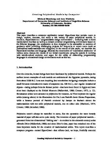
Figure 7. Compute latency bound for different configurations (comparing VIMD-IS, VIMD-US) [Measured for 1 ms of simulation execution] Comparing Effective Execution Time 3.5 VIMD-IS
VIMD-US
CNF2_LP
CNF3_LP
3 2.5 CET
VIMD
4
HLA OMT
1996
Number of Undetected Modeling Hierarchy Conflict
VIMD
2174
Number of Un-resolved Interaction
HLA OMT
VIMD
Struct. Partitio ning Funct. Partitio ning
HLA OMT
Number of interaction Described
Compute Latency Bound
2 1.5 1 0.5 0 CNF1_PP
CNF2_PP
CNF1_LP
PP_CNF_2
LP_CNF_1
LP_CNF_2
LP_CNF_3
Coverage
HLA/OMT Approach VIMD Approach
PP_CNF_1
Table 2. Success in HLA/OMT and VIMD approach
X
9
X
9
X
40%
9
9
9
9
9
100%
The results demonstrate that the VIMD approach can potentially increase sensitivity or correctness during multi-domain simulation. It can also offer more options of integration which will improve the design exploration time and eventually design quality. However, the VIMD approach does not lend itself to dynamism very well due to the fact that, model structure described in VIMD-information models are assumed to be static. In order to take advantage of the proposed VIMD method, adaptation layer development has to take place for different tools, thus restricting efficient tool-reuse. 8. COMPARING VIMD-IS AND VIMD-US View integration approach can be implemented using integrated simulation or as unified simulation. In this section we compare two implementations of the VIMD. For network simulation with increased number of interactions and shared states, the VIME-IS can be inefficient due to the communication and synchronization overhead. Additionally, VIMD-US offers inherently higher visibility which allows interaction management to be potentially more effective. For the sake of brevity we restrict comparison of the simulation speed for the above configurations.
Figure 8. Effective execution time for different configurations (comparing VIMD-IS, VIMD-US) [Measured for 1 ms of simulation execution] Speed of simulation execution will depend on the implementation scheme as well as the chosen unification configuration. Assuming that the system load and network congestions are same a comparison between VIMD-IS and VIMD-US can be made for all the configurations. Execution for a federate is measured as the amount of time the user process utilized the computer resources. Two computers connected via LAN are used for measuring the speed of execution. Each domain model or federate is executed on different machines. Execution time is measured using two approaches: Compute latency bound (CLB): This represents the minimum time the user would wait to finish the simulation – assuming maximum concurrency between all the domains. CLB = max{ET (i )} . Here ET(i) refers to execution time for domain i. Cumulative execution time (CET): This represents sum of all the execution overhead across all the domains. This means, CET = ∑ ET (i ) , here ET(i) refers to execution time for
0-7695-2622-5/06/$20.00 (c) 2006 IEEE
i =1.. N
domain i. This would be the case, if no concurrency between the domain models could not be achieved For VIMD-US, the above two measurements are same – since a single execution resource is assumed. More interesting observation is the CLB for both the approaches since it captures the efficiency of the model architecture. It can be seen that the VIMD-US offers to reduce the CLB between ~52% and ~58%. 9. CONCLUSIONS The paper describes a method of multi-domain modeling geared towards advanced communications and network system design. The method (VIMD) builds on the View Integration theory of data engineering. The details of the method and implementation approaches have been described. Based on TINA case-study, the paper demonstrates that the VIMD can improve the effectiveness of the multi-domain model unification significantly. View integration based approach can be implemented through integrated simulation (with an added middle-ware) or as a unified simulation (based on virtual prototyping approach). Comparing both the implementation approaches of VIMD, VIMD-US has been found more efficient compared to VIMD-IS. 10. REFERENCE [1]
[2]
[3]
[4]
[5]
[6] [7] [8]
[9]
[10]
[11]
[12]
[13]
HP, MIL3 First in the Industry to Integrate Network Management, Measurement and Planning, Press Release March 1998. http://www.opnet.com Bergstra, J.A. and P. Klint (1998). "The discrete time ToolBus -- software coordination architecture." Science of Computer Programming 31:205-229. Scacchi, W. and Mi, P. (1997) "Process Life Cycle "Engineering: A Knowledge-Based Approach and Environment". Intelligent Systems in Accounting, Finance, and Management, Vol. 6, pp. 83-107 Shashank Khanvilkar and Sol M. Shatz. “Tool integration for flexible simulation of distributed algorithms”, Software. Practice and. Experience. 2001; 31:1363–1380 (DOI: 10.1002/spe.419). Gabor Karsai, “Design Tool Integration: An exercise in semantic interoperability”, Proceedings of the IEEE Engineering of Computer Based Systems, Edinburg, UK, March, 2000. Richard M. Fujimoto, "Distributed Simulation Systems ", Proceedings of the 2003 Winter Simulation Conference "IEEE Standard for Modeling and Simulation (M&S) High Level Architecture (HLA) — Framework and Rules", IEEE Std 1516-2000 R. M. Fujimoto, K. Perumalla, A. Park, H. Wu, M. H. Ammar, G. F. Riley, “Large-Scale Network Simulation: How Big? How Fast?,” Symposium on Modeling, Analysis, and Simulation of Computer and Telecommunication Systems, 2000. "IEEE Standard for Modeling and Simulation (M&S) High Level Architecture (HLA)—Federate Interface Specification", IEEE Std 1516.12000 "IEEE Standard for Modeling and Simulation (M&S) High Level Architecture (HLA)—Object Model Template (OMT) Specification", IEEE Std 1516.2-2000 "IEEE Recommended Practice for High Level Architecture (HLA) Federation Development and Execution Process (FEDEP)", IEEE Std 1516.3™-2003 Stefano Spacapietra and Christine Parent, "View Integration : A Step Forward in Solving Structural Conflicts", IEEE Transactions on Knowledge and Data Engineering, Vol 6. No. 2, April 1994 Hienz Frank and Johann Eder, "Integration of Statecharts", Third International Conference of Cooperative Information Systems ,August 20 22, 1998 .
[14] Joachum Biskup and Bernhard Convent, "A Formal View Integration Method", Proceedings of the 1986 ACM SIGMOD international conference on Management of data [15] Markus Stumptner, Michael Schrefl, Georg Grossmann, "On the Road to Behavior-Based Integration", First Asia-Pacific Conference on Conceptual Modelling, APCCM2004, Dunedin, New Zealand. [16] Alexander Egyed and Nenad Medvidovic, "Extending Architectural Representation in UML with View Integration", Proceedings of the 2nd International Conference on the Unified Modeling Language (UML), Fort Collins, CO, October 1999, pp. 2-16 [17] C.Batini et. al. “A Comparative Analysis of Methodologies for database schema integration”, ACM Computing Surveys, Vol 15, No 4, pp. 323-364, Dec 1986. [18] M. H. Khan and V. K. Madisetti, “System Design and Re-Engineering Through Virtual Prototyping: A Temporal Model-Based Approach”, 1998 IEEE Asilomar Conf. on Signals, Systems, and Computers. [19] Lan-Rong Dung and Vijay K. Madisetti, 1996, Fall, “Conceptual Prototyping of Scalable Embedded DSP Systems,” IEEE Design and Test of Computers, pp. 54-65 [20] T. Egolf, M. et. al. 1996, November, "VHDL-Based Rapid System Prototyping," Journal of VLSI Signal Processing Systems for Signal, Image and Video Technology, pp. 125-56 [21] Thomas Magedanz, "Intelligent Network Evolution - Impact of Internet, CORBA, TINA and Mobile Agent Technologies", TINA 1999. [22] Bernard P. Ziegler and S. Mittal, “Modeling and Simulation of Ultra Large Networks: Methodology Responds to Challenges”, NSF Workshop on Modeling of Ultra-Large Networks, Nov 19-20,2001. [23] W. H. Sanders, “Multi-level and Multi-formalism Modeling of Ultra Large Networks”, NSF Workshop on Modeling of Ultra-Large Networks, Nov 1920,2001. [24] Moinul Khan and Vijay Madisetti, “Multidomain Modeling of Communications Networks Using View Integration”, 9th Communications and Networking Simulation Symposium, SpringSim2006, April 2-6,2006 . [25] Moinul Khan and Vijay Madisetti, “A Multidomain Modeling and Simulation for Advanced Services Design”, 1st International Conference on Communications System Software and Middleware, COMMSWARE, Jan 2-6 2006.
0-7695-2622-5/06/$20.00 (c) 2006 IEEE