The complete software is implemented on Matlab, but also a mobile phone ... working mosaicking application for a mobile phone, as will be shown in this paper.
Creating Panoramas on Mobile Phones Jani J. Boutelliera , Miguel Bordallo-Lopeza , Olli Silv´ena , Marius Ticob , Markku Vehvil¨ainenb a Machine
Vision Group, Dept. of Electrical and Information Engineering, P.O. Box 4500, FIN-90014, University of Oulu, Finland; b Nokia Research Center, P.O. Box 100, FIN-33721 Tampere, Finland ABSTRACT
Image stitching is used to combine several images into one wide-angled mosaic image. Traditionally mosaic images have been constructed from a few separate photographs, but nowadays that video recording has become commonplace even on mobile phones, it is possible to consider also video sequences as a source for mosaic images. However, most stitching methods require vast amounts of computational resources that make them unusable on mobile devices. We present a novel panorama stitching method that is designed to create high-quality image mosaics from both video clips and separate images even on low-resource devices. The software is able to create both 360 degree panoramas and perspective-corrected mosaics. Features of the software include among others: detection of moving objects, inter-frame color balancing and rotation correction. The application selects only the frames of highest quality for the final mosaic image. Low-quality frames are dropped on the fly while recording the frames for the mosaic. The complete software is implemented on Matlab, but also a mobile phone version exists. We present a complete solution from frame acquisition to panorama output with different resource profiles that suit various platforms. Keywords: mosaicking, panorama, stitching, mobile phone
1. INTRODUCTION Modern mobile phones have built-in digital cameras with increasing amounts of features, some models can even record video clips. Although mobile phone camera lenses tend to be wide-angled, there are some occasions where an even larger field of view is desired. In digital photography the answer to this need has been mosaicking for more than twenty years now. Some mobile phones already have elementary mosaicking capabilities, but advanced solutions to on-phone mosaicking are still missing. The biggest obstacles in creating serious mosaicking applications for mobile devices are the huge memory and computational resource requirements of mosaicking algorithms. Some high-end mosaicking methods1 calculate the result for more than one minute even on a modern desktop computer. However, with a carefully tailored algorithm it is nowadays possible to create a user-friendly and practically working mosaicking application for a mobile phone, as will be shown in this paper. We started to solve the problem by creating a reference algorithm for the Matlab-environment, keeping the resticted resources in mind all the time. Then, after several working alternatives had been tested in Matlab, a restricted-feature Symbian version was created. Both versions are designed to be used with a video recording device as input, but can also create mosaics from a few photos.
2. RELATED WORK Some commercial mosaicking applications for mobile phones have emerged lately. SonyEricsson has had a panorama shooting mode2 in their phones for a while now, although it is only capable of joining a few images. There are also a few Symbian-based3–5 applications, that provide panoramic imaging. Unfortunately there is only a restricted amount of public information available on these products. Therefore, we will look more into the related work that has been done in the domain of desktop computers.
Figure 1. Our algorithm crops frames immediately after capturing them. There is a lot of data redundancy between consecutive frames and thus cropping saves both memory space and computational resources in image registration. The cropped frame has roughly one third of the original frame’s width and 90% of its height.
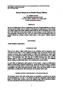
Figure 2. An example mask that is used to smoothly combine two frames when there is a moving object in either of the frames. The white area represent the displayed portion of one image and the black area the displayed portion of the second image. The gray area in between produces a combination of both images.
2.1. Mosaicking on Personal Computers There are many publications1, 6, 7 that cover complete mosaicking solutions, but we will now look into the solutions that are used in different phases of stitching to see how individual parts of mosaicing are implemented. The whole process of creating a mosaic image consists of several smaller tasks, of which image registration is the most important one. Stitching algorithms use both feature-based8 and direct approaches6, 7 in the registration process. The definitions and properties of these two fundamentally different methods are explained well in the survey of Zitov´ a and Flusser.9 An image stitching algorithm needs to use some kind of motion detection to avoid the distortion of moving objects.7 This problem and its solutions are covered extensively in the survey of Radke.10 In stitching applications, Davis7 solved the problem by drawing the seams around moving objects by Dijkstra’s algorithm. In the method created by Zhu6 the moving objects were extracted by differencing three successive frames and defined further by calculating an active contour for each object. Once the registration and motion detection is done, the images can be stitched. The stitching process consists of local blending operations and of radiometric adjustments. The paper of Zomet11 contains a good comparison of image blending methods and also proposes a new approach of optimizing the stitching result by a gradientbased cost function. Szeliski proposed a simple, local blending method to eliminate seam artifacts.12 Xiao13 reduced the exposure differences of an image pair by setting the mean and standard deviation of the registered image to be the same as that of the reference image. Traditionally mosaicking applications have used all given images for the mosaic that is to be created. In a previous paper14 we proposed a new method to select the most suitable frame from a group of neighboring frames. In addition to our work, this approach has not been addressed much. The work closest to ours has been made by Li.15 In the method of Li the amount of distortion caused by rotation and perspective is evaluated and a suitable subset of images is chosen to form a mosaic. Also Hsu8 has selected frames for the construction of a panorama. He has only considered the criteria of suitable overlap.
3. THE MATLAB VERSION OF OUR PROGRAM The Matlab version of our program takes a video file as input. It reads one frame at a time from the video file, as if capturing video from a camera. After a frame is acquired, it is immediately cropped (See Figure 1), transformed to gray-scale and registered against the previous frame by the method of Vandewalle.16 Motion detection is also performed and the frame’s blurredness is computed. The program keeps acquiring frames until it notices that the camera has moved a certain distance from its initial location (noticed from image registration results), after which the best frame is picked from the group
of suitable frames.14 Depending on the program’s configuration, the selected frame is stored to a mass storage device, or kept in the memory. This process is repeated until the video stream ends. After the frame acquisition has ended, a second registration process is started. This begins by setting the centermost frame of all frames as a root frame. A shortest spanning tree is then constructed between frames based on their mutual translations. Then each frame is re-registered against its parent, much like in Marzotto’s method.17 This ensures that the accumulated registration errors from the first phase disappear and that the registration is done over the shortest distances. In the final phase of the algorithm, some user input is requested (see Subsection 3.6) and the frames are stitched together to form a mosaic. In the beginning of the stitching process each frame’s brightness and contrast is adjusted so that the mean error between consecutive frames is minimized (see Subsection 3.7). The details of the stitching are explained in subsection 3.8.
3.1. Projection and Camera Motion Model We used the idea of manifold projection, originally introduced by Peleg.18 In manifold projection a thin strip is taken from the center of each frame to be used in the construction of the mosaic image. Peleg states that the frames can be registered accurately by a rigid camera motion model if it is assumed that significant motion parallax or change of scale does not occur. Manifold projection offers excellent image quality, since frames do not have to be projected to a different surface for the construction of the mosaic. Manifold projection is also quick to process.
3.2. Image Registration Our method relies on the recent image registration method of Vandewalle,16 that can register aliased, rotated and translated frames. Depending on the resource profile that is set, the registration method differs somewhat (see Table 1 for details). When the fixed 64x64 registration template is used, the registration method tends to produce some crudely wrong results. To cope with these errors, an error-correcting method is used: each time a frame is registered, its motion vector is compared to the motion vector of the previous frame. If the difference between the adjacent motion vectors surpasses a certain threshold, the motion vector is replaced by the previous motion vector. This works very well in panorama imaging, where the usual motion trajectory of the camera is close to linear. As was explained in the algorithm overview, registration is also done for a second time. The second registration uses the complete overlapping areas of the frames regardless of the resource profile. Generally there are such few frames in the second registration, that computing time will not become an issue. Thus, the registration template sizes are always arbitrary and rotation correction is always turned on. However, motion detection can not be done anymore since the frame overlaps are so small after the majority of captured frames have been discarded.
3.3. Blur Detection The amount of motion blur in the frame is computed as a side-product14 of Vandewalle’s method, or acquired by summed derivatives in profile level 0. The method of summed derivatives estimates the image’s sharpness by summing together the derivates of each row and each column (A similar method was used in a recent publication19 ). Both methods of blur calculation produce one single number that expresses the amount of high-frequency detail in the image. The value is only sensible if it is used to compare images: if a certain image Ia acquires a higher result than image Ib, it means that Ia has more high-frequency detail than image Ib (implying that both images depict approximately the same scene). Usually this means that Ia is sharper than image Ib, but in some occasions the difference in the image content distorts the result.
Figure 3. Effect of blur detection. The images are small pieces of a mosaic that was constructed from a video recorded by a shaking camera. The mosaic on the right has been constructed without blur detection.
Figure 4. Effect of motion detection. The image on the left is a part of a panorama created by our algorithm with motion detection enabled. The middle image is also from our algorithm, but motion detection is disabled. The image on the right is created by Autostitch.1
3.4. Motion Detection Motion detection is done in a very simple fashion to make the process fast. First, the difference between the current frame and the previous frame is computed. The result is a two-dimensional matrix that covers the overlapping area of the two frames. Then, this matrix is low-pass filtered to remove noise and is thresholded against a fixed value to produce a binary motion map. If the binary image contains a sufficient amount of pixels that are classified as motion, the dimensions of the assumed moving object are determined statistically. First, the centerpoint of the object is approximated by computing the average coordinates of all moving pixels. Second, the standard deviation of coordinates is used to approximate the dimensions of the object. Evidently this method produces the wrong result when there are multiple moving objects is the same frame. However, it has proven to be a good compromise between computational efficiency and robustness. Figure 4 shows the effect of motion detection.
3.5. Frame Selection The frame selection process is a matter of weighting the importance of different frame features. According to experiments, the presence of moving objects is the most important criteria, since the most severe artifacts are
Figure 5. Effect of barrel distortion correction.
created in the stitching process by moving objects that get clipped. The factor of second highest importance was chosen to be the amount of blur. This procedure is explained in more detail in our previous publication.14
3.6. Mosaic Type Handling During the frame registration the program constantly watches over the horizontal translation of the current frame compared to the first frame in the video clip. If a certain maximum translation is surpassed, the program assumes that the video clip depicts a 360 degree panorama and stops the frame acquisition. The threshold translation for this decision is affected by the field of view of the camera and needs to be determined explicitly for each imaging device that is used by this algorithm. When the image acquisition has ended, some user input is requested to produce a panorama that corresponds the user’s wishes. If the panorama is detected to be 360 degrees, the user is asked to point out the wished center point of the panorama. Since the panorama is recorded as an ordinary image file, the user may wish to put a certain detail to the center of the panorama. After the user has selected the centerpoint, the second-phase registration is performed around that point (see Subsection 3.2). If the panorama is less that 360 degrees, the user is asked to show two points in the image that lie on the (possibly hidden) horizon. When the program knows the location of the horizon, it can rotate the image so that the horizon is leveled and also correct the barrel distortion of the image. The parameters of barrel distortion correction depend on the used camera lens and must be determined manually. The used barrel distortion correction function is dn = d + kd3 . (1) Parameter k was empirically detected to be a function of the mosaic width in a linear fashion. The barrel distortion correction equation is very simplistic but is empirically detected to produce sufficiently good results (See Figures 5 and 8). However, the equation has only been tested with one type of camera lens and might produce bad results with certain types of lenses.
3.7. Exposure Correction Exposure correction is needed because most video recording devices automatically adjust the camera’s aperture and exposure time to keep the video frames from getting over- or underexposured. Exposure correction makes the video pleasant to watch on playback, but makes the creation of panoramas complicated. If the effect of exposure correction would be omitted while creating a panorama, there would be visible vertical stripes between the individual frames that compose the panorama. The effects of exposure correction can be corrected globally and locally. Local correction works on individual pixels and is usually referred as blending, which is described in the next subsection. On the contrary, global
correction adjusts the color values of whole frames. After trying out several methods, the best method was noticed to be the use of minimization of square errors. The method is as follows: // calculate mean and standard deviation for each color channel and frame for frame_index = 1:framecount for c = 1:channelcount m0(c,frame_index) = mean2(wholearea,c,frame); s0(c,frame_index) = std2(wholearea,c,frame); end end // calculate mean and standard deviation for each overlapping frame part for frame_index = 2:framecount prevframe = frame_index - 1; overlap = getoverlap(frame, prevframe); for c = 1:channelcount ca(c,frame_index-1) = mean2(overlap, c, prevframe) - m0(c,frame_index-1); cb(c,frame_index-1) = mean2(overlap, c, frame) - m0(c,frame_index); sa(c,frame_index-1) = std2(overlap, c, prevframe) - s0(c,frame_index-1); sb(c,frame_index-1) = std2(overlap, c, frame) - s0(c,frame_index); end end for c = 1:channelcount mc(c,:) = findminimum(m0(c,:),ca(c,:),cb(c,:),40); sc(c,:) = findminimum(s0(c,:),sa(c,:),sb(c,:),60); for frame_index = 1:framecount //set new means to frames frame(wholearea,c) = frame(wholearea,c) - m0(c,frame_index))*sc(c,frame_index)/s0(c,frame_index) + mc(c,frame_index); end end ================================================================== function result = findminimum(m0,ca,cb,weight) global NUM_FRAMES M0 CA CB WT M0 = m0; CA = ca; CB = cb; WT = weight; NUM_FRAMES = length(m0); m = M0; // initial estimate result = fminunc(@err_dist,m,optimset(’Display’,’off’)); ================================================================== function errorv = err_dist(m) global NUM_FRAMES M0 CA CB WT errorv = 0; // rule 1: keep difference from non-adjusted frames at minimum
for i = 1:NUM_FRAMES errorv = errorv + (m(i) - M0(i))^2; end // reduce the impact of rule 1 errorv = errorv / WT; // rule 2: make overlap area differences as small as possible for i = 2:NUM_FRAMES errorv = errorv + ((m(i-1) + CA(i-1)) - (m(i) + CB(i-1)))^2; end
3.8. Blending In our method blending is done with a gaussian weighting mask20 if no moving objects are present. If there are moving objects, the seam is drawn outside the boundaries of moving objects. A mask is created for the overlapping area of the images that are to be stitched. That mask is divided into two parts by the borders of the moving area that is present in either of the frames. The mask, that is practically a grayscale matrix, is then strongly low-pass filtered to create a smooth transition around the border area. The resulting mask (Figure 2) is a two-dimensional matrix with two areas divided by a smooth ramp. A combined image is computed by weighting the original frames with this mask.
3.9. Resource Profiles To suit various platforms, our program has been designed to work with various resource profiles that enable and disable computationally intensive tasks. There are three levels, from 0 to 2. Table 1 describes the effects of levels.
4. SYMBIAN VERSION OF OUR PROGRAM The Symbian version of the program uses a limited set of features when compared to the Matlab version. These limitations are because of the scarce computational resources and limited memory. A principal difference to the Matlab version is that frame selection and image registration are done after the video clip is captured. Although it happens off-line, the speed of registration is negligible.
4.1. Registration and Frame Selection Image registration is done also here with the method of Vandewalle. The registration uses a fixed square template of 128x128 pixels from each frame along with the error correction scheme described in subsection 3.2. A fixedpoint C code version provides a computation speed of three frames per second on Nokia N90. The performance could be improved further by an optimized assembly-code implementation. Rotation estimation is in progress, but its feasibility is not yet proven, since it might consume too much time on present mobile phones. Motion detection is not yet implemented. Blur detection is done with the simple method of summed derivatives and frame selection is done in a similar way as in the Matlab version. Some results can be seen in Figures 6 and 7.
Table 1. The effect of resource profiles to the features of the mosaicking application. Application speed is calculated as a relative value to the speed of profile 0. A speed of 50% would mean that the computations take twice as long as with level 0.
Profile
Registration
Motion Detection
Rotation Correction
Speed
0
64x64
no
no
100%
1
arb.
no
no
43%
2
arb.
yes
yes
30%
4.2. Blending The frame blending is done with a linear function that gradually merges one frame to the next by changing the frames’ weight. A similar method has been used in12 under the name feathering. User input is not yet used for mosaic post-processing.
5. EXPERIMENTAL RESULTS Our mosaicking program has been tested with a wide variety of videos and it has proven to be very robust thanks to the excellent registration method. The main strengths of our algorithm are speed, sharpness of results and motion detection. The 360 degree panorama displayed in Figure 6 consisting of 243 frames, was created in 65 seconds by the Matlab version of our program (profile 2). Autostitch (a C++ program) took 280 seconds for the same video clip on the same computer (3.4GHz PC). The sharpness of the results can best be seen in Figure 4. A careful comparison between the images created by Autostich and our method shows that our method creates clearly sharper results. This is caused by the blending method that does not average all available information to the result, but selects the data only from one image for each area (except the narrow seam areas). Another feature that affects the result sharpness is blur detection. Figure 3 depicts how frame choosing can affect the output in some situations. The effect of motion detection can also be seen from Figure 4. Naturally, panoramas are mostly created from places where there is not much movement in sight, but in some situations it might be impossible to create a panorama without a moving object getting into it. In these situations motion detection is helpful, since it tries to avoid cutting up the moving objects. Of course, there are many situations where simple motion detection cannot create a good result. This happens mostly when an object moves to the same direction as the camera pans. Also, if there are many moving objects in the video that are not wished to be shown, a more advanced scheme, like in Zhu’s6 method, should be applied. In many fields, our algorithm outperforms the state-of-the-art method Autostitch.1 However, there is one situation where Autostitch performs remarkably better. When a panorama video is recorded in an area that has large objects close to the camera, the perspective effects are so strong that our method cannot handle them properly, unlike Autostitch.
6. CONCLUSIONS We have presented a method to create good-quality panoramas that runs even on low-resource devices like mobile phones. Moreover, our method outperforms a state-of-the-art stiching method in many fields. The Symbian version of our algorithm is being improved constantly. Motion detection, rotation correction and overall speed optimizations are under construction.
REFERENCES 1. M. Brown and D. G. Lowe, “Recognising panoramas,” in ICCV ’03: Proceedings of the Ninth IEEE International Conference on Computer Vision, p. 1218, IEEE Computer Society, (Washington, DC, USA), 2003. 2. SonyEricsson, “K700i user manual.” PDF file, 2004. 3. http://panoman.net, “Bitside panoman.” Home Page, 2006. 4. http://www.scalado.com, “Scalado autorama.” Press Release, 2006. 5. http://www.emccsoft.co.uk/includes/uploads/File/Qinetiq1.pdf, “Emcc snapdv mobile.” Press Release, 2006. 6. Z. Zhu, G. Xu, E. Riseman, and A. Hanson, “Fast generation of dynamic and multi-resolution 360 degrees panorama from video sequences,” in Proceedings of the IEEE International Conference on Multimedia Computing and Systems, 1, pp. 400–406, (Florence, Italy), 1999. 7. J. Davis, “Mosaics of scenes with moving objects,” in CVPR ’98: Proceedings of the IEEE Computer Society Conference on Computer Vision and Pattern Recognition, pp. 354–360, IEEE Computer Society, (Washington, DC, USA), 1998.
8. C.-T. Hsu, T.-H. Cheng, R. A. Beuker, and J.-K. Horng, “Feature-based video mosaic,” in Proceedings of the International Conference on Image Processing, 2, pp. 887–890, (Vancouver, Canada), 2000. 9. B. Zitov´a and J. Flusser, “Image registration methods: a survey.,” Image and Vision Computing 21(11), pp. 977–1000, 2003. 10. R. J. Radke, S. Andra, O. Al-Kofahi, and B. Roysam, “Image change detection algorithms: a systematic survey.,” IEEE Transactions on Image Processing 14(3), pp. 294–307, 2005. 11. A. Zomet, A. Levin, S. Peleg, and Y. Weiss, “Seamless image stitching by minimizing false edges,” IEEE Transactions on Image Processing 15(4), pp. 969–977, 2006. 12. R. Szeliski, “Video mosaics for virtual environments,” IEEE Computer Graphics & Applications 16, pp. 22– 30, March 1996. 13. F. Xiao, H.-Z. Wu, L. Xiao, Y. Tang, and W.-J. Ma, “Auto method for ambient light independent panorama mosaics,” in Proceedings of International Conference on Machine Learning and Cybernetics, 6, pp. 3851– 3854, IEEE, (Shanghai, China), 2004. 14. J. Boutellier and O. Silven, “Panoramas from partially blurred video,” in IWICPAS06, pp. 300–307, 2006. 15. J. S. Li and S. Randhawa, “Improved video mosaic construction by selecting a suitable subset of video images,” in CRPIT ’04: Proceedings of the 27th conference on Australasian computer science, pp. 143–149, Australian Computer Society, Inc., (Darlinghurst, Australia), 2004. 16. P. Vandewalle, S. S¨ usstrunk, and M. Vetterli, “A Frequency Domain Approach to Registration of Aliased Images with Application to Super-Resolution,” EURASIP Journal on Applied Signal Processing (special issue on Super-resolution) 2006, pp. Article ID 71459, 14 pages, 2006. 17. R. Marzotto, A. Fusiello, and V. Murino, “High resolution video mosaicing with global alignment,” in Proceedings of the IEEE Computer Society Conference on Computer Vision and Pattern Recognition, 01, pp. 692–698, IEEE Computer Society, (Los Alamitos, CA, USA), 2004. 18. S. Peleg and J. Herman, “Panoramic mosaics by manifold projection,” in CVPR ’97: Proceedings of the 1997 Conference on Computer Vision and Pattern Recognition (CVPR ’97), pp. 338–343, IEEE Computer Society, (Washington, DC, USA), 1997. 19. J. Liang, D. DeMenthon, and D. Doermann, “Camera-based document image mosaicing,” in ICPR ’06: Proceedings of the 18th International Conference on Pattern Recognition (ICPR’06), pp. 476–479, IEEE Computer Society, (Washington, DC, USA), 2006. 20. M. Heikkil¨ a and M. Pietik¨ ainen, “An image mosaicing module for wide-area surveillance,” in VSSN ’05: Proceedings of the third ACM international workshop on Video surveillance & sensor networks, pp. 11–18, ACM Press, (New York, NY, USA), 2005.
Figure 6. Top: An example 360 degree panorama made from compressed video by the Figure 7. A vertical mosaic Matlab version of our program. The mosaic has been afterwards cut in two for better constructed on the Symbian viewing. Below: A panorama created by the Symbian version of our program. version of the program.
Figure 8. A barrel distortion -corrected panorama (Matlab Version).